The scooter switch pinout is a diagram of its connection to the scooter's electrical circuit. There are several types of devices: for example, in Chinese models a DC or AC type switch can be used. They differ from each other not only visually, but also in the principle of energy accumulation for further creation of a spark. DC takes energy directly from the battery, while AC is tied to the generator coil.
Scooter switch pinout
The scooter switch pinout is a diagram of its connection to the scooter's electrical circuit. There are several types of devices: for example, in Chinese models a DC or AC type switch can be used. They differ from each other not only visually, but also in the principle of energy accumulation for further creation of a spark. DC takes energy directly from the battery, while AC is tied to the generator coil.
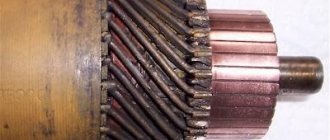
Generator
Owners of 50cc who are familiar with the design of the scooter will immediately understand the purpose of this device. It produces an alternating electric current that powers the moped when the engine is running. But the second main task is to charge the battery while working. That is, the battery ensures the operation of the devices when the engine is turned off, and then the generator takes on this task.
The connection is made according to the following principle. There are several wires coming from the generator. The negative tire is attached to the frame of the scooter. There is alternating voltage on the white wire, which is immediately sent for rectification and stabilization.
In the electrical circuit, the yellow wire powers the low and high beam lights. Additionally, a Hall sensor is located in the generator housing. Its task is to generate impulses to control sparking. It is not electrically connected to the generator; it is connected to a white-green and red-black wire. The sensor is connected to the CDI block.
Types of scooter switches
Before connecting the switch, it is important to know what type your scooter requires. If you connect the wrong device or do it incorrectly, the switch will immediately fail. The problem is that the part has the same plugs, but you can tell them apart. It's worth starting with the fact that DC is much larger in size.
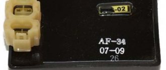
AC CDI is much more common. It is installed on most Chinese and some Japanese vehicle models. Most often, such a switch is found on those scooters that have a 139QMB or 157QMJ engine.
A slightly different AC switch is installed on “Alpha”, “Delta” mopeds, and other equipment with a 1P39FMB motor. Such a switch operates from a generator coil and requires alternating voltage
DC has a different type of power supply - from a battery, so it has
12V, and if you connect it to a generator, the switch will break. AC is more durable in this regard; most likely, it simply will not work until you connect it correctly.
Let's summarize the above
First, use a light bulb to check whether the switch generates a pulse or not:
- If the light is on, the switch and the modules that ensure its operation are 100% operational
- If the light does not light, it means that the switch or some module that ensures its operation has failed. And to understand for sure that the switch is faulty, we need to check all the modules.
- If the modules turn out to be serviceable, but the switch does not generate a pulse, then it is faulty and you can safely replace it with a new one
In conclusion, I would like to warn you against the temptation to take a known-good switch from someone and plug it in instead of your own. Yes, with this express method the faulty switch will be identified immediately. If it was really faulty, then with a known good one, a spark will immediately appear.
But how can we be 100% sure that the wiring of the scooter is in perfect order and no one has managed to put their smart personality into it before you?.. What if something shorted or some tusk messed up the wiring in his own way and then the working switch will receive a “complete butt”. And then you will buy two switches - one for the person you asked for, the second for yourself. Do you need it?
Pinout
If you have a 4T motor installed on your scooter, the pinout of the switch will depend on what type the scooter requires. For DC it will be as follows:
- The leftmost terminal on top should connect to the generator sensor.
- Ground is connected to the terminal located under it. You can tie the negative wire, for example, to the body of a moped; it is important that the part is metal.
- The upper terminal, located in the center, is connected to the wire leading to the ignition coil drive.
- The one located under it is also connected to the negative wire (ground).
- The wire from the ignition switch is connected to the upper rightmost terminal, which is needed to turn off the engine.
- The power wire is connected to the terminal located under it; it also comes from the ignition switch.
If you have an AC type, the location of the terminals is the same, but they are connected differently:
- We move from left to right, first the top row, then the bottom.
- Here the wire from the generator sensor goes, as in the previous version.
- Next comes the ignition coil wire.
- And at the end there is a “silencer” for the ignition switch.
- The first two terminals are the negative wire, “ground”.
- To the last remaining terminal we connect the power wire from the high-voltage winding of the generator. This point is the main difference when connecting an AC switch from a DC one.
Scooter Honda Dio AF 18 27
The Honda Dio AF 18 has a slightly different switch, made in Japan, which is why the pinout of the scooter is a little unique, and the mounts on the switch are different. It is connected as follows: from left to right, first the upper, then the lower terminals. Location:
- Hall Sensor.
- Ignition coil.
- Weight.
- Ignition lock.
- Power wire from a high voltage coil.
Yamaha Jog Scooter
Several types of generator can be installed on this type of motor vehicle. The most common option has 5 contacts, with wires already coming out of it. Therefore, if you have original wiring, you need to connect as follows:
- Orange should lead to the ignition coil and alternator.
- Black - to the ignition switch.
- Purple – Hall sensor.
- The remaining two wires are connected to the ignition coil.
Chinese scooters
Typically, such vehicles have standard switches, which were described above. The connection diagram depends on whether the AC or DC device is installed on your vehicle. It is worth remembering that different types of switches are not interchangeable.
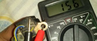
Checking the power supply of the AC CDI switch
We switch the tester to the alternating current measurement mode for the 200V range. We touch the ground with one probe, the power wire with the second and crank the engine with the starter:
- If the supply voltage is at least 60-65V, the power supply is normal.
- If the voltage is significantly less or absent, check the generator. The supply winding of the generator in the mode of cranking the engine with the starter should produce at least 60V, and at average engine speeds - about 160V
Electrics and electrical equipment of a scooter
Dedicated to all owners of Chinese scooters...
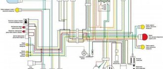
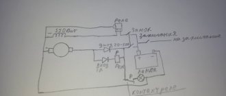
To begin with, I would like to present a wiring diagram for a Chinese scooter.
Since all Chinese scooters are very similar, like Siamese twins, their electrical circuits are practically no different.
The diagram was found on the Internet and is, in my opinion, one of the most successful, since it shows the color of the connecting conductors. This greatly simplifies the diagram and makes it more comfortable to read.
(Click on the image to enlarge. The image will open in a new window).
It is worth noting that in the electrical circuit of a scooter, just like in any electronic circuit, there is a common wire . On a scooter, the common wire is the minus ( - ). In the diagram, the common wire is shown in green . If you look more closely, you will notice that it is connected to all the electrical equipment of the scooter: headlight ( 16 ), turn relay ( 24 ), instrument panel backlight lamp ( 15 ), indicator lamps ( 20 , 36 , 22 , 17 ), tachometer ( 18 ), fuel level sensor ( 14 ), horn ( 31 ), tail light/brake light ( 13 ), start relay ( 10 ) and other devices.
First, let's go over the main elements of the Chinese scooter circuit.
Egnition lock.
Ignition switch ( 12 ) or “Main switch”. The ignition switch is nothing more than a regular multi-position switch. Even though the ignition switch has 3 positions, the electrical circuit uses only 2.
When the key is in the first position, the red and black wires are connected. In this case, the voltage from the battery enters the electric circuit of the scooter, the scooter is ready to start. The fuel level indicator, tachometer, sound signal, turn relay, and ignition circuit are also ready for operation. They are supplied with power from the battery.
Where is the switch located on the scooter? — Alisa-motors
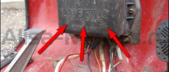
The switch is such a thing that is very afraid of moisture, and even more so of water getting on it. Therefore, scooter manufacturers try to install the switch somewhere under the plastic or under the seat. This aspiration is quite logical and justified.
Most "Chinese" models have the switch installed in the area of the engine compartment (as on most cars), on most - on the frame on the right side. To get to it, you need to remove the seat tank and inspect the frame to see if there is a small black box on it to which a plug with wires is connected - this will be the switch we are looking for (for those who don’t know)
For some scooter models, the switch may be located deep in the plastic, almost under the driver’s feet, for others - under the tank
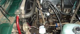
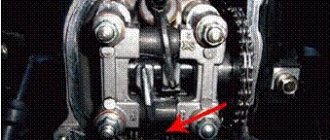
If you have some super-duper “Chinese” on which you just can’t find the device that every scooter rider needs so much, don’t despair, gather your willpower and try to turn on the logic: the switch works in close tandem with the generator - these are two completely dependent devices from each other. The generator has two windings that ensure the operation of the commutator. The wires of these windings are always connected directly to the commutator.
Your task: find the output of the generator wires from the engine and move along it to two connectors: a plug and two round terminals
After two wires with round terminals have been found, we move along these wires until we reach 100% of what we need
alisa-motors.ru
Ignition circuit elements.
One of the most important electrical circuits in a scooter is the ignition circuit. It includes the CDI ignition module ( 1 ), ignition coil ( 2 ), spark plug ( 3 ).
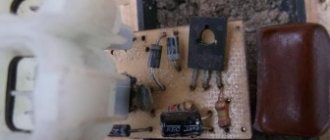
CDI ignition module.
The CDI ignition module ( 1 ) is made in the form of a small box filled with compound. This makes it difficult to disassemble the CDI unit if it malfunctions. Although the modular design of this unit simplifies the process of replacing it.
There are 5 wires connected to the CDI module. The CDI module itself is located in the bottom of the scooter body near the battery compartment and is secured to the frame with a rubber clamp. Access to the CDI block is made difficult by the fact that it is located in the bottom part and is covered with decorative plastic, which has to be completely removed.
Ignition coil.
Ignition coil ( 2 ). The ignition coil itself is located on the right side of the scooter and is mounted on the frame. It is a kind of plastic barrel with two connectors for connection and a high-voltage wire output that goes to the spark plug.
Structurally, the ignition coil is located next to the start relay. To protect against dust, dirt and accidental short circuits, the coil is covered with a rubber cover.
Spark plug.
A7TC spark plug ( 3 ).
The spark plug turned out to be cleverly hidden on the scooter, and it can take quite a long time to find it the first time. But if we “walk” along the high-voltage wire from the ignition coil, the wire will lead us straight to the spark plug cap.
The cap is removed from the candle with a little effort. It is fixed to the spark plug contact with an elastic metal latch.
It is worth noting that the high-voltage wire is connected to the cap without soldering. The insulated stranded wire is simply screwed onto the screw contact built into the cap. Therefore, you should not pull the wire too hard, otherwise you can pull the wire out of the cap. This can be easily fixed, but the wire will have to be shortened by 0.5 - 1 cm.
It's not so easy to get to the spark plug itself. To dismantle it, a socket wrench is required. With its help, the candle is simply unscrewed from its seat.
Starter ( 8 ). The starter is used to start the engine. It is located in the middle part of the scooter next to the engine. It's not easy to get to.
Why there is no spark on a 4t scooter: causes and solutions
The main reason why a scooter will not start is a malfunction of the ignition system. The main sign of such a malfunction is a weak spark on the scooter or its absence at all. In the article you will learn about possible ignition failures, diagnostics, and repair methods.
What does the ignition system consist of?
Such a system on a scooter includes the following devices:
- battery
- starter
- current generator
- switch
- coil
- lock
- candle
- wiring.
Although all these elements have different sizes, costs and complexity of the device, their importance in the proper operation of motorcycle equipment is almost equal. The malfunction of just one of the above elements leads to a malfunction of the entire scooter.
Each of these devices has its own possible malfunctions. Let's discuss each device in order in which repairs should be made.
Spark plug
The most common breakdown in the ignition system (including why there is no spark on a scooter) is a faulty spark plug. The reasons are completely different: carbon deposits due to poor fuel quality (or oil); overheat; lean or enriched air-fuel mixture and others.
The candle should be clean, without much carbon deposits, brick color
You can assess its condition visually by unscrewing it from the cylinder. The working color of the candle is brick. But white and black indicate problems in her work. The best way to solve the problem is to replace it with a new one. If this is not possible, then clean it with a brush, rags or heat it on a gas burner.
The spark test is carried out in the following order:
- The spark plug is unscrewed from the cylinder along with the tip.
- The spark plug body is leaned against a metal “mass”.
- The engine rotates with the crank or starter, and sparks should jump between the electrodes of the spark plug.
To check the spark plug, lean it against the metal body of the scooter.
Remember! If a spark appears during replacement, then the ignition system is in order and you should move on to diagnosing other parts of the scooter.
Ignition coil
If the spark plug is replaced with a new one, but the scooter (moped) still does not start, we diagnose the coil. The coil is a device with two windings - primary and secondary. Visually, it is a barrel with two contacts and a high-voltage wire coming out.
The role of the coil is to increase the incoming voltage hundreds of times. The primary winding has two contacts as outputs. The secondary winding is located between the positive contact and the end of the high-voltage wire. Violation of the integrity of one of the windings leads to failure of the main task and, as a result, the absence of a spark.
It is better to start diagnosing the coil with the spark plug cap. Inside the cap there is an interference suppression resistor, which also fails. You can check it with a multimeter in resistance measurement mode. You need to connect probes to the unscrewed cap - one to the spark plug seat, the other to the end for the armor wire. The resistance is considered normal - within 5 kOhm. If not correct, replace the cap.
DC CDI switch
One of the most famous switches due to the ease of connection. The most common one has only 4 contacts for the following wires:
Despite its simplicity, there are many switches of this type. It is available with and without a maximum speed limiter, with variable ignition timing, and with additional contacts for a wide variety of needs. In particular, you can “hook” a side stand to some switches, so that when opened, the engine will not spin up to the speed at which the clutch engages. This is done in order to insure the driver against dangerous rash actions.
Stock switch for scooter
A stock or original switch is the one that is installed on the vehicle from the factory. Its main advantage over others is that it is already designed for the equipment with which it operates; it is often equipped with a limiter so that the engine does not develop speeds that are dangerous to the life and life of the main bearings, the entire crank mechanism, cylinder-piston groups and other structures and assemblies. The stock commutator is the main source of a well thought out engine's longevity, efficiency and durability. Those who take the risk of replacing a factory switch with a sports (tuning) one are risking a lot. Those who do not fully understand what they intend to do risk even more. Inept installation of such parts and their subsequent use with a conventional engine often lead to a decrease in service life and the death of the engine, sometimes on the same day.
Connection diagram (pinout) of the scooter switch
This article will present connection diagrams (pinouts) for switches, the most popular scooter models in Russia. Also, whenever possible, switches will be opened in order to study their contents in detail.
We kindly ask readers who are well versed in electronics to express in the comments their assessment of the quality, design and tuning capabilities of the switches presented in this article.
Let's start with the switch model installed on Chinese scooters equipped with a 139QMB engine. Such a switch is of the DC-CDI type, and is quite rare in the “Chinese”.
This switch is of the AC CDI type and is installed on the vast majority of “Chinese” vehicles equipped with 139QMB, 157QMJ engines.
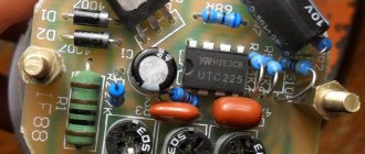
This switch after opening.
This switch is of the AC CDI type and is installed on Chinese mopeds “Alpha” and “Delta” equipped with a 1P39FMB engine.
“Silencer” - a wire that goes into the ignition switch connector or into the alarm connector; when the ignition is turned off, the wire shorts to ground and the scooter stalls.
The sensor is a wire coming from the magnetic induction sensor of the generator.
160V - the switch is powered by alternating voltage directly from the generator coil (drive).
12V — the switch is powered by constant voltage directly from the battery.
Checking the generator sensor
The magnetic induction sensor is a key element of the ignition system. And if there is any suspicion of a problem with the ignition system, it should also be checked.
Switch the tester to AC measurement mode in the 2V range. With one probe we touch the ground, with the second probe we touch the white-blue or red-yellow wire coming from the sensor and turn the engine with the starter.
- If numbers flash on the screen, there is an impulse
- If the display shows zeros, check the sensor
There is momentum
How to connect a switch on a scooter
09 May 2012, 22:21
thyristor - any 600 volt, more is possible)): 1-t1 2-t2 3-G resistors: p1- 200-220ohm (you can play with the limiter, this one is responsible for maximum speed) p2- 5kOhm p3- 2.5kOhm capacitors: c1 - 50v 10mf (pole) s2 - 22nf s3 - 1mf 400-600 volts any silicon diodes: 1N4001 (for example)
the cost of production does not exceed 100 rubles. I personally assembled 5 such devices, they work right away and do not require any configuration.
PS if anyone needs to disassemble a flooded block, please contact me, I’ll disassemble it and draw a diagram
09 May 2012, 23:06
Here's the diagram you have.
but such schemes (in different variations) are more expensive on mopeds.
They have an ignition timing system (if you’re interested, I’ll tell you in more detail) if you put your circuit instead, it won’t really drive.
And there are DC-CDI units with 12 volt power supply in the same cases and with the same connectors.
Re: Chinese switch circuit diagram
09 May 2012, 23:57
Re: Chinese switch circuit diagram
10 May 2012, 00:05
Re: Chinese switch circuit diagram
10 May 2012, 00:37
Re: Chinese switch circuit diagram
10 May 2012, 00:54
Just don’t copy it, it’s worth a penny. If you want to design it, take the car ignition as a basis. radio magazine 12.2002 page 33
Re: Chinese switch circuit diagram
10 May 2012, 17:03
Re: Chinese switch circuit diagram
10 May 2012, 17:33
Re: Chinese switch circuit diagram
10 May 2012, 17:59
Re: Chinese switch circuit diagram
10 May 2012, 20:39
Re: Chinese switch circuit diagram
10 May 2012, 22:09
Re: Chinese switch circuit diagram
10 May 2012, 22:12
To each his own. &-92&-63о-о3-47 It’s not love that saves, but sex and rock and roll! (c) GZ
repair of foreign-made motor vehicles, welding, turning, drinking works.
Re: Chinese switch circuit diagram
10 May 2012, 22:31
Re: Chinese switch circuit diagram
10 May 2012, 23:31
Re: Chinese switch circuit diagram
11 May 2012, 07:25
Re: Chinese switch circuit diagram
11 May 2012, 09:09
Re: Chinese switch circuit diagram
11 May 2012, 10:31
And I took a programmer from the chipodipo. I received it the other day, checked it yesterday. AVR-ISP500. Otherwise, the old one no longer uses ATmega & ATtiny via LPT. Yes, and you can’t connect it to a laptop-book. Now I’ll finish one thing for the NS, and then I want to install a CDI on it with a DC converter and a variable SPD. Naturally on a microcontroller. Yes, and for CB1 there is a mosk with Atmel already installed, I want to experiment.
And the simplest commutator for a scooter had to be assembled almost in the field using twisted cables. And it didn’t go away, it worked. Not ideal, but it started up, our thyristor was 2U202N, its control was stupid, like three for. off to the heap!
Re: Chinese switch circuit diagram
11 May 2012, 10:54
Re: Chinese switch circuit diagram
12 Jun 2021, 22:02
It works primitively: a transistor is used to start and idle, it opens with a negative impulse from the sensor. upon reaching operating speed (
2200 is adjusted by a variable resistor), the sensor voltage begins to open the thyristor with a positive pulse. The difference from complex circuits is step switching.
Re: Chinese switch circuit diagram
13 Jun 2021, 16:46