Unlike similar Soviet-era motorcycle models, the electrical wiring diagram of the IZH Jupiter 5 motorcycle provides for operation from a battery with air-cooled equipment. This causes many problems for owners. The article provides recommendations for modernization that solves problems with sparking.
Ignition Connection Diagram Izh Jupiter 5
Thanks to the electronic device, adjusting the unit will not take much time and effort.
In this case, do not unscrew or remove the modulator, otherwise you will have to install everything again! Set the ignition separately for each cylinder.
After this, the screws must be tightened tightly. How to connect Chinese wiring Izh Planet Izh Jupiter
Then loosen the screw and turn the eccentric. For reference: unlike the Jupiter model, new wiring and an electronic ignition system were installed on the modified IZ Planet 5. If it was not possible to cause a spark using the steps described above, then the reason for the incorrect operation is incorrect connections.
Keep in mind that you will also have to adjust the outline at the same time. Do not try to fix the wire with your hands - it will jump so hard that sparks will fly out of your eyes.
Burnt contacts, oily spark plugs and batteries with a charge of less than 12 V further worsen sparking. It is very important that the modulator plate passes through the slots of the sensor itself.
It should fit into the hole made in the sensor. In the diagram above, the numbers indicate: Spark plugs;.
We do wiring on IZ Jupiter 5
Switching elements.
These include switches (high-low, turns, engine stop, etc.) as well as brake and neutral sensors and the ignition switch. You can easily “ring” them with a tester, finding out which contact group is not working.
Switching also includes the Izh electronic turn signal relay. Its malfunction is visible by the absence of interruption or no voltage supply to the turn signals.
As can be seen from all of the above, the wiring on Izh Planet is without any special secrets or complex elements, all its parts are easily diagnosed and repairs should not cause difficulties.
Now we advise you to watch the video, which shows in detail and clearly the assembly of the Izh Planet 5 circuit.
Checking the serviceability of the generator can be done on a motorcycle without disassembling the generator.
To carry out the work you will need a multimeter.
1. Place the motorcycle on the center stand or side stand.
2. Disconnect the battery by removing its fuse.
3. Remove the right cover of the power unit.
unscrew the nuts securing the five “upper” wires of the generator. In order not to confuse the wires during subsequent assembly, we mark them or tie them with thin wire so that we get a cable.
Comments and reviews
This will not be enough to fully accumulate the energy resource in the coil. In what cases is ignition adjustment necessary?
The voltage at pin 3 is formed by a measuring circuit consisting of a phototransistor and resistor R4, which equivalently constitute the same divider.
During the operation of the vehicle, the owner faces many problems. Scooters and mopeds Electrical circuit of IZH Jupiter 5 Unlike many Soviet-era motorcycles, the electrical wiring diagram of IZH Jupiter 5 was created for battery use with water-cooled equipment.
It is advisable to use a pin, since many are not able to perform all the necessary actions in total; A set of wires with connectors for ignition without contact from VAZ. Of the entire mass, only a common plus is required.
It is better to take a coil for 1-cylinder devices
In other cases, you should pay attention to previously grounded candles.
The ignition timing must match on any cylinder used. Motorcycle wiring IZH Planet 5
Features of electrical equipment
Models of IZH motorcycles are as unified as possible. The wiring diagram for IZ Jupiter 2 is not much different from later versions of the IZ motorcycle. There are external differences. For example, the Planet 5 bike has one cylinder, and the Jupiter 5 has two.
The first 12-volt motorcycle was the IZH Jupiter 4. The wiring diagram for the IZH Jupiter 5 and the wiring diagram for the IZH Jupiter 3 differ in components.
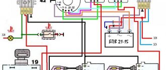
Wiring diagram IZ Jupiter 5
The bike of the fifth Jupiter has a contact SZ, which is powered by a battery, so the operation of the vehicle is highly dependent on the state of charge of the battery.
If charging is insufficient, the following problems occur:
- the motor runs intermittently;
- the engine starts with difficulty;
- At low speed the battery is discharged.
These problems can be eliminated by switching to BSZ. Any electrician can handle this task (the author of the video is Viter Electronic).
How to make the transition to contactless SZ?
To switch to contactless SZ, motorcyclists use parts from other motorcycle models. When upgrading the generator set, the wiring of the IZH Jupiter 5 remains unchanged. Minor alterations concern the electrical circuit of the IZH. After changes, the battery is used to service auxiliary equipment. To switch to BSZ, parts are taken from Planet 5 and the VAZ 2108 car.
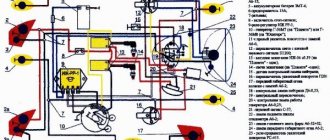
The following changes are being made to the electrical circuit of IZH:
- install 2 Hall sensors from the eighth VAZ model;
- 2 VAZ electronic switches must be connected to the sensors;
- each of the cylinders serves a commutator-sensor pair;
- You need to add two more ignition coils to the circuit.
SZ after modernization
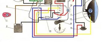
On the electrical circuit of the IZH motorcycle, the components are marked with numbers:
- Spark plug.
- Ignition coils from Planet 5.
- Switches.
- Hall sensors.
- Egnition lock.
- Battery.
For the created ignition system, it is necessary to modify the IZ Jupiter 5 generator, the circuit of which will not require major changes.
How can I modify the generator?
The presented modernization option is advantageous in that it does not require the purchase of a new generator that will service the new ignition system.
Recycled generator design
All you need to do is follow these steps:
- make a modulator-breaker of an electrical circuit;
- install a breaker on the rotor shaft or generator.
You can create a modulator with your own hands. To do this, you need to take a metal plate and drill a hole in it for the fastening bolt. The manufactured part will serve as a modulator-chopper.
Homemade modulator for interruption
The modulator is connected as follows:
- install the modulator plate (2) and tighten it with the bolt (3), but not all the way;
- by rotating the crankshaft, you need to ensure that the piston is at top dead center;
- Next you need to set the ignition timing;
- Now you can tighten the mounting bolt on the plate.
Hall sensors (1) are installed together with the modulator.
Izh Jupiter 5 ignition switch connection diagram
We mark the Hall sensor mount in such a way that the distance to the rear wall of the sensor through the magnet slot from the center of the armature is around mm.
What advantages open up to users who decide to install electronic ignition on the Izh Jupiter are described below. Get a nightmare! Thanks to the modulator plate, smooth ignition operation is ensured.
What kind of precise engine operation can we talk about here? An ignition adjustment is necessary if the engine is running poorly, the muffler or carburetor is firing. As soon as the voltage is on the pin.
A caliper will be needed as a depth gauge. The most common of them are listed below: Ignition gaps change their original position while driving a few days after adjustment; A spark occurs every once in a while, since the contacts regularly burn out; Capacitors are constantly damaged; Low spark power; If you add two or three volts to the battery, it is quite difficult to start it. If the engine is 1-cylinder, then the cutout angle in the modulator should be approximately degrees, but if the engine is 2-cylinder, then the cutout angles should be 60 degrees.
Its thickness is 0.45 mm. We connect the second wire from the switch to terminal “1” of the ignition switch; the second wire from the same terminal goes to the signal. Tighten the screws well.
Replacing the head light Riding Jupiter 5 at night is the lot of the most daring and experienced bikers. Thus, the coils are supplied with 12 volt voltage from the battery (diagram 1). The ignition timing must match on any cylinder used. If your spark appears earlier or later, then perform the following steps. We determine the moment of spark by the spark itself.
Connect it to the second and third contacts of the DC. After turning on this key position, power is supplied from the battery to the primary circuit according to a simplified scheme. Now you can use BSZ. Then loosen the screw and turn the eccentric. As a result, a charge of less than 12 V appears on the spark plug, which poorly ignites the combustible mixture in the cylinders.
A discharge is applied to the spark plug, which causes the mixture to ignite, causing the crankshaft to start moving. Using the generator bolt, turn the crankshaft clockwise. It is necessary to ensure that the breaker contacts open to the maximum distance. The characteristic knocking sounds of iron components in the crankcase and accompanying detonations also disappeared. WIRING TO IZH (PLANET 5)
Improving the standard system
The ignition system can be improved in other ways. To do this, you need to identify what problems there are with the wiring. They can occur in the primary circuit between the coil and the 12V battery or due to operating conditions. A visual inspection of the primary circuit can reveal problems with connections, contacts and the ignition switch.
If operating conditions are ideal, the primary circuit will operate with a 12V battery without failure.
But when dirt and dust get into the circuit, the resistance at the contact points increases, which entails a decrease in voltage from 12 Volts to 7-8 Volts. This voltage is not enough for a powerful discharge to appear in the secondary winding of the coil. As a result, a charge of less than 12 V appears on the spark plug, which poorly ignites the combustible mixture in the cylinders. Burnt contacts, oily spark plugs and batteries with a charge of less than 12 V further worsen sparking.
Standard wiring after modification
The following measures help solve these problems:
- The plug connectors are removed and each wire is soldered using traditional soldering and then insulated.
- An additional toggle switch is installed that turns off all consumers when the engine starts. Thus, the coils are supplied with 12 volt voltage from the battery (diagram 1).
- Remake the ignition switch (IZ) (diagram 2). You need to take a wire and solder one end of it to the connector of lock 4, which is free, and the other to the positive terminal of the coil. The standard wire should be re-soldered from terminal 5 to terminal 6. After turning on this position of the key, power is supplied from the battery to the primary circuit according to a simplified scheme.
Thus, the changes made will make the electrical wiring of the IZH Jupiter 5 motorcycle more reliable and efficient.
Installation of BSZ on Izh Jupiter-5: advantages of the system
The level of current consumed by the node in this case will be no more than 2.
It is very important that the modulator plate passes through the slots of the sensor itself. An ignition adjustment is necessary if the engine is running poorly, the muffler or carburetor is firing.
Now it remains to supply a spark at the right time to the cylinders, for this: We make a plate for attaching the Hall sensor. Some believe that the diodes shine a little brighter, which means your actions will be noticeable to other road users.
When the hall sensor can be secured, we apply the modulator. Pay more attention to its location in relation to the sensor. Of the entire mass, only a common plus is required.
A spark should appear on the spark plugs. When setting up a BSZ on Izh Jupiter-5 BSZ, it is necessary to take into account a number of nuances that can significantly affect the operation of the equipment used. A guide to action, so to speak. At this moment a spark is formed.
The tension will be quite enough. The most serious failure is related to the engine. The switch, coil and hall sensor are connected by wiring.
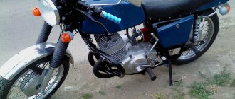
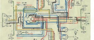
Izh Jupiter 5 motorcycle diagram
Next, insert the bolt into the hole, clamp the workpiece with a nut on the back side and insert it into the drill chuck. Replacing a device or adjusting it at home is not so difficult, but you need to remember that incorrect actions can lead to possible malfunctions in the future. Unstable sparking is often caused by an incorrect design of the so-called magnetic flux contactor. If your spark appears earlier or later, then perform the following steps. It happens that the flywheel bolt, which connects the two halves of the crankshaft, comes loose, begins to play and does not work well.
After some km, the spread of ignition timing due to crankshaft chatter will be about 4 mm from the set value. The contact ignition is not able to work normally if the bearings are damaged. Wiring from scratch. Izh Jupiter/planet 4.5
Detailed wiring diagram for IZ Jupiter 5 - problems and their solutions
There is no need to have special stands and equipment for repairs. A minimum knowledge of electrical engineering and a simple avometer (tester) is enough; even often you can get by with just a test lamp.
We will tell you in more detail about the main electrical wiring components and possible malfunctions. The Izh Planet wiring diagram makes it easy to find a broken wire or damaged insulation (for example, a bad contact always gets hot).
But pay special attention to the fact that the electrical circuit is designed not only for 12 volts, there is also a high-voltage cable (connecting the coil and the spark plug), which cannot be checked with a regular ohmmeter.
In this case, we look to see if there is a spark at the coil output and at the output at the spark plug contact. Let's take a closer look at the main wiring components of the Izh Planet.
services and repairs
The power source on both IZh 5 and 6 motorcycles is a battery and a 3-phase alternating current generator. The algorithm of actions is as follows: Make the adjustment with the low beam on in accordance with the screen markings in Fig.
When the clearance is correctly set, the engine idles stably. It’s quite easy to check it yourself, the test scheme is as follows: Disconnect the battery, then remove the generator cover. The switch is housed in a hermetically sealed plastic case, which prevents moisture from entering. The problem with Planet 5 motorcycles is the lack of a separate fuse box, and often in the event of a malfunction it is necessary to inspect the entire electrical wiring. On both IZH 5 and 6 bikes there may be problems with the sound signal; it may sound weaker. During operation it does not require maintenance and cannot be repaired. Some owners remove the battery themselves or remove the main fuse if the electrical circuit is damaged and there is no time or desire to deal with it. Spark plug tip for IZH 7 motorcycles.
You can also download for free and via a direct link an archive with circuit diagrams. Then you should check the resistance between the stator terminals by touching them one by one with probes. But the IZ wiring diagram is unlikely to be useful for conversion - practically nothing from the namesake car fits the motorcycle. Simple wiring for a motorcycle part 2
Differences from the second Planet
For many modern citizens, the information that domestic motorcycle manufacturers worked tirelessly to improve their models in an era of total shortages may come as a surprise.
Note! The fact takes place, moreover, it is supported by official documents, in particular 1970N04P16-17 - this is the outgoing number of the factory newsletter, which described the changes made.
In the photo - official materials of the Izhmash Design Bureau
The new generation motorcycle received:
- Direction indicator lights are a first in domestic practice;
- Semiconductor relay for controlling direction indicators (installed in the headlight);
- New size of wheels and tires (3.50x18 versus previous - 3.25x19);
- New brand increased capacity battery (old one on IZH Planet 2 - ZMT-6);
- And, of course, more engine power. The power unit now developed 18 hp.
Modifications
But the creator engineers did not stop there and, having released the five-millionth car from the production line, presented a modification of the IZH Planet 3-01.
Mirror and safety arches are the distinctive features of the new modification
Among the innovations it should be noted:
- Rear passenger footrests;
- Roll bars;
- Rearview mirror;
- New steering wheel design.
For reference: The buyer paid for the changes out of his own pocket. In particular, the price for IZH Planet 3-01 was 750 rubles, the version with a stroller was 1140, and the “rural version” was even more expensive. Fortunately, care instructions were included with purchase, which made maintenance easier.
IZH Planet 3-01 with wide wheels of smaller diameter - “rural version”
Wiring Problems
Practice shows that if the motorcycle was stored in a dry garage and was not subjected to dubious alterations, then the Jupiter 5 wiring diagram lasts a very long time. From time to time you need to change some consumables, such as lamps and ignition coils, but otherwise it functions quite stably. However, this is not always the case and problems do occur, for example:
- wire breaks;
- electrical circuit short-circuit;
- failure of their individual branches of the circuit;
- weak light from incandescent lamps;
- incorrect operation of indicators;
- misfire;
- reduction in engine power;
- complete failure of the system.
The problems described above can arise both due to natural wear and tear of wiring elements, and after incompetent intervention in the circuit. There is no universal solution to the problem in this case, and in order to find out what caused the breakdown, you should be patient and have some basic knowledge of the technical part of the motorcycle. First of all, you should get a multimeter or assemble a primitive network indicator using a 12-volt light bulb to “ring” the wiring for breaks. Having found a circuit node that is not working correctly or a wiring break, it will need to be eliminated, the network’s functionality re-checked, and so on, until operation is completely restored.
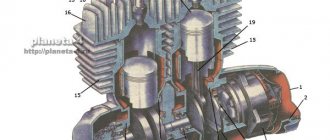
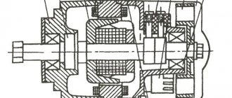
Generator rotor 281.3701
The generator rotor 1 is located inside the stator. It is installed on the crankshaft using bolt 3 and key 5. An excitation winding 6 is wound on the rotor core with a copper wire with a diameter of 0.56 mm, 600 turns are made. The winding resistance is approximately 6.4 ohms. For contact with the winding, two copper rings 2 and carbon brushes are used. They perform the work of a current collector.
How to remove the generator rotor 281.3701
The breaker cam 4 is installed in one position on the rotor shaft in a special socket and secured with a mounting bolt 3. Under this cam there is a thread that is intended for removing the rotor from the crankshaft. To remove the rotor, you need to screw the screw from the chain disassembly device into the thread. The device is located in the motorcycle tool. If there is no screw, you can use a regular bolt with an M10 thread. The only condition for the thread must be at least 70 mm. Turn until the screw rests on the crankshaft. Then we apply more force to tighten it, and the rotor is removed from the shaft.
Electrical equipment IZH Planet 5
Wiring for IZH Planet 5 includes:
Video: review of IZH Planet 5 wiring
Taken by user Agronom.
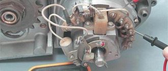
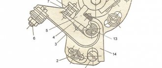
Generator
IZ Planet 5 generator design:
- voltage regulator with rectifier BPV-14-10 - 1;
- rotor - 2;
- stator with windings - 3;
- current collector brushes - 4;
- ignition system cam (battery) - 5;
- ignition system contact unit - 6.
The generator converts the mechanical energy of a gasoline engine into electrical energy, which charges the battery. Alternating current is generated by 3 windings and fed to a rectifier, which converts it into direct current. An additional coil is used as an exciter.
Photo gallery: IZH Planet 5 generator and its design
Generator IZH Planet 5 Generator design
Battery
To supply all components, a low-power energy storage device of 12 volts is required, since IZH Planet 5 does not have a starter. The purpose of a lead-acid battery is only to supply voltage to the ignition system and the excitation winding of the generator during startup.
Battery
Ignition system
In IZH Planet 5, the ignition coil converts low-voltage voltage into high-voltage and transmits it to the spark plug. That, in turn, is responsible for the spark that detonates the fuel. To ensure that detonation occurs only in the desired piston position, there is an ignition chopper.
How does the BPV 14-10 block, used on Izh motorcycles, work? how to repair it?
The appearance of the block is shown in Fig. 34, diagram - in Fig. 35. The technical data of the device are as follows: maximum direct current - 20 A, adjustable voltage at direct current from 2 to 10 A, supply frequency 165.800 Hz (1650.8000 rpm) and temperature 25±5°C - 13, 4. 14.3 V.
Rice. 34. Appearance of the BPV 14-10 block
The block consists of a power rectifier assembled on diodes V10-V15, connected to the phase windings of the generator (G) through contacts X4, X5, X7; a controlled rectifier using thyristors V5 and V7, diodes V6, V8, V9 and resistors R9 and R11, connected to the generator excitation winding circuit through contact X1.
Rice. 35. Block diagram BPV 14-10
The power rectifier is connected to the motorcycle load Rн and battery B via ignition switch B and contacts + X8 and -X2. The control lamp H is connected via -X2 and X3. Transistors V16 and V17, zener diode V2, diode V3 and resistors R3-R8 form a thyristor control circuit. Capacitor C1, diode V1 and resistors R1 and R2 make up the filter circuit. Diode V4 is designed to reduce the influence of the self-induction EMF of the excitation winding.
If there is any doubt about the operation of the unit, you should first check whether the electrical contact is broken at the points of connection of the circuits. The test should be carried out using this method.
With the ignition switch in position 1, the engine not running and the unit turned off, make sure that the generator phases and field windings are not shorted to the housing. To do this, connect a lamp of type A12-3 between the wire suitable for the +X8 terminal of the block, and alternately to the wires connected to the block terminals X4, X5, X7, - X1. The lamp should not be lit.
To make sure that the generator is working properly, turn off the unit and short-circuit the two wires in the mating connector going to -X1 and -X2. When the engine is idling, the lamp * should burn with a constant glow (voltage about 8 V). If the picture is different, the generator or the wires suitable to it are faulty. If at this stage the check shows that the generator and wires are in order, then the unit is to blame for the malfunction. The factory recommendation sets out the sequence of checking and repairing it as follows.
* (The lamp must be connected between phases C1-C2, C1-C3, C2-C3. Anyone who does not know the structure and principle of operation of a synchronous alternating current generator connects the lamp as when checking for a short to ground, but this is not correct. Note. Bulba Alexander.)
If the indicator lamp H does not light up when the ignition is on and the engine is not running, then:
you need to temporarily close the contacts -X1 with X3. If the lamp is working but does not light, the excitation circuit of the generator winding is faulty (winding breakage, brushes hanging, etc.). The lamp is on - turn off the ignition and continue checking;
temporarily close the control electrode of thyristor V5 with the connection point of diodes V1 and resistors R1 and R2, turn on the lock. If the lamp does not light, check the serviceability of resistor R1. If capacitor C1 is working, replace thyristor V5. The lamp is on - turn off the ignition switch and continue checking;
temporarily close the collector with the emitter of transistor V17, turn on the ignition switch. If the lamp does not light, replace the V6 diode with a working resistor R8. The lamp is on - turn off the ignition, continue checking;
temporarily disconnect the collector of transistor V16 from resistors R6, R5 and turn on the ignition switch. If the lamp does not light when resistors R5, R6, R7 and diode V3 are working, replace transistor V17. The lamp is on - turn off the lock, continue testing by connecting V16;
temporarily close the base with the emitter of transistor V16, turn on the ignition switch. If the lamp does not light, replace transistor V16. The lamp is on - replace the zener diode V2 with good resistors R3 and R4.
Keep in mind: after replacing zener diode V2 or transistor V16, it is necessary to check the regulated voltage at terminals + X8 and - X2 of the unit with the engine running at medium speed. Its value should be in the range from 13.5 to 14.2 V at an ambient temperature of 25±5°C. If the voltage is lower, increase R3 or decrease R2; if higher, reduce R3 or increase R2.
If the lamps burn out, the battery is recharged due to an increase in voltage (more than 14.2 V at 1650.8000 rpm and the temperature already indicated), then:
Connect a voltmeter to the +X8 and -X2 terminals of the block and short-circuit the control electrode of thyristor V5 to the -X2 terminal for the duration of the voltage measurement. If the voltage has not decreased to the battery voltage (12 V), replace thyristor V5 with working diodes V4, V8, V9. After replacement, repeat this check and, if the voltage does not decrease to 12 V, replace thyristor V7. The voltage has dropped - proceed to the next stage of testing;
How to improve the standard electrical system?
As we have already said, standard wiring does not cause any particular complaints due to its solidity, ability to withstand oxides and rust at the joints, without losing functionality. That is why complete replacement of wiring is a questionable procedure, but upgrading individual parts makes sense. By individual parts, we mean such functional elements as head lights, indicators, turn and stop lamps, ignition system, generator. Let's talk about each of the elements separately.
Switch P-200
Light switch with horn button (located on the left side of the steering wheel). To switch the low and high beam circuit, a P-200 type switch is used with a built-in push-button horn switch for three operating positions: neutral - the headlight lamp is off; far right – low beam is on; far left – high beam is on.
The horn button has a movable contact connected to ground and a fixed contact connected to one of the wires coming from the horn terminal. When you press the button, the contacts close and the signal circuit is completed.
Converting the electrical circuit to work without a battery
Unlike cars that have a closed engine and electrical wiring, parts of the IZH Planet 3 motorcycle are more susceptible to external factors than others:
- Rain and snow;
- Direct sunlight;
- Mechanical damage from bushes.
The factory instructions provide:
- The need to constantly check the electrolyte level in banks, because when the motorcycle tilts, it inevitably leaks out;
- The need to constantly check the electrolyte density. This forces motorcycle owners to have a hydrometer, distilled water and hydrochloric acid on hand to restore the required density with their own hands.
Installation of BSZ
Contactless ignition system - this element has become so popular that it rightfully occupies the place of the most popular improvement to the standard ignition circuit. From the factory, the IZ Jupiter 5 wiring model is equipped with a contact ignition system. It is unable to hold the ignition angle advance settings for a long time, has failures in operation and low accuracy. The disadvantages of this system can be listed for a very long time, so owners switch to electronic ignition, thereby increasing power, reducing consumption and getting a flat torque and power curve.
Maintenance
The owner can independently perform some maintenance procedures:
- check the motorcycle generator if the battery loses charge;
- set the gap between the breaker contacts;
- adjust the quality of the sound signal.
The need to inspect and adjust the wiring arises if:
- the motorcycle moves in the rain for a long time, as this causes oxidation of the contacts;
- a motorcyclist rides in an area with a lot of vegetation that damages wiring;
- The driver rides in snow in winter, which can stick to electrical wiring parts and damage them.
Self-check of the Planet 5 motorcycle generator in case of loss of charge
The cause of loss of charge in the IZH Planet 5 battery is most often a breakdown of the generator.
To check it yourself you need:
- multimeter device;
- straight screwdriver.
Step-by-step instruction
The following steps must be followed:
- Disconnect the wires from the battery and remove the generator cover.
- Disconnect the top 5 wires from the generator, first unscrewing their fastenings. In order not to mix up the wires during assembly, it is worth marking them.
- Measure the winding resistance using a multimeter in ohmmeter mode. To do this, you need to touch the body with one probe, and the other should be connected in turn to the 3 wires of the winding. There should be no short circuits, as indicated by the inscription on the multimeter screen.
- Test the resistance between the stator contacts: you need to touch them one by one with the multimeter probes. The value on the screen should be 8 ohms.
The presence of a short circuit in the 3rd stage or a discrepancy in the indicators in the 4th will indicate problems with the generator.
Causes and possible consequences of the malfunction
The generator may not work for the following reasons:
- malfunction of the voltage regulator (“pills”, “chocolates” in the slang of car enthusiasts);
- wear (destruction) of brushes;
- short circuit of the exciting winding (rotor);
- breakdown of diodes (located in the horseshoe);
- wear of bearings and bushings.
A faulty voltage regulator usually results in a lack of battery charge. In this case, the “battery” indicator light appears on the dashboard. The engine continues to run until the battery is discharged to approximately 8 - 9 volts.
During daylight hours, the battery charge may be enough for 30-50 kilometers, provided that the battery was well charged at the time the malfunction occurred.
If the output stages of the voltage regulator breakdown, a malfunction may occur due to an increase in the generator output voltage to 17 - 20 Volts. This recharges the battery. The consequence of overcharging is the process of boiling of the electrolyte. If signs of corrosion appear under the hood in the battery area, it is necessary to check the generator.
A breakdown of the diode bridge can occur when the battery is accidentally reversed (installing the terminals in the wrong polarity). Typically, diodes are punched in pairs in one arm. A faulty diode has a resistance close to zero. In this case, the stator winding of the generator operates in short circuit mode and becomes very hot.
After a few minutes of engine operation, the windings overheat, and a smell of burnt electrical wiring appears under the hood of the car. To avoid fire, the engine must be turned off and the generator checked.
Wear of the brushes leads to gradual failure of the generator. First, while driving, the charge indicator light on the dashboard begins to blink, then it begins to glow constantly. In many generator models, the brushes are changed together with the voltage regulator.