Terminals
- The letter “B” indicates the battery connection terminal
- The letter "P" indicates the starter relay terminal
- The letter "C" indicates the starter terminal
- The letter “Ш” indicates the terminal of the shunt winding
- The letter "YaSH" designates the terminal of the shunt and armature winding
Connection
- To terminal “B” we connect a thick red wire coming from the battery and a red thin wire with a fuse coming from the ignition switch (terminal AM)
- To the “P” terminal we connect a thin orange wire coming from the ignition switch (CT terminal)
- To terminal “C” we connect the thick red wire coming from the dyno starter.
To terminal “W” we connect the thin black one coming from the dyno starter
To the “YaSH” terminal we connect a thick black wire with a fuse coming from the dyno starter, a thin black wire coming from the dyno starter and a blue wire going to the generator charge control lamp
Wiring diagram of Ant moto equipment
Hai! This wiring diagram of the Ant equipment will be useful to those who restore old Soviet scooters. On our website All about motorcycles, such biker mechanics will find many useful images, as well as texts with tips on tuning iron horses, etc.
This resource also provides news from the world of biker sporting events.
The famous domestic scooter has become a rarity these days. Only occasionally is he encountered on the endless roads of his great homeland. You can buy it for relatively little money. On this motorcycle site you can study the technical characteristics of this utility vehicle.
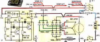
Explanations for the Ant Moto wiring diagram:
1) Direction indicators with bulbs.2) Battery (battery).3) Scooter speedometer.4) Speedometer dial backlight bulb.5) Motorcycle ignition system spark plug.6) Ignition system coil.7) Ignition system capacitor.8) Switching mechanism/ turning off the high beam and the sound signal. 9) Front parking light bulb. 10) Main lighting bulb (low/high beam). 11) Turn signal switch. 12) Sound signal playback device. 13) Scooter turn signal relay. 14) Switch. 15) Night light switch. 16) Generator operation identification indicator light. 17) Neutral transmission identification indicator indicator. 18) Identification mechanism for engaging neutral gear in the gearbox.19) Motorcycle clutch.20) Bike dynastarter.21) Interrupter for the ignition system of a Soviet scooter.22) Ignition system lock.23) Ignition system fuse.24) Stop switch/switch signal.25) Moto Ant relay-regulator.26) Switch block.27) Brake light bulb.28) Rear marker light.
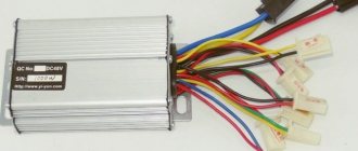
How to connect a relay regulator for an Ant scooter?
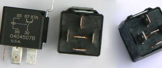
Connecting this idiotic device to many is no more difficult than plugging in a vacuum cleaner, and maybe even easier. It all depends on the desire and level of technical literacy of the owner of the Ant. On the cover of the relay regulator there are letters indicating the terminals.
- How to completely turn off the alarm without a key fob so that the car engine starts
- The letter “B” indicates the battery connection terminal
- The letter "P" indicates the starter relay terminal
- The letter "C" indicates the starter terminal
- The letter “Ш” indicates the terminal of the shunt winding
- The letter "YaSH" designates the terminal of the shunt and armature winding
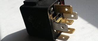
Why do you need a charging relay and how to check it
The charging relay is responsible for stabilizing the voltage in the scooter. Its malfunction can create serious problems for the vehicle owner. The first sign of a breakdown is the burnout of the light - the lamps receive increased voltage instead of the usual 12 V. Subsequently, the battery fails. And even if you change the relay after this, the changes that have occurred in the battery are irreversible, and its service life will be significantly reduced.
The voltage regulator is checked using a multimeter. It is connected to different parts of the circuit and the current indicators are studied. Basic moments:
- at idle speed the value on the stabilizer should be less than 15 V;
- on lighting fixtures the standard voltage is 12 V;
- the same value is typical for the general network of the scooter without load.
Pay attention to the type of current (direct or alternating) when taking measurements with a multimeter - correctly switch the operating modes of the device to be sure of the accuracy of the data obtained. If the battery contacts are not charged, you will have to change the relay regulator. You can do this yourself. The main thing is to use high-quality spare parts for the Ant scooter.
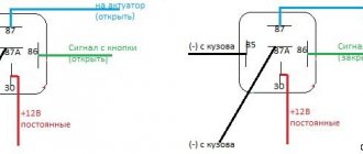
How to connect a dynastarter to a relay regulator?
Connecting the dynastarter to the relay regulator is not easy, but very simple. Didn't you know? And what exactly is there to connect? Some measly four wires. To some ancient relay. Well, okay, today I won’t rant too much, it’s better to get straight to the point.
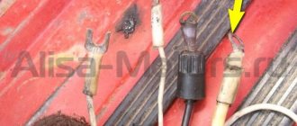
Four wires come out of the dynastarter stator, which are directly connected to the relay-regulator in a certain order: the first (clockwise, if the dynastarter stator is placed with the brushes down) wire (thin) goes to the “YaSh” terminal, the second wire (thin) goes to the terminal “Ш”, the third wire (thick) goes through the fuse to the “YaSh” terminal, the fourth wire (the thickest) goes to the “C” terminal.
Dynastarter wiring harness suitable for relay regulator. A thin wire with a plug at the end is connected to the “Sh” terminal, a thin wire with a regular terminal at the end is connected to the “YaSh” terminal, a thick wire with a fuse is also connected to the “YaSh” terminal, the thickest wire is connected to the “C” terminal of the relay regulator
And here we have a relay-regulator in person to which all this junk is connected.
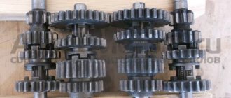
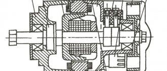
Design
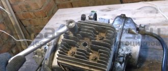
Rice. 2. Placing blocks in a scooter.
The ignition coil is protected from overheating at low speeds by a composite additional resistor SE-107, which is partially blocked by the “Start” button when starting the engine. The ignition coil should be installed closer to the spark plug. The author placed all the rest of the modernization in a special box attached to the side of the scooter (Fig. 2).
Connecting this idiotic device to many is no more difficult than plugging in a vacuum cleaner, and maybe even easier. It all depends on the desire and level of technical literacy of the owner of the Ant. On the cover of the relay regulator there are letters indicating the terminals.
Electrical circuit of the motor scooter Ant TG 200
The Ant TG 200 is based on its passenger car predecessor, the Tula T-200. The wiring diagram does not have complex components and is suitable for analogues of the Ant TG 200 scooter: TG-200F, TG-200I, TGA 200, TGA 200-01.
Download the electrical diagram of the Ant TG 200 scooter:
- Direction indicators
- Scooter battery
- Speedometer
- Speedometer backlight
- Spark plug
- Ignition coil
- Capacitor
- High beam and horn buttons
- Front side lights
- Low and high beam headlight
- Turn signal switch
- Sound signal
- Turn signal relay
- Switch
- Side light switch
- Battery charging indicator
- Neutral indicator
- Neutral sensor
- Clutch
- Scooter engine starter
- Breaker
- Egnition lock
- Fuse
- Brake light switch
- Relay regulator
- Switch block
- Brake light
- Tail light
Where is the best place to buy spare parts for the Ant scooter?
Many Russian supplying companies sell parts and components for motorcycles. Some of them are in direct contact with manufacturers and offer really decent spare parts for the Ant scooter. When choosing a supplier, take into account its reputation, product range, and professionalism of its employees. Not all companies operate throughout the country, preferring to serve only close clients. And, for example, the MotoImport online store provides delivery of spare parts to any region of Russia. And their selection of parts for the Ant scooter is quite wide.
Electrical circuit of the motor scooter Ant 2M
The electrical wiring of the Ant 2 and 2M scooter (prototype – Tulitsa 2) is located at the bottom of the scooter. The cargo-passenger version is slightly different in appearance and electrical equipment. A more detailed power supply diagram of Ant 2M allows you to repair and tune the electrical equipment of the scooter.
Download the electrical diagram of the Ant 2M scooter:
- Direction indicators
- headlight
- Indicator light (red) for dynastarter operation in generator mode
- Indicator lamp (green) for neutral activation
- Indicator lamp (orange) for direction indicator operation
- Indicator lamp (blue) for turning on the high beam headlights and the speedometer scale illumination lamp
- Sound signal
- Light breaker relay
- Side light switch
- Ignition switch and handbrake brake switch
- Switch for high/low beam and direction indicators
- Relay regulator
- Dynastarter
- Day/night switch with emergency engine shutdown
- Breaker
- Circuit breakers
- Capacitor
- Ignition coil
- Spark plug
- Neutral warning lamp switch
- Rechargeable batteries ZMTR-10
- Foot Brake Light Switch
- Rear light with brake light
Schematic diagram
As for the Ant's ignition system, you can upgrade it yourself. You can reduce the current passing through the contacts of the breaker using a transistor switch TK-102 (Fig. 1), which was used on the most common trucks in the past, ZIL-130, GAZ-53A, etc.
By reducing the current in this way by 6-8 times (to 0.3...0.8 A), we will make the breaker contacts almost eternal. The disadvantages of this solution include increased requirements for the cleanliness of contacts, since oil, dirt and dust caught between the contacts no longer burn out, as was the case with a conventional ignition system.
Rice. 1. Connection diagram of the transistor switch TK-102.
The use of a transistor switch makes it possible to use a higher-voltage B-114 ignition coil, which has a large secondary winding (41,500 turns). Since the voltage on the spark plug will increase from 17 to 25.30 kV, you can use a spark plug with a gap of up to 1.2 mm, which will save about 30% on gasoline.
Ignition on the ant
Go to page
captain 1st rank
Re: ignition on ant
Thank you. but I’ve already read everything. I even found information on some website about how to check the windings, I called, everything seemed fine, but I was confused by one thing. it seems that if you measure between the YAS terminal and the thick black wire there should be no more than 30 ohms, I have 15. is this critical or not?
captain 1st rank
Re: ignition on ant