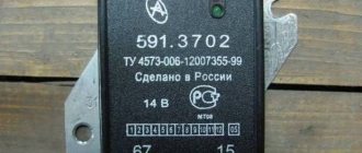
Connection diagram (pinout) of the scooter switch
This article will present connection diagrams (pinouts) for switches, the most popular scooter models in Russia.
Also, whenever possible, switches will be opened in order to study their contents in detail. We kindly ask readers who are well versed in electronics to express in the comments their assessment of the quality, design and tuning capabilities of the switches presented in this article.
Let's start with the switch model installed on Chinese scooters equipped with a 139QMB engine. Such a switch is of the DC-CDI type, and is quite rare in the “Chinese”.
This switch is of the AC CDI type and is installed on the vast majority of “Chinese” vehicles equipped with 139QMB, 157QMJ engines.
This switch after opening.
This switch is of the AC CDI type and is installed on Chinese mopeds “Alpha” and “Delta” equipped with a 1P39FMB engine.
“Silencer” - a wire that goes into the ignition switch connector or into the alarm connector; when the ignition is turned off, the wire shorts to ground and the scooter stalls.
The sensor is a wire coming from the magnetic induction sensor of the generator.
160V - the switch is powered by alternating voltage directly from the generator coil (drive).
12V — the switch is powered by constant voltage directly from the battery.
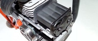
Qmb 139 generator power
There is no difference in engine operation (spark), they work the same. They differ in power for lighting (11 coils are more powerful, 8 are weaker), presumably 200 and 140 watts in the description of the scooter it is written exactly like that, which I myself doubt while watching the video about these generators on YouTube, because of this I wrote how many coils to make claims against I didn't care about this. When buying these generators, it is not written anywhere how many watts, I didn’t measure it myself, because the lighting power is different at different speeds, my stand spins 1500 rpm, maybe someday I’ll do a test, but I don’t have time yet, I myself use 8- mi and 11, it feels like 11 is more powerful
I DO NOT GIVE a guarantee on three-phase relays, because from the same batch there are some that do not hold voltage at all; three-phase relays come with an 11-coil generator. Buy 8-reel and there will be no problems
My advice, for those who want good and stable lighting, is to buy an 11-coil Generator and use a battery with it, because During the third season of sales and operation, I noticed that not all relay regulators “hold” the voltage and the light bulbs burn out, but as soon as you add a battery to the system, the voltage becomes stable at 13.5-14.5 volts.
The battery will only be needed for a stable voltage; if it is discharged or is missing, the engine will also start without the battery
Forget what was written above, the lamps are burning out, you are tired of these shitty relays, if you bought an 11-coil ignition and the bulbs are burning out, congratulations to you, you got exactly the same shitty relays, I am not responsible for them and I DO NOT GIVE A WARRANTY ON THE RELAYS, CONCLUSION, TAKE IT FOR YOU 8 OR 11 REEL
Source
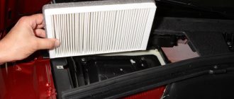
Photo report: Adjusting valves on a Chinese scooter (139QMB, 157QMJ)
During operation of a four-stroke air-cooled engine (such engines are found on most Chinese scooters and motorcycles), the cylinder head (hereinafter referred to as the cylinder head) can heat up to 260 degrees. This is, of course, not the operating temperature, but this is often the peak temperature.
The valves that are located directly in the cylinder head itself heat up in the same way as the head, with the only difference that the intake valve heats up a little less since it is cooled by the working mixture, and it is ordinary atmospheric air saturated with gasoline vapors, and the exhaust valve heats up much more. Since a flow of exhaust gases passes through the exhaust valve, the temperature can reach 600 degrees.
The problem is that metal parts expand when heated. Valves are no exception: during operation, the valve heats up and becomes a little longer. And when the valve becomes longer, it simply rests against the gas distribution mechanism and opens a little, or rather does not close completely (squeezed), due to which gases under high pressure seeping through leaks melt the working edges of the valve and its seats.
The edges of burnt valves look something like this.
By the way, not only the valves burn out, but also the sockets in which they sit
And this is what the working edges of valves and seats look like after repair.
As you can see, there is little point in regulating something that has already gone bankrupt for a long time. A burnt-out valve will no longer hold compression. And if you find that one of the valves has been jammed, then feel free to remove the head and grind the valves, otherwise there will be no point.
Gaps
Here is the combustion chamber of an ordinary Chinese scooter engine.
During engine operation, the valves heat up to significant levels. And in order to compensate for the expansion coefficient of the valve and the entire timing belt as a whole, there is a small gap between the valve and its opening mechanism. Called thermal.
In our case, the gap that we will adjust is between the valve and the rocker arm adjusting bolt. By tightening the adjusting bolt within the required limits, we can adjust the thermal gap as much as we need.
But do not forget that the gap should not be very large - otherwise the mechanism will work with a shock load and quickly fail. And very small: the valve will heat up, hit the rocker arm and burn out.
Preparation
From the above, you probably realized that the thermal gap exists in order to compensate for the thermal expansion of timing parts. The most important rule follows from this: the thermal gap can only be adjusted on a cold engine. If you start adjusting the heat when it’s hot, you’ll simply increase it since the initial gap will go to expansion. And when the engine cools down, the gap adjusted in this way will double. I hope this is clear.
Design and principle of operation of a scooter generator
To the average person who is not experienced in electrical matters, a scooter generator may seem like a very complicated device. This is partly true: electric current is an invisible thing to the eye, and if we can see or touch mechanical faults, then we can only guess about faults in the electrics of a scooter or identify them using special measuring devices.
However, “it’s not the Gods who burn the pots” and if a person has a desire for something, then this article will be a good help, but for those who don’t want anything, there’s no point in continuing.
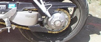
The scooter generator is a flywheel type generator with permanent magnet excitation. This type of generator is used on the vast majority of scooters, as well as mopeds and small motorcycles.
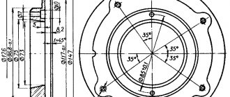
Designation of the main elements of the generator
The scooter generator consists of a rotor (in collective farm language - “anchor”) and a stator. The rotor is mounted directly on the crankshaft and while the engine is running, the rotor rotates around the stator coils
The stator is attached directly to the engine crankcase. And while the engine is running it remains motionless. The stator is a metal base made of several plates of special transformer iron. On the base of the stator there are special projections (coils) on top of which a copper wire is wound in a strictly defined order - forming the generator windings.
Depending on the generator model, there may be two or three windings. The generator shown below has three windings: supply, control and high-voltage
Permanent magnets are installed on the inner surface of the rotor. Magnets have different polarities. The magnets in the drain are covered with a lid; if you remove it, you can see them
Each magnet forms a static (constant) magnetic field around itself. In turn, the field of each magnet will be different: blue is negative (“north”), red is positive (“south”)
If we insert the stator into the rotor in the same way as is done on the engine, then we will see that the stator coils will be in the magnetic field of the magnets located next to them
After we start the engine, the rotor magnets will begin to rotate around the stator coils. During the rotation of the rotor, magnets of different polarities will approach the coils, which always stand still, and the field in which the coils are located will change at a very high speed. Due to the rapid change of magnetic fields, magnetic induction will occur in the generator coils and the generator will begin to generate electric current.
Current is good. But the current of a generator with excitation from permanent magnets is not a constant value and directly depends on the engine speed: the higher the engine speed, the more often the field of the coils changes - the induction increases and, as a result, the voltage in the coils increases. So it turns out that at idle engine speed the generator voltage will be 8-10V, and at maximum 60-70V.
In order to stabilize the generator voltage to specified limits, a special generator voltage regulating module was introduced into the scooter’s power supply system. That’s what it’s called: generator relay regulator
The principle of operation of the relay regulator is very simple: there are three windings on the generator stator: supply, high-voltage and control. The power winding is the main one and is designed to power the lights, sound signal and charge the battery.
The control winding is auxiliary and if the voltage in the supply winding increases, the relay-regulator supplies voltage to the control winding - the induction is disrupted and, as a result, the voltage in the supply winding of the generator drops.
When the voltage decreases, the opposite happens: the relay-regulator stops supplying current to the control winding, induction is restored, and the voltage in the supply winding increases.
The control and auxiliary windings of the generator are wound on the same coils
The high voltage winding is wound on individual coils or coil. The high-voltage coil is needed to form a spark on the spark plug and is only partially related to the generator. Rather, it relates to the ignition system, and this is a separate module and has little to do with the operation of the generator
Another auxiliary module of the generator is a load resistor. It is needed to ensure that the generator does not operate without load. For devices that generate current, working without a load is like death. The designers foresaw this possibility in advance and, in order to prevent the generator from running idle, they slightly loaded the supply winding onto the resistor
In addition to the elements described above, the scooter’s energy supply system includes an ignition sensor, which, at the right moment, ensures the formation of a spark at the spark plug.
This module is the same generator only in miniature and it works exactly on the same principle
On the outside of the rotor there is a small magnet in the form of a rectangular protrusion. This magnet, just like its larger brothers, forms a constant magnetic field around itself, and what happens next, you probably already guessed: while the engine is running, the field passes through the sensor coil and a small current is generated in it, which goes directly to the switch, controlling the torque in it sparking
Wednesday, April 4, 2012
Reworking the 139QMB engine generator.
Let's get back to our plan. The first item we have programmed is to re-solder the generator, so let's get to it. To get to the stator, you need to remove the rotor. To do this, remove its casing (it has an air intake), unscrew the 4 bolts on the impeller, we see this picture:
Unscrew the nut with a 15mm head (in the previous photo it is already unscrewed). To do this you will have to fix the rotor. I screwed the puller onto one bolt, rested it on the crankcase and unscrewed the nut. You can go the other way - fix the stationary cheek of the variator, but I strongly do not recommend it - if you use too much force, you can break the crankshaft. So, we unscrewed the nut. Now the hardest part is to rip the rotor off the key. A puller is required for this. For me it looks like this (as they say, for lack of a better one. I’ve been looking for a puller for a long time from Steve, who recommended above, they will carry out the operation of removing the rotor faster and more reliably):
Breaking the rotor was not an easy task. I already bent my puller, but still, with the last forces of tension, a shot occurred and it flew off the key. We unscrew the puller and remove the rotor from the stator coils:
And here is our stator itself:
We unscrew it and the induction sensor:
How should we proceed with altering the stator? Let's delve into the theory. There are several ways. You can only use the power winding, which is not the best option. It is more profitable to use the regulating one as well, this will increase the voltage by xx. It is also possible to rewind the entire stator except for the high voltage coils.
On the stator we unsolder this wire from the coil:
The gray wire is ours. For convenience, I disassembled the chip and brought out the wires along with ours, however, you can do it differently, for example, implant your wire into a free cell in the chip:
To activate the control winding, we will need to do the following:
That's it, the work with the stator is finished, we put it in place in the engine. Do not confuse which side you place the stator and the induction sensor: the stator is soldered towards itself, the high-voltage coils are on top, the sensor is in a round shape and the sensor itself is facing down. We put the rotor in place. Be careful not to let anything get into its magnets! We put the rotor exactly on the key. Tap it lightly in a circle and tighten with a nut. We put the impeller and casings in place. Congratulations, we have completed the first part of the work.
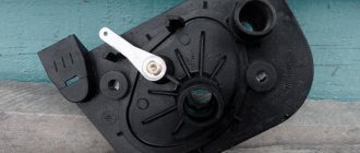
Replacing the voltage regulator. We have a low-power voltage regulator installed, which is both a rectifier and a stabilizer. Single-phase, half-wave. With it we have very little output power, which sometimes is not enough even to charge the battery normally. We need to turn it off. On different scooters it is installed in different places, but mainly in the beak. It looks like this: