Ural Generator Connection Diagram
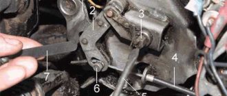
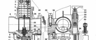
Generator circuit G 1 - cover; 2 — oil seal; 3 - rotor; 4 - stator winding; 5 - terminal block; 6 — back cover; 7 — shield assembly; 8 - rectifier block; 9 - fan; 10 — protective casing; 11 - bearing. Each brake mechanism has two hydraulic cylinders housed in one housing.
Generates alternating current.
Generator G is a three-phase synchronous AC electrical machine with electromagnetic excitation. motorcycle URAL generator 500w how to hook up If the belt bends more or less than specified, adjust the tension.
Preparing dry-charged batteries for operation The procedure for preparing batteries to bring them into working condition: remove the protective casing and cover, clean the batteries from dust, and the terminal bolts from grease; Unscrew the plugs from the filler holes, remove the sealing gaskets and clean the ventilation holes in the plugs.
During this period, you can slightly increase the generator voltage. The procedure for disassembling the generator: unscrew the two screws securing the brush holder and remove the brush holder; unscrew the coupling bolts and remove the cover from the side of the slip rings along with the stator; unscrew the nuts securing the phase leads from the rectifier block and separate the stator from the cover; Unscrew the pulley mounting nut and remove the pulley, fan, and support sleeve.
URAL engine diagram Ural cars are equipped with various options of diesel engines with power up to hp. The Urals are used both in geological exploration and by enterprises with difficult operating conditions for equipment, as well as by the armed forces of the Russian Federation.
This allows you to visually monitor the operation of the generator.
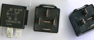
Relay regulator from VAZ for Dnepr Ural motorcycles
Restoration, testing, connection of the G424 generator
This is the kind of generator you want to see on a motorcycle.
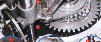
And this is what the generator of a Ural or Dnepr motorcycle usually looks like when it has been in operation.
- Let's get started. We disassemble the generator, clean the covers, degrease and prime. With this process everything is clear and does not cause any difficulties.
After the generator is disassembled, you can check the condition of the bearings, oil seal, and brushes. It's better to change it right away. Remove the bearings either with a puller or carefully cut them with a grinder.
Check: Winding on the rotor (armature). Winding on the stator. Checking for breakdown, ground, interturn short circuit and open circuit can be carried out by “continuity” using a multimeter. You can also check the diode bridge with a multimeter. More on this later.
Theory of generator operation and performance testing.
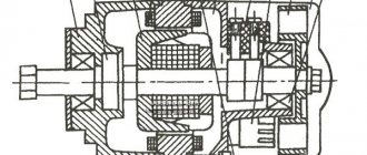
The figure below shows a diagram of the generator assembled (on the left) and on the right, disassembled into three parts.
Diode bridge, Stator winding (non-moving part) connected according to a star circuit and Armature (aka rotor, what rotates), brushes are just feed contacts.
Troubleshooting or testing should be divided into three parts: checking the stator winding, checking the armature winding, checking the bridge.
But first we should remind you how it all works.
Operating principle of three-phase alternator:
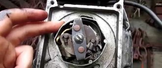
1. Excitation voltage is applied to the rotor winding using graphite brushes through contact rings.
2. Rotating inside the stator winding, the rotor winding through which current flows induces an EMF in the stator winding. Faraday's law. There are 3 stator windings and they are out of phase by 120 degrees.
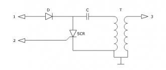
3. The alternating voltage is removed from the stator windings and converted to constant voltage by a diode bridge. In the diagram and graph below it is clear how alternating current is rectified into direct current by diodes.
In a three-phase alternating current generator, there is no permanent magnet; instead, there is an electromagnet in the form of one winding on the armature, which, when voltage is applied to it, “excites” generation.
This is what the assembled generator looks like with a circuit diagram superimposed on it.
Below is a diagram of connecting the generator to the on-board network with a relay regulator of a new three-pin model and an old one.
The difference in the above diagrams is in the relay regulator. In the circuit with the VAZ regulator, it is not necessary to connect the generator control terminal. The regulator itself has status diagnostic indicators.
The generator in the on-board network of a motorcycle is controlled in the same way as in a car.
A modern relay regulator is built on semiconductor elements and there is no relay in it as such; instead, an electronic key is organized, which is either open or closed. Also, the regulator relay contains a measuring element that is capable of measuring the generator output voltage and checking it with its reference voltage. At the moment when Uout. — the voltage at the generator output will be greater than Uop. - voltage support, RR will remove power from the excitation winding and generation will stop.
The engine is started and the rotor rotates in the stator winding, voltage is supplied to the excitation winding through the PP and the generator is excited. As long as the voltage supplied by the generator and the PP regulator is not high, it monitors that power is supplied to the excitation winding.
By increasing the engine speed, the voltage on the generator will increase, since the dependence of the voltage on the generator speed is proportional. The PP will supply power to the field winding as long as the generator voltage meets the limit set in the PP control circuit. This limit usually ranges from 0 to 14 Volts. As soon as the voltage on the generator goes beyond the permissible limits, the PP will turn off the excitation winding.
Messages [1 to 20 of 21]
1↑ Topic from OgHu 04/12/2012 21:14:28
- OgHu
- Inactive
- Name: Nikolay
Newbie
- From: Kopeysk
- Registered: 12-04-2012
- Messages: 19
- Reputation: 1
- Motorcycle: Ural 8.103-10
Topic: generator connection
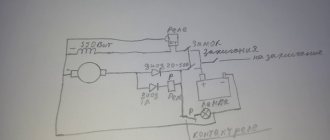
I have a Ural 8.103-10. 1995 There are 3 wires that go to the generator, I disconnected it and forgot which one to connect where) tell me who knows) and also removed the generator and also don’t know how to put it in place, there are 3 rotating (pieces), how can I combine them correctly?
2↑ Reply from mexanik62 04/12/2012 21:27:10
- mexanik62
- Mechanic from the 30s.
- Inactive
- Name: Uncle Vitya
- From: Evpatoria
- Registered: 03-08-2011
- Messages: 10 832
- Reputation: 1 151
- Motorcycle: 12-volt K-750, ZAZ Sens Hatchback