The contactless ignition system of the VAZ 2109 includes a switch, as well as spark plugs, a distributor (distributor), a coil and an ignition switch. The system is designed to supply a spark that ignites the air-fuel mixture into the combustion chamber. It is very important to supply the spark at exactly the right moment in the compression phase of the mixture.
Switch design and malfunctions
The VAZ 2109 switch is one of the key elements of the car’s ignition system. The device is designed to switch current pulses of the required amplitude and duration in the primary winding of the ignition coil, depending on the control pulses of the Hall sensor. It also stabilizes the current from 6 to 18 V, protects semiconductors from overloads and ensures that the ignition system is turned off when the engine is stopped.
The housing provides a connection to ground through a radiator. When the device operates, a significant amount of heat is generated through its radiator. During operation, the radiator should be regularly cleaned of all kinds of contaminants to maintain heat transfer.
Signs of a faulty switch may include the following:
- when the starter is turned on, the engine does not start, there is no spark at the spark plugs;
- the engine starts, but soon stalls at idle;
- The engine runs unsteadily and the spark sometimes disappears.
A malfunction of the VAZ switch is not the only possible reason for the appearance of such symptoms. Such signs can be observed when the distributor fails or contact is lost.
To carry out repairs correctly, a thorough diagnosis is necessary.
Basic Switch Elements
The switch circuit is quite simple, but making this unit yourself is pointless, since buying a ready-made version will be much easier. Installation must be carried out as competently as possible, otherwise the device will not operate correctly. In addition, when using transistors, you need to carefully select them according to their parameters, and for this you need to have high-quality measuring equipment. Unfortunately, for two identical semiconductors, the spread of characteristics can be very large. And this affects the operation of the device.
Diagnostics of device health
It is recommended to carry out in-depth diagnostics of the device at a specialized service. A professional stand will allow you to evaluate the condition of the unit in various engine operating modes in the range from 0 to 8000 rpm. The manufacturer categorically does not recommend diagnosing using artisanal methods. This is dangerous not only for the car’s electrical system, but also for the person trying to carry out such diagnostics.
If the car’s dashboard is equipped with a voltmeter, and the car owner knows how to check the VAZ switch, then a simple way is available to him to preliminary assess the performance of the device. One of the functions of the switch is to turn off the power to the ignition coil when the engine is not running but the ignition is on. With such a shutdown, the voltage in the on-board network increases noticeably. This means that to check the functionality of the device, you should insert the key into the lock, turn it to the ignition position, but do not turn the starter. At this time, you must carefully monitor the readings on the voltmeter.
In the first seconds, the arrow will freeze approximately in the middle of the scale, and after 8-10 seconds it will noticeably move to the right. Since the device worked, the coil turned off, the voltage increased, and the voltmeter responded, then everything is in order. If a switch fails, it usually happens entirely. It is unlikely that the secondary function remained operational, but the basic one failed. So, with a high probability, the device can be considered working.
Repair and replacement instructions
It is worth noting that modern Russian switches are suitable for output key transistors not only of standard production, and in particular KT890A, KT898A1, but also the foreign analogue BU931. It can be implemented either without a housing or in the TO-220 or TO-3 design.
As for the control circuit, the 78.3734 series switches are suitable for:
- 4-channel amplifier type K1401UD2B;
- domestic microcircuit R1055ХП1;
- foreign L497B SGS-TOMSON.
Before replacing the switch or its components, it is recommended to test the integrity of the wiring and connections of the ignition system. Pay special attention to the generator. It is also a good idea to check the voltage from the on-board network to the Hall sensor.
More details on faults and how to repair them are given in the table below.
Alternative diagnostic methods
When there is no voltmeter on the dashboard, you can get out of the situation by doing everything yourself. To do this, you will need a 12 V light bulb and two meter wires with stripped ends. The diagnostic work flow diagram is as follows:
- disconnect the battery, de-energize the electrical system;
- using a size 8 wrench, unscrew the nut and remove the wire from the ignition coil terminal marked “K”, this wire is brown and goes to the clamp marked “1” on the switch;
- connect this wire to one of the test lamp wires;
- Connect the other wire of the control lamp to terminal “K” on the ignition coil;
- connect the battery;
- Turn on the engine starter and observe the condition of the lamp. If the lamp is flashing, the device is working properly. If the lamp does not light, the device is faulty.
There is another simple and reliable way to identify a device malfunction. To do this, you need to install a known-good switch, start the car and check the functionality of the system in all modes. If the system is working normally, then the problem was precisely the failure of this device, and when the same failures occur, the switch has nothing to do with it.
The disadvantage of this method is that you need to have a spare working switch with you. While this is reasonable for long journeys in uncrowded areas, it is exotic for regular city trips.
Price
More details in the table.
And finally, remember that when replacing a powerful switching transistor, it is important to pay attention to the quality of fixation of the part to the switch body. Many beginners make mistakes here or do not apply enough heat-conducting paste. As a result, the device cannot be repaired.
A characteristic feature of the car can be considered its rapid obsolescence, but long life. The most modern car today, in at least two years, will be inferior to other, newer cars with improved characteristics. But even now there are cars from the last century on the roads. Therefore, it is not just interesting, but sometimes necessary, to know at least in general terms what such vehicles are, their structure, features, including such a thing as a simple ignition switch, which significantly changed the capabilities of the car.
Features of repairing the VAZ 2109 switch
Repairing a switch most often comes down to replacing it. Fine-tuning the device is intended only to improve the efficiency of the system. If the device breaks down, the procedure for replacing it is as follows:
- de-energize the vehicle's electrical system, remove the main terminal from the battery;
- disconnect the brown wire from the negative terminal of the battery;
- Use a screwdriver to press out the spring bracket and disconnect the block with wires from the switch;
- unscrew the two radiator mounting nuts and remove the device together with the radiator;
- install a new switch with a radiator;
- connect the connector block;
- place the brown wire under the left nut;
- secure the switch to the VAZ 2109 with nuts;
- connect the battery.
Troubleshooting routers
Author: Alexander Belyavtsev | May 23, 2010 It happens that you need to configure a router without having the necessary software at hand.
photo No. 2 Photo No. 2 clearly shows the supply of power to the circuit; the third wire from the socket goes to grounding the switch body. This circuit is a voltage converter: input voltage - 220V; output voltage - 3.3V.
Some simple setup methods are given using the example of troubleshooting a router. First, you need to connect the device to your computer using an Ethernet cable. Open a browser and enter the router address. The default is 192.168.0.1. The default password and username is admin. If the password has been changed, but you have lost it or forgotten it, then the settings must be reset to factory settings.
To do this, you need to turn on the router and press the Reset button, holding it for 20 seconds. Please note that resetting will delete all current instrument configuration.
To reconfigure your wireless network, you will have to run the setup wizard again. If you are unable to connect to the router settings via the Web interface, then check all cable connections and, if possible, change the connection ports.
What is and what is the principle of operation of the ignition switch
Even on the very first cars, battery ignition systems were used to ignite the combustible mixture, the functional diagram of which is shown in the figure.
This figure allows you to understand that its work is based on the principle of self-induction. When the current flow circuit in the winding of bobbin 3 is broken, a high-voltage EMF is induced in the secondary, causing a spark to appear on the contacts of spark plug 2. The circuit break is caused by the opening of the contacts of breaker 6.
Without touching on the advantages or disadvantages, it should be noted that this scheme worked on the car for a long time. And only the emergence of a new element base gave impetus to the further development of such a device, preserving the original principle of its operation.
We draw up an act for decommissioning of equipment
If the equipment is not suitable for use due to physical or moral wear and tear, damage during installation, or was generally lost for any reason, it must be written off. There is no mandatory form of act for such a case. Therefore, an organization can develop such a primary accounting document independently and consolidate it in its Accounting Policy for accounting purposes. Drawing up a write-off act is usually preceded by an inventory and drawing up an inventory list and a matching sheet (if a shortage of equipment is identified). If it is necessary to confirm the unsuitability of equipment for use, a preliminary report on the technical condition of the equipment for write-off can be drawn up. The technical condition report in this case would be the basis document for write-off. It can be drawn up according to the model of the defective statement, which we presented here. The equipment write-off act is usually drawn up by a commission specially created for this purpose and approved by the head of the organization. The act indicates, in particular, the name of the equipment, its cost, and the reason for write-off. We will provide a sample for the act of writing off equipment.
What could the ignition system switch look like?
The above switch circuit is just one of the options for how the ignition device can be implemented. This is done using:
- transistors;
- thyristors:
- hybrid elements;
- contactless sensors.
The transistor circuit of the switch is discussed above; the thyristor circuit uses energy accumulation in the capacitor, and not in the electromagnetic field of the ignition coil. During operation of the thyristor system, when control signals are received, the circuit connects a charged capacitor to the windings of the coil, through which it is discharged, causing a spark to appear. Without touching on the advantages and disadvantages that this or that circuit has, suffice it to say that any such device provides a significant improvement in all parameters of the ignition system, and the switch over time has replaced conventional battery ignition.
However, it is necessary to note one more stage in the development of the system, and the switch in particular. The use of electronic components and the introduction of a switch into the design of the car made it possible over time to abandon the contact voltage breaker and replace it with a contactless sensor. Such a system, in domestic cars, was first used in VAZ cars, in particular the VAZ 2108. A similar operating principle, when the switch receives signals from a special unit, is implemented on the VAZ 2108 using a Hall sensor.
When considering the options for what the switch device could be, one cannot ignore the development of the ignition system itself. The main principle that is implemented during its construction is to increase the reliability and efficiency of the entire system. This is achieved by using microprocessor systems that use the readings of numerous sensors. To work with such systems, you need at least a two-channel switch, and recently a separate coil and switch for each spark plug. This approach – a two-channel switch (later also multi-channel) allows you to provide:
- more powerful spark;
- elimination of losses in the distributor;
- stable idle;
- improved starting at low temperatures;
- reduction in fuel consumption.
How is BSZ better than contact?
Having carefully read the previous section, you can see that the system uses an inductive non-contact Hall sensor. The advantage is obvious - there is no friction and commutation. For comparison, look at the contact system. In it, the breaker switches the voltage, the value of which is 12 Volts. Whatever one may say, the metal contacts are constantly in contact with each other, gradually wear out, and become covered with soot.
For these reasons, it is necessary to constantly monitor the breaker, adjust the gap, and carry out timely replacement. BSZ is devoid of these shortcomings, therefore, without third-party intervention, the system operates much longer. The Hall sensor fails very rarely, as does the switch. This increases the reliability of the system, but precautions must also be taken, in particular, the connection of the switch to the body must be as tight as possible to ensure effective heat exchange. In addition, BSZ allows you to improve engine performance, increase, albeit slightly, its power, along with increasing reliability.
How to determine if the ignition switch is faulty
The introduction of an ignition switch into the design of a car, especially on domestic cars of the VAZ family, made it possible to increase their reliability. And although the first production car with an electronic ignition system was the VAZ 2108, similar devices began to be installed on many other cars, primarily classics. However, the use of such a rather complex product has led to the fact that finding a malfunction, as well as checking and repairing the switch, has become possible for the most part only in specialized centers. External signs indicating that a malfunction has occurred may include:
- the engine does not start, there is no spark at the spark plugs;
- the engine starts but stalls after a few minutes;
- The motor is unstable; if the switch is replaced with a known good one, the defect is eliminated.
The easiest way to identify a malfunction and test a switch, as already noted, is to install a known-good one. Due to the rather low quality of the switches supplied for the VAZ family of cars, including the VAZ 2108, drivers have to carry additional switches with them to replace the failed one. However, there is also an indirect evaluation principle that allows you to check the performance of the product and identify its malfunction.
To do this, you can use the readings of the voltmeter in the instrument cluster. You need to turn on the ignition, and the needle will be in the middle of the scale, and a little later it will swing to the right (due to the power supply to the coil being turned off when the engine is not running). This arrow behavior indicates that there is no fault in the switch. In the event that there is no voltmeter, a test lamp is required to check the ignition. One end of it is connected to ground, the other to the output of the coil connected to terminal 1 of the switch. If you turn on the ignition, then if the switch is working properly, after a while the lamp will burn brighter.
However, in some cases, the ignition malfunction is not related to a switch failure. It is necessary to check the condition of the wires, first of all, contact with ground and the condition of the connectors. It is also necessary to check the Hall sensor.
The appearance of a voltage switch in the design of a car, including the domestic VAZ 2108, was a natural result of the development of the ignition system. Its further improvement was the use of first dual-channel and then multi-channel switches to improve operating efficiency. » alt=»»>
Checking the 2109 switch yourself on a VAZ, or simply “nine” car is something that sooner or later every owner of this domestic car may encounter.
This small electrical device, if it fails, makes operating the car difficult or even impossible.
In our material we will analyze in detail: what is this switch, why is it needed and how to determine whether it is working?
Content:
Existing types of switches
There are two main types of devices: AC CDI and DC CDI. The first switches were small and simple, using a high-voltage generator in their circuitry. The latter are more common, equipped with four contact groups with minus and plus, as well as separate outputs for the coil and Hall sensor. But the latter function only in the presence of high voltage supplied from an external source.
Switches are also usually classified according to their functional features:
- traditional or stock devices that strictly correspond to the parameters of the car - as a rule, they are installed from the factory;
- sports - they have the ability to increase the upper limit of the number of revolutions of the internal combustion engine, however, this type is the lot of experienced specialists and has the risk of accidents;
- with the ability to adjust the phases of the UZ - an excellent option when you need to equalize the torque of the power plant, improve acceleration characteristics and stabilize engine operation at different speeds.
Of course, switches are usually divided into main types.
Electronic
This type of switch is also called a microprocessor switch with transit keys. It is used to control the converter voltage and reduces the load on the connections, thereby increasing the current capacity.
Advantages of the electronic system:
- possibility of better filling of internal combustion engine cylinders;
- efficient engine output at all speeds.
Hybrid
These systems additionally use a mechanical part - a cam distributor. The electronics are represented by the switch itself and the coil. The unit is very reliable, economical and convenient. For example, if a switch fails, you can switch to an old converter with a slider.
Contactless
A group with transistors, widely used since the early eighties. It replaced the antediluvian classical contact systems. At one time it was considered the most effective, since its performance indicators were much higher than those of other switches.
Dual channel
The same contactless system, but significantly modernized. For example, a conventional BSZ has the same disadvantages of a KSZ - loss of spark energy, instability of idle speed, limitation on adjustment of the SPD, high sensitivity to pollution and humidity. A two-channel system or DBSZ eliminates these disadvantages from the ignition system, providing even higher spark energy through the use of additional coils. Also, problematic moving elements - a slider and a coal - are not used here, and the lid serves only as a protective element. Therefore, it is not subject to burnout.
Interestingly, two-channel ignition was used before. This was implemented on export VAZ-21083. However, switches of this type, also called dual-circuit switches, were not widely used due to the poor quality of the electronics of that time.
One more nuance regarding switches. They may have different outputs. Those with the default number “1” are extremely dangerous for the ignition coils at the moment they experience malfunctions. But the advantage of such devices is that standard converters for contact ignition can be integrated with them.
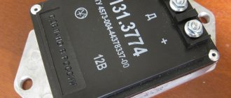
For the second types of switches, in which output “0” is used by default, conventional coils are completely unsuitable. They will get very hot, or the spark will not flow properly. Such a switch includes, for example, the model for BTsZ 131.3734.
The switch is the basis for uninterrupted engine operation
The VAZ 2109 car is equipped with a contactless ignition system.
The system includes spark plugs, four high-voltage wires (one for each spark plug), a Hall sensor, a distributor, an ignition coil and, in fact, a switch.
Rice. 1 Ignition circuit of VAZ 2109 Schematic illustration.
The ignition system generates an electrical impulse (spark), thereby igniting the mixture of fuel and air in the combustion chambers necessary for engine operation.
The switch is responsible for the cyclic supply of pulses to the ignition coil, this is necessary for the proper operation of the entire system as a whole.
Thus, if the switch is faulty, the spark will supply intermittently or be completely absent. It is not possible to drive such a car.
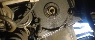
The VAZ 2109 switch itself consists of an aluminum case and a microcircuit installed on it. The device is mounted in the engine compartment and connected by wires to the ignition coil.
Rice. 2 Appearance of the VAZ 2109 switch.
The design of the housing and the mounting method allow the switch to successfully withstand vibrations that occur when the car is moving.
The VAZ 2109 contactless ignition system switch has the following performance characteristics:
- Voltage range 6–16 Volts.
- Operating voltage 13.5 Volts.
- Switching current 7.5–8.5 Amperes.
- A switch in good condition ensures an uninterrupted supply of spark to the cylinders with a crankshaft speed of up to 7000 rpm.
What is harmful about old office equipment that ends up in a landfill?
Any electronic device, once in a landfill, becomes a time bomb . After all, the substances released by household appliances cause irreparable damage to the environment and human health. Let’s take a closer look at the environmental hazards office equipment poses:
- Computer technology.
- The decomposition period of a metal case in nature is more than 10 years.
- A plastic panel will take more than 500 years to decompose, releasing toxic substances throughout this time.
- PVC, a durable material from which the wires practically does not decompose in natural conditions.
- Boards, connectors, and circuits are made of metals that emit hazardous substances when in contact with the environment.
- Printers, scanners, copiers and other MFPs.
- Aluminum and iron oxide are the filling of seemingly harmless cartridges .
- The toner contains cyanide particles that can cause serious allergies and respiratory problems in humans.
- When heated, polystyrene plastic
- Electronic components contain chemicals, metals and compounds that, when exposed to different climatic conditions, release dangerous poisons.
- Faxes and telephones.
- Several hundred years is the decomposition period of a plastic case .
- The wires consist of polyvinyl chloride, which, when decomposed, releases chlorine, dioxins, etc.
- Chemicals and compounds included in boards and circuits are extremely dangerous for the soil and atmosphere.
Old office equipment rotting in a landfill can sit for several centuries, emitting hazardous substances and poisoning the soil and atmosphere. Environmental consequences will affect not only those living today, but also many future generations.
Signs of a broken switch
During the operation of the car, unpleasant symptoms may occur, indicating a malfunction of the ignition system.
A possible reason for this may be incorrect operation of the switch. Here are the most common symptoms that should suggest a possible breakdown of this device:
- Can't start the engine. There is no spark when the starter is running.
- The engine starts and runs normally at low and medium speeds, but cannot be revved up at high speeds. The engine is not running at full power.
- The car stalls when moving away, although it idles stable.
- The engine starts, but does not run for a long time and immediately stalls.
- The engine begins to operate unstably - “triple”, reaching a certain speed level. When cold it can start quite normally.
- The engine may periodically, without any pattern, stall, then work normally again. The battery discharge indicator lights up. The tachometer needle shows sharp changes in the number of revolutions.
Spark ignition principle
Currently, the most common battery ignition system contains a current source in the form of a car battery when starting and a car generator when the engine is running, an ignition coil, which is a transformer with a high-voltage secondary winding, to which a spark-producing spark plug is connected, as well as an ignition distributor (switch). . The operation of the switch consists of periodically interrupting the current circuit of the primary winding of the ignition coil. With each such interruption of the current, its magnetic field, existing at the points of space occupied by the wires of the secondary winding of the ignition coil, very quickly decreases. At the same time, in accordance with the law of electromagnetic induction, a very large vortex electric field arises at the same points in space, the intensity of which creates a high (up to 25 kV) EMF in the secondary winding of the ignition coil, broken by the electrodes of the spark plug. The voltage between them quickly reaches a value sufficient to breakdown the air gap, and then an electric spark jumps, igniting the fuel-air mixture.
Verifying switch operation
Every car enthusiast with a sufficient level of desire and minimal technical skills can check the operation of the switch.
The easiest way to check is to replace the unit with a new one that is known to be good. If after this the problems in the engine operation have disappeared, then we can conclude that the old switch has already served its purpose.
Every car enthusiast can replace the switch independently. First of all, you need to find it under the hood of the car.
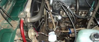
The switch is located in the area of the left (driver's) pillar. It is connected by wires to the coil.
Rice. 3 Engine and organization of the engine compartment of the VAZ 2109.
1 – front glass of the shock-absorbing strut; 2 – water tank; 3 – air filter; 4 – fuel pump; 5 – steering rack; 6 – camshaft sensor; 7 – vacuum brake booster device; 8 – master cylinder of the brake system and its barrel; 9 – switch; 10 – fuses; 11 – engine cooling system tank; 12 – battery; 13 – hood fastening; 14 – ignition coil; 15 – starter; 16 – high-voltage wires; 17 – neck for oil; 18 – engine; 19 – candles; 20 – windshield washer system.
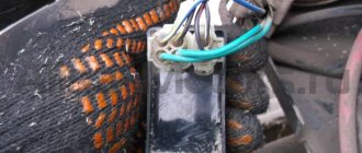
Next, disconnect the negative terminal from the battery. Then you should carefully disconnect the plastic bracket with wires from the switch. To do this, you need to release the spring clip.
Then we unscrew the nuts that secure the aluminum switch housing to the car body. Under the left nut there will be a ground terminal.
Remove the switch from the studs and replace it with a new one. The new one is installed in the reverse order.
Top 5 reasons for switch failure: overload and other reasons
Breakdown of switching equipment can be caused by external and internal factors.
Violation of basic operating rules
Trivial carelessness can lead to failure of the switch. The quality of work is affected by various mechanical influences:
- sudden pulling out of network cables;
- accidental blows to the body;
- falling from a great height.
Among the reasons for damage to internal components, it is also worth mentioning the fire of microcircuits as a result of contact with water or any other liquid.
To protect the switch from the human factor, it is enough to follow the rules of safe operation, described in detail in the user manual.
Low quality software
The problem of insufficiently reliable software is faced by owners of budget switches from unknown manufacturers, as well as users of counterfeit network equipment (counterfeits of well-known brands).
Important: Using the link https://www.moyo.ua/comp-and-periphery/network_equip/kommutatory-nastraiv/cisco/ you can purchase an original Cisco switch based on certified software.
If the software malfunctions, re-flashing the switch can restore functionality.
Electrical network instability
An electrical surge or short circuit is fatal to almost any network equipment. Switches, routers, access points and other devices are especially susceptible to damage during a thunderstorm.
To protect devices from short-circuit currents and sudden voltage drops, uninterruptible power supplies and external stabilizers should be used.
Damage to ports for connecting equipment
If the switch itself, according to visual signs, works without interruptions, but you cannot connect any device to it, the problem lies in the network ports. Most likely, as a result of prolonged use, the “inputs” simply wore out and became unusable.
This problem can be solved at any service center. Specialists will quickly replace damaged ports and restore functionality to the device.
Failure of one of the internal elements of the switch
If the switch stops turning on, you should look for the cause of the breakdown inside. The device’s memory board may have burned out, one of the microcircuits has failed, or the built-in power supply has stopped working.
A trip to the service center or independent replacement of faulty spare parts will help eliminate all these breakdowns.
Don’t panic and immediately after a switch malfunctions, look for a replacement. Most problems can be fixed with much less money spent on repairs than on purchasing a new device.
Automotive Switch Repair | Master Vintik. Everything with your own hands!
If with some malfunctions in the car you can somehow get to the repair point, then with a faulty switch the engine will not start at all. Some drivers often carry a spare switch with them. In this article we will look at the principle of operation, some malfunctions of the car switch and methods for repairing it.
- Often the switch fails due to water getting into it. As a result, the Kr1055xp4 microcircuit (analogous to L497B) fails,
- Due to overvoltage or time, the output transistor type KT8231A1, KT8225A, KT8232A1, KTD8252A, KTD8264A, KTD8267, KT898A, KT8127A1 (analogous to BU941ZP) often fails.
| Name | Type of shell | Analogue | Structure | Pk max, W | Ukb max, V | Uke max, V | Ueb max, V | Ik max (imp), A | h21е |
| KT8127A1 | TO-218 (KT-43) | BU941ZT(ZP) | NPN | 100 | 1500 | 700 | 5 | 5(7,5) | 35 |
| KT8231A1 | TO-218 (KT-43) | BU941ZT(ZP) | NPN | 155 | 350-450 | 350-500 | 5 | 15 | 300 |
| KT898A | TO-218 (KT-43) | BU931ZP/BU941ZT(ZP) | NPN | 125 | 350 | 350 | 15 | 5 | 400 |
| BU941ZT(ZP) | TO-218 (KT-43) | — | NPN | 155 | 350 | 350 | 15 | 15(30) | 400 |
To test the switch, we assemble such a simple stand as in the figure below. We connect a 12 V light bulb instead of the coil.
Normal Switch Operation
When we turn the axis of the distributor with the DH (hall sensor), the light comes on. When we don’t turn it, the light doesn’t light up.
A little about the Hall sensor
A Hall sensor is a magnetoelectric device that takes its name from the name of the physicist Hall, who discovered the principle on the basis of which this sensor was subsequently created. Simply put, it is a magnetic field sensor. There are two types of Hall sensors: analog and digital.
Analog Hall sensors
Analog Hall sensors - convert field induction into voltage, the value shown by the sensor depends on the polarity of the field and its strength. But again, you need to consider the distance at which the sensor is installed.
Digital Hall sensors
Digital sensors determine the presence or absence of a field. That is, if the induction reaches a certain threshold, the sensor outputs the presence of the field in the form of a certain logical unit, if the threshold is not reached, the sensor outputs a logical zero. That is, if the induction and, accordingly, the sensitivity of the sensor are weak, the presence of the field may not be detected. The disadvantage of such a sensor is the presence of a dead zone between the thresholds.
Digital Hall sensors are also divided into: bipolar and unipolar. Unipolar - they are triggered in the presence of a field of a certain polarity and are turned off when the field induction decreases.
Bipolar - react to a change in field polarity, that is, one polarity turns on the sensor, the other turns it off.
Hall sensor check
- Measure the voltage at the sensor output. It should be more than 0.4 V.
- Check for a spark when the ignition is turned on. To do this, you need to short-circuit pins 1 and 2 of the switch with a wire.
- Replace with a known good one.
A little about switches
Some switches have different "logical" outputs. Some, for example 131.3734-01, have a logical “1”, while others have a “0”.
Those who have “1” by default (this is when the device shows 12 volts or close to them by default between the “+” and “Short” contacts) actually run the risk of burning the coil at the moment when the ignition is turned on and the engine is not running, creating a one-sided potential inside the coil and without discharging it, you can thereby feel with your hand the rapid heating of the coil. The created potential begins to discharge only when the engine is running.
The advantage of such switches is that you can use ordinary (native) coils for contact ignition practically without disturbing the old coil connection circuit. In this case, the switch is inserted into the gap in the wire that went from the breaker contact to the coil. The distributor is simply replaced and a switch is added.
In a switch, for example BSZ 131.3734, the default logic “0” is observed. If you set the coil of the switch kit 131 3734 with logic “1” by default, then the coil will get terribly hot. Or, on the contrary, on a coil intended for a switch with logic “1”, put a switch 131 3734 - logic “0”, then either there will be no spark, or it will be very weak, or the switch may even be damaged.
P O P U L A R N O E:
- Digital speedometer for bicycle
- FREQUENCY-VOLTAGE converter circuit
- How to connect fog lights yourself?
It is important for a cyclist to know the speed of the bike and the distance traveled while moving. Determining the length of a bicycle ride is quite simply solved using a mechanical device, commercially produced by industry and installed on one of the wheel forks. The mechanical speed indicator of a bicycle is not widely used. Read more…
Frequency-voltage converter on LM331
In amateur radio circuits, there is a need for frequency-voltage conversion, for example, to measure frequency with a voltmeter (multimeter), a sensor that responds to changes in frequency, etc. More details...
About parallel and serial connection
According to the new Rules, you need to drive a car during the day in the same way as at night with a light on. Available with low beams, running lights or fog lights. Today we’ll look at how you can connect fog lights to your car. Fog lights will also be useful in fog. To save money, you can connect the fog lights yourself. There is nothing complicated about connecting fog lights, and anyone can handle this task! Read more…
Popularity: 35,042 views.
Source: https://www.MasterVintik.ru/remont-avtomobilnogo-kommutatora/
Armored wires
High voltage wires serve to transmit pulse voltage from the ignition coil to the fixed contacts of the distributor cover, and from there to the central electrodes of the spark plugs. The VAZ 2107 has five such wires. Structurally, each of them consists of a conductive core, several layers of insulation (PVC or silicone) and tips.
The set consists of five wires: four transmit voltage to the spark plugs, and the fifth serves to supply it from the ignition coil to the distributor
Wire faults
Armored wires can have only three faults:
- breakdown of the insulating layer;
- breakage of the current-carrying conductor;
- core wear.
Failure of one or more high-voltage wires at the same time is accompanied by the following symptoms:
- “triple” of the motor;
- its difficult to start;
- drop in power unit power;
- increase in the amount of fuel consumed.
How to check high voltage wires
Checking armored wires consists of determining the integrity of their insulation and establishing the resistance of the current-carrying conductors. To assess the condition of the insulating layer, it is enough to remove the wires, clean them of dirt and inspect them by twisting and bending them in your hands. If during such a check it is discovered that at least one of them has cracks, severe abrasions, or traces of electrical breakdown, the entire set should be replaced.
Long-term operation of high-voltage wires leads to wear of the current-carrying core, as a result of which its resistance changes up or down. Naturally, this affects the magnitude of the transmitted voltage and spark energy.
The process for measuring wire resistance is as follows:
- Turn on the ohmmeter and set it to the range 0–20 kOhm.
- We connect the probes of the device to the ends of the current-carrying wire.
- We look at the ohmmeter readings. Serviceable wires, depending on the manufacturer and service life, can have a resistance in the range of 3.5–10 kOhm. If the indicators are different, we change the wires as a set.
The core resistance should be in the range of 3.5–10 kOhm
Video: checking armored wires
Examples of malfunctions of various equipment
The list of typical reasons for writing off computer equipment for this article was provided by Profit LLC.
Profit LLC has been operating in St. Petersburg and Leningrad Region since 2005. The cost of work to assess the technical condition of fixed assets with the issuance of a write-off act starts from 250 rubles. for one piece of equipment .
Work with Customers under decommissioning and disposal agreements is carried out by the head of the technical department, Shorin Roman Viktorovich - tel. +7 (921) 352-88-88, E-mail
If you have any questions, you can ask them in the comments to this article, we will definitely answer them.
Computer malfunctions for write-off
- motherboard failure,
- significant corrosion of printed tracks,
- mechanical damage to elements,
- hard drive is faulty
- the controller has failed,
- there are unreadable sectors on the surface,
- the video card is faulty,
- processor does not start,
- the power supply does not start,
- the pulse transformer has failed,
- Computer repair is not advisable due to the incompatibility of computer components with modern software.
Printer faults for write-off
- the power supply is faulty,
- the power transformer has failed,
- control board is faulty,
- the carriage drive belt is torn,
- broken carriage cable,
- failure of the printer print head,
- formatter board malfunction,
- The motor of the cartridge carriage drive unit is faulty.
Monitor faults for write-off
- loss of kinescope emission,
- The switching power supply has failed,
- the tracks on the printed circuit board are burnt out,
- oxidation of contact groups,
- line scan unit is faulty,
- electrical breakdown of a line transformer,
- matrix is faulty,
- failure of the inverter module,
- malfunction of backlight lamps,
- there are dead pixels,
- control board is faulty,
- the power supply starts up.
Laptop faults for write-off
- microcrack on the motherboard,
- the controller power circuit is faulty,
- hard drive malfunction,
- the controller has failed,
- there are unreadable sectors on the surface of the hard drive,
- the power supply burned out,
- the pulse transformer has failed,
- mechanical damage to the power connector, keyboard keys,
- matrix damage,
- burnout of the inverter board,
- the inverter is faulty,
- short circuit of the pulse transformer.
Reasons for writing off an electric kettle
- the heating element has failed (broken circuits of the spiral),
- the seal of the housing is broken,
- Thermocouple and switch malfunction.
UPS faults for write-off
- the inverter is faulty,
- breakdown of power transistors,
- failure of the pulse converter,
- control board is faulty,
- interturn short circuit in a transformer.
TV malfunctions for write-off
- interturn short circuit in a line transformer,
- the frame scanning unit is faulty,
- broken filament of the kinescope,
- line scan unit is faulty,
- electrical breakdown of a line transformer,
- switch board is faulty
- interturn short circuit of the transformer in the power supply,
- failure of the backlight lamp,
- processor board defect,
- oxidation of matrix control cable connectors.
Refrigerator faults for write-off
- the compressor has failed,
- the engine is faulty,
- The radiator seal is broken,
- door seals have dried out,
- damage to freon pipes.
Air conditioner faults for write-off
- the control unit has failed,
- The power controller does not start,
- the pump motor is faulty,
- the tightness of the supply pipes is broken,
- broken freon line circuits,
- damage to heat exchanger radiators.
Scanner faults for write-off
- the control board is faulty,
- the control controller is faulty,
- the carriage drive gearbox is faulty,
- wear of gear teeth and shaft seats,
- The scanning element is faulty.
Reasons for writing off a vacuum cleaner
- the engine failed,
- the tightness of the hoses is broken,
- brush wear,
- damage to the housing and rollers.
Reasons for decommissioning drills and screwdrivers
- the engine failed,
- rotor coil breakage,
- gearbox is faulty
- gears and drive shafts are worn out,
- mechanical damage to the clamping mechanism.
Reasons for decommissioning a water heater
- the heating element has failed,
- open circuit of the heating element,
- the control unit is faulty,
- The seal of the housing is broken.
Reasons for decommissioning a heater
- the heating element has failed,
- The radiator seal is broken.
Cell phone malfunctions for write-off
- The radio channel unit has failed,
- oxidation of the processor board,
- processor failure,
- keyboard is faulty,
- buttons sticking,
- microphone is faulty
- speaker is faulty
- the display is broken,
- mechanical damage to the screen matrix.
Malfunctions of a USB flash drive for write-off
- is not recognized by the computer as a result of failure of the controller chip,
- mechanical damage to the board,
- oxidation of contact groups,
- connector damage.
Reasons for decommissioning a plotter
- Plotter power supply faulty,
- control panel is faulty
- failure of the controller board,
- the ink supply system is faulty,
- pump failure,
- destruction of ink supply tubes,
- the carriage drive unit is faulty,
- print head failure,
- failure of the plotter controller board as a result of ink getting onto the contact groups from a leaking cartridge.
Reasons for writing off the copier
- the power supply is faulty,
- failure of the high-voltage unit,
- The thermoblock drive has failed,
- wear of the Teflon and rubber shafts of the fuser block,
- the heater drive motor is faulty,
- wear of paper path mechanisms,
- board is faulty
- formatter board malfunction,
- broken corotron filaments,
- oxidation of microcircuits on the controller board,
- failure of the interface board.
Reasons for writing off printing equipment
- image transfer tape is worn out,
- the power transformer of the power supply is faulty,
- conveyor unit malfunction,
- failure of the image forming unit,
- deformation of the main drive shafts,
- switch board is faulty
- failure of the control controller.
Reasons for writing off a cartridge
- the transfer unit is faulty,
- shaft contacts are destroyed,
- the axes of the magnetic shaft drive gears are broken,
- the tightness of the mining bunker is broken,
- the cartridge chip is faulty,
- The contact group of the cartridge has failed.
Reasons for discharging the battery
- the terminals of the contact groups have failed,
- significant corrosion due to leakage of electrolyte,
- the seal of the housing is broken,
- the battery life has been exhausted,
- increased self-discharge,
- sulfation,
- breakage and short circuit of plates.
Reasons for writing off a calculator
- mechanical damage (keys sticking) to the keyboard,
- the indicator is broken,
- The controller board has failed,
- indicator is faulty,
- There is no backlighting for some elements.
Reasons for decommissioning a lamp
- destruction of the lamp socket,
- significant deformation due to heating,
- the mounting bracket is damaged.
Reasons for writing off an exercise bike
- the gearbox has failed,
- gears and drive shafts are worn out,
- broken axles,
- significant deformation of the body,
- failure of the control and indication board.
Reasons for writing off furniture
- deformation of furniture elements as a result of moisture,
- significant surface damage as a result of thermal overheating,
- deformation of the seats of the connecting elements,
- mechanical damage to hinges and damage to fastening points,
- the appearance of a network of cracks on the surface,
- wear of the fastening elements of the drawers and legs,
- destruction of elements of supporting structures,
- deformation of the seat and back,
- gas lift malfunction,
- wear of the piastres and the swing mechanism,
- damage to the crosspiece structure.