How to adjust the rear gearbox of a Ural motorcycle
ASSEMBLY OF MAIN TRANSMISSION ASSEMBLY WITH DIFFERENTIAL OF MOTORCYCLES “DNEPR” AND “URAL”
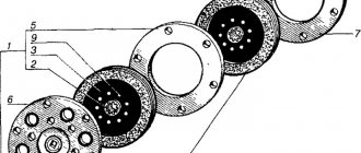
When assembling the assemblies and parts of the main drive (see Fig. 58), it is necessary to ensure the clearances and tensions specified in Table 20.
The angular contact bearing 12 and the inner ring of the needle bearing 10 are pressed onto the drive gear 11 of the main gear until it stops. Lubricate the inner cavity of the outer ring of the needle bearing with technical petroleum jelly and install it on the inner ring pressed onto the drive gear.
The studs are screwed into the main gear housing, and the size from the end of the crankcase to the end of the stud must be 18.5. 20 mm. Heat the crankcase in an electric furnace or water bath to 75.80°C and press the sleeve 7205104 into it with a hand press (Fig. 60), which serves as the outer race for the hub bearing of the driven gear, and then the drive gear 59 (see Fig. 58) assembled with bearings, also up to the stop. Place the adjusting washer 13, 14 on the angular contact bearing 12 and tighten it with a nut 60 until it stops, having previously placed a spacer 15 under it concentrically with the relative nut. Longitudinal bearing play is not allowed.
When assembling the driven gear, the ball bearing 48 is pressed into the hub until it stops, the driven gear 52 is put on the hub 51, aligning their holes, the locking plates 50 are installed and the bolts 49 are tightened to capacity, adjusting their edges until the plates bend.
To assemble the elastic coupling of the cardan shaft, the cage lock 28 is opened and put on the coupling 30 in the annular recess. Press the holder 28 onto the coupling and secure it with the holder lock along the annular groove. The coupling sleeve 29 is pressed into the coupling and flared on both sides with a flaring radius of 2.5 mm and a depth of 0.5. 1 mm from the edge of the coupling.
When assembling the cardan joint, screw the oiler 20 into the crosspiece 21, insert it into the ears of the cardan shaft yoke 22, having previously put the sealing ring 24 and clips 37 on the finger of the crosspiece. The fingers of the crosspiece are positioned perpendicular to the oiler. Needle bearings 38 are filled to half the volume with Litol-24. Press one needle bearing into the eye of the propeller shaft fork, as shown in Fig. 8.6. A locking ring is installed into the socket of the eye with the bearing; when pressing, make sure that the finger of the cross fits into the bearing without knocking the needle out of place, and to the depth of the eye without pinching the cross. A splined fork is put on the free fingers of the cross and the remaining two needle bearings are pressed into its ears. The locking rings must sit tightly in the recesses of the forks and reliably hold the bearing races from falling out. The rotation of the propeller shaft yoke and the splined yoke on the crosspiece, in the absence of clearance in the axial direction, should be free, without jamming or distortion. Crunching and jamming of bearings when rotating the hinge is not allowed.
During the general assembly of the main gear (see Fig. 58), 32 rollers are placed in the groove of the hub assembly 51 and lubricated with Litol-24. The rollers are compressed with a bushing 75005104 B (for Dnepr motorcycles) or 7205104 (for Ural series motorcycles). To select the thickness of the package of adjusting washers 13 in the final drive housing assembly with the drive gear and on the hub of the driven gear assembly with the rollers. install a special (reference) ring. Check the gap between the wheel teeth with an indicator - the gap should be 0.22. 0.45 mm. Measure the size from the end of the ball bearing of the driven gear to the plane of the crankcase connector. Select adjusting washers; the thickness of their package is determined as the difference between the thickness of the gasket 7205107 and the indicator reading, taken with a plus or minus. The adjusting washers are selected so that the gap in the gear pair of the assembled transmission is 0.1. 0.3 mm. After this, remove the driven gear from the main gear housing, remove the special (reference) ring from the hub and select the spacer ring 54 according to the following data:
Do-it-yourself tricycle assembly from the Urals
Before starting work, it is necessary to think through the design of the future tricycle and the location of all elements. Ideally, make a drawing of the future vehicle.
Important design points:
- All joints must be reinforced.
- Car cups are welded to the top beam. It also serves as a support for shock absorbers.
- Frames are welded to the central beam, which serve as footrests for passengers and also support the suspension bump stops.
- The base for the pedal weights is the lower transverse tube, which is attached to the frame.
- A support for the gearbox is also made on the transverse frame.
The main difference between a tricycle and a motorcycle is that the engine is located at the rear and therefore the center of gravity of the vehicle is shifted back. When accelerating, such a tricycle rears up a little. Below you can see a diagram of how to convert a Ural motorcycle into a tricycle.
Location of tricycle parts
As we have already said, the engine of a Ural tricycle is not located on the main axis, like in motorcycles. It is placed between the rear wheels, because of this, when accelerating quickly, the tricycle easily rears up. But this is a much safer event than on a motorcycle and adds adrenaline and entertainment to the trip.
Engine
As a motor, you can use a native motor from the Urals or take a car engine. The main parameter of choice is its capacity between the rear wheels. Be sure to securely fasten it in at least three places. Most often, if the power unit is in good condition, then you don’t even need to do anything to it. And if the engine is old, then you can replace the radiator or some other elements.
Depending on the engine you choose, you will also have to change the exhaust system by installing one muffler for each cylinder.
When converting a motorcycle from the Urals into a tricycle with your own hands, the gearbox is usually installed on the left side, because you usually need to hold the steering wheel firmly with your right hand. You'll have to think a little about how to connect it to the engine, because now the gearbox will be located at a much greater distance from it.
Suspension
The standard motorcycle suspension will have to be redone due to the fact that the load on the wheels in the Ural moto tricycle is distributed differently.
This is done using two consoles and two large springs (aircraft springs are ideal, but car springs will also work). The consoles are connected by levers through which the front axle passes.
Powerful springs are needed because when moving, a huge load is placed on the front wheel and suspension. The remaining springs can be left as standard motorcycle springs.
Battery
A separate frame is usually welded under the battery, which is attached between the engine and the driver’s seat. All the main details are thus arranged in one place. And if you attach panniers to the tricycle, they will completely hide all the important elements.
Coloring
Since a do-it-yourself tricycle based on the Urals is assembled from different parts, as well as other motorcycles and cars, all the parts turn out different and therefore need painting. After painting, it is advisable to apply a clear varnish and polish. And metal elements are chrome plated.
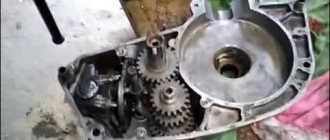
Photo report: Assembly of the gearbox (box) of the Ural motorcycle
In the article: Step-by-step disassembly of the gearbox (box) of the Ural motorcycle, it has already been said that we are faced with the task of assembling at least one working copy of the gearbox from three control units of unknown condition. All three available gearboxes were disassembled, the internal parts of each of them were subjected to thorough diagnostics, both visually and with special measuring tools.
As a result, two gearbox housings did not pass the inspection because they were seriously damaged. In two gearboxes, parts of the reverse gear engagement mechanism were either completely or partially missing; one gearbox was an old model and, moreover, had a “dead” foot start mechanism. In general, we somehow managed to scrape together more or less serviceable parts, only for one gearbox.
Before final assembly of the gearbox, we thoroughly wash the housing, and while the bearings are not yet installed in the mounting holes, we adjust the gear shift mechanism. Adjustment of the gearshift mechanism is done as follows: Place a standard gasket on the body of our gearbox, put a cover with a pre-assembled gearbox on the body, tighten a couple of bolts on the gearbox cover.
We take a flashlight, shine it through the holes into the gearbox housing and, in accordance with the factory instructions, adjust the thrust bolts (marked with arrows) of the gear shift mechanism. It is best to adjust this mechanism before the bearings are installed, otherwise when you look inside, where did the locking ball get into? That's it, no way...
We place the gearbox cover on some blocks and insert the foot start mechanism into it, then we take the secondary shaft in our hand and put the first gear gear and one splined clutch on it.
We put the clutch for engaging the first and second gears on the shaft, with a groove (marked by an arrow) to the first gear gear.
We put the second and third gear gears on the shaft; there should be a washer between the gears.
We put a splined coupling on the shaft, then put on the clutch for engaging the third and fourth gears and put on the fourth gear gear.
We place an oil deflector washer on the secondary shaft bearing.
We connect the secondary and primary shafts and, holding the shafts with our hands, insert them into the gearbox cover.
We install the forks of the gear shift mechanism into place.
We install the rod of the forks and gear shift mechanism into the cover until it stops.
We insert the pin into the bracket for the reverse gear engagement mechanism.
We insert the pin into the reference groove of the plate of the reverse gear engagement mechanism, correctly orient the reverse gear and insert the bracket rod all the way.
After the final assembly of the gearbox, we must check that the gears are engaged correctly and the clutches are engaged correctly. Gear clutches must mesh with the gear splines for the entire length of the splines - without exception. It is also worth noting that the forks of the gear shift mechanism, with any gear engaged, should have a slight free play, that is, not be clamped, as if “floating”.
We put an adjusting washer on the secondary shaft, which ensures the axial play of the secondary shaft in the range: 0.4-0.6 mm.
Install the pin into the gearshift ratchet.
We degrease the connector surfaces, place a new gasket on the sealant, and insert guide pins into the holes (marked with arrows).
We take our gearbox housing with a pre-installed secondary shaft bearing, check the functionality of the retainer ball (marked with an arrow), the ball must have the correct shape and move freely back and forth, apply sealant to the connector and install it on the cover, when installing the housing, do not forget to install the ratchet pin gear shift mechanism into the groove of the fork, gear shift foot shaft.
We twist all seven bolts on the gearbox cover crosswise, unfold it, take the thrust flange of the foot start mechanism, lightly put it on the shaft, turn it so that the return spring tendril goes into the hole, pull the return spring to the desired force, tighten the standard bolts and core their hats.
4WHEELS
There are many options on how to make an ATV with your own hands. It is important to decide what you want to get as a result of your work and what funds you have. Let's consider a simpler rear-wheel drive option.
From a Ural motorcycle, or from an IZH
For the base you will need:
— two front hubs from a rear-wheel drive passenger car (Zhiguli classic, Moskvich);
— rear axle (preferably from a car of the same brand from which the hubs were taken, so that the discs match the mounting holes);
— driveshaft or axle shaft (depending on the design);
— front suspension arms (if desired, you can make completely homemade ones);
- steering tie rod;
— pipe (square thick-walled or round water pipe approximately ¾ inch);
Homemade ATV - today it’s easy to make!
This is the main thing. A bunch of other little things will be needed as the work progresses.
We completely disassemble the motorcycle. We need a clean frame without handlebars or shock absorbers.
We draw drawings, or use ready-made ones and decide which rear suspension option suits us:
— hard without shock absorbers (cheaper and less labor-intensive, but more suitable for tall soft tires);
— on springs with shock absorbers;
Without shock absorbers
We cut off the rear part of the frame along with the pendulum fork mount. We lengthen the frame and rigidly weld the bridge using gussets and jibs.
It is important to consider the following points:
— the axle gearbox, in case of replacement, should be removed without problems;
— the direction of rotation at the output of the Ural gearbox is reverse. Those. When installing, the road bridge must be turned over, otherwise it will go backwards.
Video about a homemade ATV
On springs with shock absorbers
We leave the rear suspension pendulum together with the original silent blocks. We weld the bridge to the fork, be sure to reinforce the seams with wide gussets, otherwise it will tear out along with the metal of the bridge. Instead of a cardan, in this case, you need to use an axle shaft from Oka, or VAZ 08, 09, etc. Because when using the original rear fork, it is required to transmit torque at a large angle, which the driveshaft crosspieces cannot provide. With this design, springs with shock absorbers can be left in their old place.
On springs
If your needs require a cargo ATV with a body, it is better to use springs for the rear suspension. In this case, a frame for the body is welded from a square thick-walled pipe (with a cross-section of approximately 70×40). The length is no shorter than the spring, and the width is equal to the size of the bridge. This body frame is connected to the motorcycle frame by means of jibs, which must be correctly positioned to ensure sufficient torsional rigidity of the structure.
The base of such an ATV is larger than the above-mentioned designs, since the rear axle is located further. But it becomes possible to use a car driveshaft: serial or shortened. The cardan is connected to the box by a Ural rubber coupling, and to the bridge by a native flange, through the hinge cross.
If an Izhevsk donor is used for an ATV, it is more convenient to abandon the differential. In this case, a large driven sprocket is installed on the axle, and the drive is carried out by the original chain.
Front suspension
The design of the front suspension is almost the same for the ATV from IZH and from the Urals. To attach the swingarms, the motorcycle frame is extended at the front. It is important to ensure that the turning wheels do not touch the engine cylinders. Therefore, on the Ural frame the wheels should be further forward.
To increase geometric cross-country ability, the suspension arms should be as long as possible. Therefore, it is better to make them yourself rather than use serial ones from the car.
The steering column can be made from a Ural cardan. At the bottom, two steering bipods are welded to it, located side by side, each for its own steering rod: for the right and left wheels. The hubs are attached using the original ball hubs.
Four-wheel drive ATV from Oka
Using the power unit from Oka, you can make an all-wheel drive ATV. It is better to cook the frame for it from scratch, taking into account the mount and size of the engine. The front suspension leaves more space for installing a front wheel drive gearbox, which can be made independently from the “classic” rear axle. To do this, cut off the “stockings” of the bridge and remove suitable axle shafts from the VAZ 08, 09 from the differential.
It is important to think through every detail so that as many standard parts as possible are used, which will greatly facilitate subsequent repairs.
The power unit is deployed according to movement. The axle shafts now become cardan shafts, transmitting torque to the front and rear axles.
It is more convenient to operate the gearbox manually.
Finishing
First of all, these are wings! Still, the technique is extreme, they must be strong and wide. Having sufficient skills in working with metal, you can give an ATV such an appearance that a homemade one will look no worse than a factory one. Some shapes can be given using polyurethane foam. After hardening, it is easy to process, putty and paint. A reliable trunk will add rigidity to the finishing of the body. By attaching a trunk to it, you can increase the size of the usable area for transporting goods.
Blade, trailer
An ATV is an excellent base for installing all kinds of attachments useful on the farm. A homemade ATV can be equipped with a snow blade. The size of the blade depends on the dimensions and weight of the ATV. If the quad is made on the basis of the Urals, it will pull a knife 1.5 m wide and half a meter high. The material for the shovel is 3 mm steel.
Even a children's ATV has enviable cross-country ability; Moreover, a large and heavy one can tow a car trailer.
The time, money and effort spent on making a homemade ATV will more than pay off. After all, in addition to adrenaline, you get a hard worker on the farm who can replace a small tractor.
Did you like the article? Subscribe to the channel to stay up to date with the most interesting materials
Gearbox UAZ 469. device, repair and photo
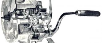
Shaft 11 rotates in a roller bearing, which is installed in the housing cover of the UAZ 469 wheel reducer, and in a bronze bushing inside axle 18. At the end of shaft 11 there is a mechanism for disconnecting the front wheels of the vehicle. The device consists of movable rods 14 and 15, which are located on the splines of the shaft and bolts 17 and 16 with a spring and a ball.
These movable couplings are connected by their external splines to the internal splines of the drive flanges 13 and 14, which are bolted to the wheel hubs. To reduce wear on the metal surfaces of the front axle parts of the UAZ 469 and save fuel when driving on paved roads, it is recommended to disconnect the front wheel hubs at the same time as disconnecting the front drive axle.
To perform this disconnection, remove the protective caps 16 and 18. Then unscrew the screws 16 and 17 from the hole in the shaft 11. Place the coupling in such a position that the groove of the signal ring “a” on its plane is in the same plane with the end of the flange. When the coupling is installed in the required position, tighten the protective caps.
The wheels must be secured by screwing in bolts 16 and 17. The bolts must be tightly tightened. Disabling and enabling must be done simultaneously on two wheels of the front drive axle. DO NOT engage the front axle with the wheels disabled!
Gearbox Maintenance
The rear axle gearbox operates under increased loads. The service life of the rear gearbox depends on periodic maintenance and operating mode.
A sign of a malfunction of the rear axle gearbox, which should be diagnosed and, if necessary, repaired, is the appearance of noise. Gearbox noise is a hum that is easily felt while driving and which bothers the ears when driving over long distances.
Usually, when gearbox noise appears, you always have to make a major overhaul or replace it completely.
Depending on what gear the car is driving in and at what speed, the noise may vary.
What gearbox noises can be:
- incessant noise from the rear of the car;
- noise during car acceleration;
- noise when turning;
- noise when braking.
The procedure for repairing or replacing a complete unit:
- Prepare a standard set of keys.
- Remove the wheels.
- Remove the brake drums.
- Remove the pads.
- Unscrew the axle shaft mountings with a socket wrench.
- Remove the axle shafts.
- Disassemble and remove the driveshaft. We do this in this order:
- Place marks on the cardan flange and gearbox flange to avoid imbalance after assembly.
- Unscrew the bolts that secure the shaft.
- During assembly, use new nuts to avoid possible damage on the road (cardan shaft breakage).
- Unscrew the gearbox mountings to the rear axle using a socket wrench.
- We install a new gearbox or repair it.
- After assembly, fill in new oil for the gearbox.
Drain the oil from the gearbox by unscrewing the drain plug.
If while driving there is a hum around the rear wheels, then adjustments need to be made. The hum comes from constant loads.
Have you installed a rear view meter? If yes, then where? You can install a rear view camera in the bumper, in the trunk handle, or above the license plate. But what is the best place to keep your lens clean for as long as possible?
We carry out diagnostics in this order:
- Remove bearings.
- Remove the seals.
- Remove the satellites.
- Remove flanges.
- Remove the axles.
- All removed parts must be washed in gasoline or kerosene.
- Inspect visually and, if damage to at least one tooth is detected, the part must be replaced.
Information about the stages of modernization of axle gearboxes for 6x6 vehicles.
- 1984 – introduction of an additional bevel gear bearing (an angle was introduced to lubricate the bevel gear bearing and the gearbox configuration was changed).
- 1996 - two additional holes were introduced on the gearbox flange for mounting to the bridge Ø 19 mm and the diameters of 7 (seven) holes were increased from Ø 15 mm to Ø 17 mm.
- 1999 – the material of the adjusting nut 375-2403040 was changed instead of KCh and is made of 35L steel.
- 2001 – a locking plate for fixing the differential nut 375-2403042 was introduced, increasing the size of the locking part from 46 mm to 51 mm.
- Since 2003 A gearbox with a fixed side cover and a square is offered as spare parts (for example, a gearbox with i = 7.32:
- 4320-2302007 – front axle gearbox
- 4320-2402007/2502007 – rear/middle axle gearbox)
The gearbox is supplied unpainted and preserved for spare parts. The serial production number and production date are stamped on the gearbox housing flange. A plate with the gear ratio and car model stamped on it should be installed under the cup cover bolt 375-2402135.
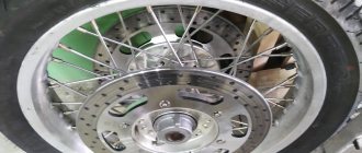
We understand the motorcycle axle and adjust it
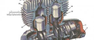
The rear axle is designed for the correct transfer of torque to the wheels through the cardan drive. It is with its help that the wheels rotate while the motorcycle is moving.
The standard rear axle of a Ural motorcycle has axle shafts, a carrier beam, a differential and a final drive. The left part of the beam is a forged cover with an axle housing, and the right is a cast iron crankcase with another part of the axle housing. On the left side the casing is welded, and on the right side it is firmly pressed inside. The crankcase itself with the cover is located in the center of the landing board and is secured with bolts. The outer part of the axle housing is connected to flanges. The Ural motorcycle axle must be equipped with lubrication of the drive gear bearings. For this purpose, special channels are used in the crankcase, of which there are two: in the middle and lower parts. In the first case, it is necessary for draining the oil, in the second - for filling. Everything happens through special holes, which are covered with screw plugs.
To limit upward movement of the crankcase, the neck is equipped with a special boss that serves to support the buffer in the body. It is this buffer that acts as a limiter. The rear axle of a Ural motorcycle can overheat, and in order to slow down the change in pressure level when the oil inside the crankcase heats up, a breather is needed - a special safety valve.
For the correct functioning of the part, the drive gear must be fixed in a special position. The correct choice of adjustment ring will help with this. It mainly differs in thickness (from 1.33 to 1.73 mm). In addition, as a preventative measure, it is worth preloading the bearings of the drive gear, which is equipped with the Ural motorcycle axle, and also checking the accuracy of the clearance of the side gears. All this is done during the adjustment process during the collection of spare parts.