02.11.2021 13,442 VAZ 2109
Author: Ivan Baranov
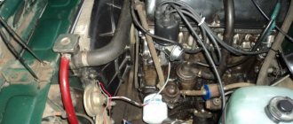
Modern cars are mostly equipped with an internal combustion engine. In order to cope with various unforeseen situations on the road, you need to know the structure of the machine. The article describes the operating procedure of the VAZ 2109 cylinders, as well as possible malfunctions in the operation of the power unit.
[Hide]
The operating order of the VAZ 2109 cylinders
Quite often, car owners ask the question why they need to know the operating order of the VAZ 2109 cylinders if the car is working normally.
The fact is that knowledge of the operating principle of the internal combustion engine (ICE) is necessary in order to detect the problem in time and take measures to eliminate the malfunction. Timely measures taken will protect the engine from serious damage. The VAZ 2109 uses a 4-cylinder engine. There are four strokes in engine operation:
1. “Intake”, in this stroke, fuel is supplied to the system, which is mixed with air. At this stage, the cylinder is filled with the working mixture. 2. "Compression". At this stage, the working mixture is compressed due to the movement of the piston in the cylinder. 3. "Expansion". The compressed air-fuel mixture is ignited by a spark generated by the spark plug. As a result of combustion of the mixture, the resulting gases expand and, under high pressure, push the piston down, this movement is transmitted to the crankshaft. 4. "Release". At this stage, through the open exhaust valves, exhaust gases enter the vehicle's exhaust system.
To ensure smooth engine operation, various operating patterns are used to determine the sequence of cylinder operation. The most common scheme is 1-3-4-2; it is this combination that is used in the VAZ 2109. The numbers correspond to the accepted numbering of the cylinders, in which the front part of the engine is usually used as the reference point.
Thus, the working cycle of the VAZ 2109 internal combustion engine is represented by the following sequential actions:
1. In the 1st cylinder there is a downward movement, a working stroke, that is, combustion of the working mixture and expansion of gases. 2. “Compression” occurs in the 3rd cylinder, the piston moves up. 3. In the 4th cylinder there is an “intake”, the piston moves down, and the working mixture is pumped into the cavity. 4. “Exhaust” is carried out in the 2nd cylinder; exhaust gases leave the cavity through the exhaust valves.
Now let's look at several cases of malfunctions in the operation of the VAZ 2109 engine. In order to find out the cause of the breakdown, you should use the following algorithm of actions:
• Start the engine and go to idle speed. Listen to the sounds of exhaust. If uniform, periodic popping noises are observed, then most likely the cylinder is not working due to suction, a faulty spark plug, reduced compression or lack of spark. • Inspect the spark plugs; there should be no traces of soot, oxidation or moisture. The gap between the electrodes should average 0.8-0.9 mm. • Replace the spark plug set. • Check the condition of the high-voltage wires of the ignition system. The insulation must be intact, and the contacts must not be oxidized or burnt. If the wires are damaged, they must be replaced. • Inspect the rotor and distributor cap. The lid must be intact, without cracks and clean, without traces of soot. The carbon contact must not be worn or damaged. The rotor must also be intact and have no signs of burnout. All faulty elements must be replaced. • If, after the actions taken, interruptions in the operation of the cylinders continue, then you should contact a service station for a full diagnosis and adjustment of the ignition system, which should be carried out on a stand. • It should be noted that normally the compression should be above 1.1 MPa. If fluctuations within 0.1 MPa are observed in one of the cylinders, then it is necessary to urgently repair the engine itself.
Thus, it is quite obvious that knowledge of engine operation will allow timely repair work and avoid serious breakdowns.
BTSZ device
The ignition system of the VAZ 2109 consists of:
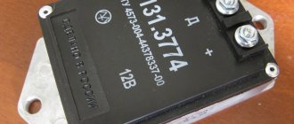
- Switch 3620.3734;
- Spark plugs A17DVR;
- Distributor sensor 40.3706;
- Ignition coils 27.3705;
- Ignition switch;
- — A locking device that prevents the starter from being turned on again until the ignition is completely turned off;
- — Locking and anti-theft device.
Design features and operating principle:
- The operating principle of the VAZ 2109 ignition system is based on the Hall effect.
- The sensor-distributor shaft receives torque from the engine camshaft and is located horizontally.
- Spontaneous shutdown of the ignition system occurs 2-8 seconds after turning the ignition key to the extreme left position and the engine is turned off.
- During the operation of the SZ, the switched current is equalized in the case when the voltage in the network varies from 6 to 18 V.
- At low engine operating frequencies, thanks to a special system built into the switch, the time of accumulation of electricity in the ignition coil is regulated, and the current is limited.
The ignition system of the VAZ 2109 operates at a voltage of up to 26 kilovolts, the duration of the spark discharge varies in the range of 1.6-2.0 ms and during this time 35 - 50 MJ of energy is released.
Distributor.
Sensor-distributor.
Comprises:
- There are two types of ignition timing regulators - vacuum and centrifugal;
- A voltage pulse sensor that regulates the operation of the switch.
interruptions in the operation of the engine of a VAZ 2108, VAZ 2109, VAZ 21099
During interruptions, the car engine idles unevenly, the engine does not develop sufficient power, and it consumes gasoline more. Engine failures on a VAZ 2108, VAZ 2109, VAZ 21099 are usually explained by incorrect carburetor adjustment, a faulty spark plug or one of the cylinders, or air leaks into one of the cylinders. It is necessary to find the fault and, if possible, eliminate it.
1. Start the engine of a VAZ 2108, VAZ 2109, VAZ 21099 car and leave the engine idling. Go to the exhaust pipe and listen to the sound of the exhaust. The sound should be even, “soft”, of the same tone. Popping sounds from the exhaust pipe at regular intervals indicate that one cylinder is not firing due to a failed spark plug, lack of spark at the plug, excessive air leakage into one cylinder, or a significant reduction in compression in the cylinder. Popping noises occur at irregular intervals due to improper carburetor adjustment, ignition, severe wear or dirty spark plugs. If popping noises occur at regular intervals, you can try to replace the entire set of spark plugs yourself, regardless of the mileage and appearance of the spark plugs, but it is better to do this after contacting a car service center to diagnose and adjust the carburetor and ignition system.
2. If the popping sounds are irregular, stop the engine and open the hood. Check the condition of the ignition system wires. High-voltage wires must not have insulation damage, and their tips must not be oxidized. If there is damage to the high-voltage wires, replace the faulty wire.
Maintenance schedule
To avoid having to carry out expensive overhauls of the Lada Samara 2114 yourself, you should follow the manufacturer’s recommendations for servicing the internal combustion engine:
| Maintenance object | Time or mileage (whichever comes first) |
| Timing belt | replacement after 100,000 km |
| Battery | 1 year/20000 |
| Valve clearance | 2 years/20000 |
| Crankcase ventilation | 2 years/20000 |
| Belts that drive attachments | 2 years/20000 |
| Fuel line and tank cap | 2 years/40000 |
| Motor oil | 1 year/10000 |
| Oil filter | 1 year/10000 |
| Air filter | 1 – 2 years/40000 |
| Fuel filter | 4 years/40000 |
| Heating/Cooling Fittings and Hoses | 2 years/40000 |
| Coolant | 2 years/40000 |
| Oxygen sensor | 100000 |
| Spark plug | 1 – 2 years/20000 |
| Exhaust manifold | 1 year |
The principle of operation of a four-stroke power plant
You can understand why it is important to connect high-voltage wires correctly if you study the principle of operation of the power plant. The carburetor or injector of the VAZ-2109 operates on approximately the same principle, since both power plants are four-stroke.
- First, the cylinder volume is filled with the fuel mixture and exhaust gases. This process is called "inlet".
- The engine then goes into compression. With it, the valves are closed, and the crankshaft and connecting rod move the piston upward. The mixture of fuel and air is transferred to the combustion chamber.
- During the expansion stage, the ignition is switched on and a spark appears. It ignites the fuel mixture, resulting in the formation of gases. They put pressure on the piston, causing it to move down. This force is transmitted through the connecting rod to the crankshaft.
- The process is completed by the “release” of exhaust gases through the exhaust system.
In order for the engine to operate smoothly and without jerking, the processes must take place in a certain order. This, first of all, concerns the order in which the cylinders are put into operation.
Finding the ignition moment in the ignition
On engine 402, ignition adjustment occurs according to the following algorithm and order:
- The crankshaft occupies a spatial position corresponding to 5 degrees of advance in ignition of the fuel mixture;
- This position can be easily achieved by aligning the mark on the pulley with the recess on the motor block;
- The coincidence means that the power plant has marked the end of a full piston stroke.
With the distribution sensor removed, adjustments are made as follows:
- I remove the spark plug from the head of the combustion chamber of the cylinder, which is listed as No. 1 in the order of fuel ignition;
- I cover it with a sheet of paper and turn the engine crankshaft;
- The air pushed out by the piston blows off the sheet, which indicates that it has reached the vertical maximum, from which the stroke begins;
- Then, using the keys, I set the octane corrector scale to 0.
Engine workflow through cylinders
The cylinders are activated as follows:
- In the first there is an upward movement. The gases expand and the mixture of air and fuel burns.
- In the third, to carry out the compression procedure, the piston rises.
- In the fourth, “injection” occurs - the piston moves down and at the same time a mixture of air and gasoline enters the cylinder.
- In the second cylinder, the piston rises and takes the upper position so that gases escape through the valve system. After which the exhaust gases are removed from the power unit.
Based on the principle of operation of the cylinders, their activation diagram looks like this: 1-3-4-2. It is important to connect them correctly so that the cylinders work in that order.
How to connect wires correctly
When replacing high-voltage conductors, they are first connected to the ignition distributor. The distributor cover is convenient in that it is always installed in one position. There is a special mark on it, thanks to which it will not be difficult to place the part in place. Before connecting the wires, inspect the cover. It must be intact, since if cracks appear, the performance of this unit is not guaranteed.
The mark on the distributor cover is located next to the wire socket of the first cylinder. The firing order of the cylinders is slightly out of order (1-3-4-2) due to the ignition slider. It moves around the circle (distributor) counterclockwise. It is precisely by this principle of movement of the slider that it is easy to remember the order of the wires. They need to be connected to carburetor and injection VAZ-2109 according to the same principle. On the distributor cover, connect the wires according to the principle of movement of the slider, this is the only way you can set the ignition correctly:
- the socket of the first cylinder is located at the mark;
- the third one is connected at the very bottom;
- on the same line with the socket of the first, there is a place for the wire to the 4th cylinder;
- at the top point the second cylinder is connected.
Valve location
In the VAZ-2109 model, the designers changed the previously familiar system with a camshaft chain drive.
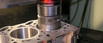
Despite the simplicity of the old design, it was noisy and required additional adjustments after a short period of time. In the nines, the shape of the upper part of the piston was changed, and special recesses were added for the valves.
An important adjustment task is also to align the camshaft and crankshaft on the same axis so that they rotate together.
The intake and exhaust valves are located in a certain order, this should be taken into account when adjusting
When adjustment is necessary
Valve adjustment is required when problems occur with the engine or after passing a technical inspection. Experienced car owners can quite accurately determine the cause of a power unit malfunction; the main signs are the following:
Valve adjustment is also required after every 25-30 thousand kilometers . During this time, some parts wear out and structural gaps increase. Diagnostics can be done at a service center; this service is inexpensive.
Preparatory work
From the adjustment tool you will need:
- set of wrenches;
- special device for adjustment;
- measuring probe;
- several adjusting washers;
- screwdriver;
- tweezers;
- valve cover gaskets.
Before starting the repair, set the car to the handbrake and engage any gear. One of the front wheels must be suspended so that the crankshaft can turn easily.
The procedure is as follows:
- Raise the hood.
- Disconnect all pipes from the cover.
- Remove the windshield wiper housing.
- We unscrew the spark plugs.
- Remove the front timing belt cover.
Tip: To monitor the current position of the piston, you need to use the viewing window.
For many VAZ models, the adjustment technology is not much different. Those who have already had experience of working with previous versions will find it easy to understand. The gaps are set according to the order in which the cylinders operate. The exhaust valves are 1, 4, 5 and 8 when counted from the camshaft drive belt. We use the following table in our work:
We use the table to correctly determine the cylinder number based on the crankshaft position
Tip: Before starting the adjustment, it is worth placing additional marks on the pulley every 90 degrees.
- Before adjustment, it is necessary to align the piston of the first cylinder. To do this, turn the crankshaft so that the marks on the pulley and the rear belt cover coincide.
The marks on the timing belt pulley and rear cover must be at the same level - Using a 17 key, turn the camshaft 3 teeth clockwise. This is necessary so that the camshaft cams move away from the pushers.
We install the camshaft so that the fists move away from the pushers - We test the gaps with an adjustment feeler; the tool should move under the influence of slight forces.
Using a feeler gauge, determine the amount of clearance on the first cylinder
If the gaps are increased or decreased, the following actions must be taken:
- We install the adjustment device on the bearing housing.
Installing the adjustment device - Turn the pusher towards you.
- Using the lever, we fix the pusher in the desired position.
We press the pusher using the lever and fix it in this position - Use long tweezers to remove the old washer.
Using tweezers, remove the old adjusting washer
The next task is to select a new washer of optimal thickness. Calculating this parameter is simple; we use the formula below:
- H = A + (B – C), where
- H – thickness of the new washer,
- A – thickness of the removed washer,
- B – gap size,
- C is the required gap.
Install a new washer and remove the retainer. We check the gap with a feeler gauge and, if necessary, select another washer of the required thickness. The finished set of washers contains products with a pitch of 0.05 mm. This procedure is carried out for each engine cylinder.
Features of modifications with an injector or carburetor
A considerable part of the owners of the VAZ-2109 model are equipped with an injector. When adjusting here, one important fact should be taken into account - thermal expansion.
When the engine is running, metal parts increase slightly in size, which leads to a decrease in clearances. Therefore, adjustments must be made only on a cold engine.
This way you can correctly measure the gap and select the adjusting washer.
The procedure for connecting high-voltage wires VAZ
First, let's decide which of the four cylinders is first?
The first cylinder in front-wheel drive VAZs is located closer to the timing belt. If you look at the engine from the front, the first cylinder is the leftmost). And then everything is simple - from left to right - 1, 2, 3, 4.
In rear-wheel drive VAZ Classic and Niva, the first cylinder is located closer to the front bumper of the car.
General tips for connecting high-voltage wires
Checking high-voltage wires. To check the wires, you will need a multimeter tester. Check the resistance of the wires - it should be no more than 20 KOhms (in practice, the longest wire of cylinder 1 has a resistance of up to 10 KOhms).
If the wire resistance is more than 20 Kom, it must be replaced. Carefully inspect the wires for chafing on parts of the motor or other wires. In case of significant abrasion, replace the wire.
In case of minor abrasion, it is possible to lay the wire so that it does not rub and fix it in this position.
Laying wires. Do not try to connect the wires in a bundle. Disassemble the wiring harnesses, release the wires from the plastic holders. Connect the high-voltage leads to the corresponding cylinder spark plugs.
Lay the wires so that they do not rub against each other, engine parts, or hoses. Avoid sharp bends and tension on the wires.
After connecting all the wires, secure them into the bundle with special comb holders included in the delivery kit.
The procedure for connecting I/O wires to a VAZ carburetor (2108, 2109, 21099)
- The central wire from the distributor cover always goes to the ignition coil (bobbin).
- The outlet of the distributor cover, which faces towards the front of the car, is connected to the first cylinder.
- The outlet of the distributor cap, looking down, is connected to the third cylinder.
- The outlet of the distributor cap, looking rearward, is connected to the fourth cylinder.
- The outlet of the distributor cap, looking up, is connected to the second cylinder.
- The procedure for connecting high-voltage wires to a VAZ Classic, Niva with a carburetor and distributor.
Central wire from the ignition coil (bobbin)
1 cylinder - above the vacuum corrector. Next, clockwise, the order is 1-3-4-2.
Injection VAZ produced before 2004 with an old-style ignition module (4-pin low-voltage connector)
Actually, on the module body it is already indicated which cylinder the pins correspond to - but we duplicated them in red in case the module gets completely dirty, and you might not be able to see it in the photo.
Injection VAZ produced after 2004 with a new ignition coil (3-pin low-voltage connector)
As with the old-style ignition modules, the new coils are also marked with pins corresponding to the cylinders. But the connection order is different from the order on the old-style ignition module. Be careful.
Numbering of cylinders in different types of internal combustion engines
As for the standards for numbering combustion chambers, there are none. The way they are numbered in the internal combustion engine is influenced by the following factors:
- Type of drive;
- ICE type, block layout;
- Transverse or longitudinal arrangement of the unit under the hood;
- Side of rotation.
On standard front-wheel drive cars with a transversely mounted engine, the numbering begins on the timing side. So, near the timing belt there is the first cylinder and then all the others. The latter is located near the checkpoint.
Examples
In multi-cylinder V-twin engines, the first cylinder is located in the bank on the driver's side.
In American-made engines, the combustion chambers and their numbering may differ and defy logic.
So, for in-line fours and sixes, the first cylinder may be near the radiator, while on all other models the numbering begins towards the interior. If the numbering is reversed, then the cylinder closest to the passenger compartment is considered first.
The French are very original and use two methods of numbering the combustion chambers of internal combustion engines.
- On inline fours, the numbering starts from the flywheel.
- If it is a V-shaped six, then the row closest to the radiator is the first three cylinders, and the row closer to the passenger compartment is the last three.
The procedure for connecting high-voltage wires on a VAZ 2109 (carburetor, injector)
The ignition module on injection VAZ 2109 is deservedly considered one of the most complex electrical components. If the injectors have a module, then the carburetors have the simplest coil.
The actual, but incredibly important task of the module is the generation of high voltage current, which can reach 30 thousand watts. The current follows high-voltage wires to the spark plugs, which create a spark to ignite the air-fuel mixture.
The classic ignition coil is one of the components of the module, so the system works on a much more complex principle than on carburetors.
High voltage wires
Often, the main difficulty when repairing a carburetor VAZ 2109 is the reconnection of high-voltage wires that were previously disconnected from the distributor cover. It's also an ignition distributor.
The difficulty is that many people forget the connection procedure or simply do not know. But in practice, returning high-voltage wires is much easier than understanding the ignition module used on the injection VAZ 2109.
By following a few simple rules, you can easily return the wires to their rightful places.
- The ignition distributor cover is installed in its place, that is, on the distributor, only in a single position. Therefore, even if you wanted to, you won’t be able to confuse anything here. Otherwise the lid simply won't fit.
- There is an installation mark on the cover, which indicates the location of the wire socket from the first cylinder.
- The wires must be connected in the following sequence - 1, 3, 4, 2. Move counterclockwise when looking at the distributor cover from the side of the expansion tank.
If for some reason there are no installation marks on the VAZ 2109 carburetor distributor cover, just follow the connection principle shown in the image.