01/12/2021 17,983 IZH
Author: Ivan Baranov
Many owners of Izhmash equipment set the ignition themselves. This process is not difficult if you understand the structure of the system and the principle of operation. The article provides instructions on how to set up the ignition on a motorcycle, including the IZ Jupiter 5.
[Hide]
In what cases is ignition adjustment necessary?
During the operation of the vehicle, the owner faces many problems.
The most serious failure is related to the engine. In order to spend significant funds on major repairs, it is necessary to monitor the technical condition of the motorcycle and carry out preventive work, including adjusting the valves and valves (video author - Hana Rulyu). If you do not monitor the SZ, then the motorcycle engine may not reveal its full potential and will not work at full capacity. This can lead to a reduction in its service life. An ignition adjustment is necessary if the engine is running poorly, the muffler or carburetor is firing. True, before setting up the SZ, you should make sure that the cause of the malfunction is in it.
It happens that the flywheel bolt, which connects the two halves of the crankshaft, comes loose, begins to play and does not work well. Sometimes he even cuts the key.
Setting up the SZ may be necessary after repairing lock 5. The installation and connection itself are carried out according to the diagram.
Guide to setting up BSZ on a motorcycle
How to install electronic ignition on Izh Jupiter 5
To configure the system on a motorcycle, it is advisable to use devices with a scale of up to 15 volts and an internal resistance of up to 0 kOhm. Thanks to the electronic device, adjusting the unit will not take much time and effort. The terminals from the device must be connected to the Hall sensor. The procedure for setting up contact ignition without using auxiliary devices is shown in more detail in the video below (the author of the video is the Han Rulyu channel).
So, for proper tuning, place the cylinder piston in a position that provides the most optimal spark formation. Any cylinder can be used. Then the ignition is activated, and the modulator device must be turned in the direction of movement of the rotor with the crankshaft. Rotation is carried out until changes are visible on the voltmeter screen. At the moment when you can catch a spark, the position of the curtains should not be changed. As for the modulator device, it must be securely fastened to the generator shaft; a fastening screw is used for this.
During setup, you should in any case short-circuit the high-voltage circuits to the motor housing. This is done so that when using a short circuit, the system does not overload, which can ultimately lead to failure of the BSZ. In addition, the engine cannot be stopped when removing the spark plug caps.
After the adjustment is made, the performance of the system must be checked. If you place the cable being tested approximately 7-8 mm from the power unit and then try to start the engine, a spark should jump out. As you can see, in general, the procedure for setting up a node is not particularly complicated, but it requires care and the right approach, so the above recommendations are still worth considering. In addition, one should not forget about safety precautions, since incorrect actions can lead to a short circuit in the wiring and failure of the unit as a whole.
Carburetor - removal and disassembly
It is possible to partially disassemble the carburetor (removing and washing the throttle, repairing the drive, etc.) without removing it from the engine.
1. Place the motorcycle on the center stand.
2. Remove the protective covers.
3. Shutting off the fuel supply, disconnect the fuel hose from the carburetor.
4. Use a screwdriver to loosen the clamp and disconnect the rubber air filter pipe from the carburetor.
5. 10 mm
Unscrew the mixture corrector nut.
6. Remove the corrector plunger assembly.
7. Disassemble the corrector plunger.
8. Pulling the cable sheath upward, unscrew the throttle valve cover.
9. Remove the throttle valve assembly. Cover the hole with a clean cloth.
10. To replace the cable, you need to compress the damper return spring, and, pushing the cable down, remove its end from the cut in the damper needle nut.
1. 12 mm
unscrew the two bolts securing the carburetor adapter pipe to the cylinder. We remove the carburetor with the pipe, being careful not to tear the paronite gasket.
2. Hold the bolts with a 12mm
, unscrew the nuts securing the adapter pipe
with a 13 mm
. We remove the pipe.
1. Using a screwdriver, unscrew the two screws securing the carburetor cover.
2. Remove the float chamber. There is a paper gasket underneath, be careful not to tear it.
3. Using a thin drift, carefully knock out the float axis.
4. Use thin pliers to remove the axle.
5. Remove the float along with the locking needle.
8 mm socket wrench
We turn out the seat of the shut-off valve.
7. Using a screwdriver, unscrew the jets of the main dosing system and the idle system.
8. 6 mm
turn out the additional jet.
9. 12 mm
We turn out the fuel-emulsion nozzle of the main dosing system.
10. Turn out the “quantity” and “quality” screws.
13. We wash all carburetor parts, except gaskets and rubber parts, in acetone or solvent for nitro paints. We clean all channels and jets with copper wire or toothpicks soaked in solvent, and blow them with compressed air from the compressor.
It is unacceptable to clean carburetor jets with steel wire, needles or any other tool.
We assemble the carburetor in the reverse order, while lubricating the rubber o-rings, threads and gaskets with engine oil or BSK brake fluid containing castor oil.
We tighten the “quantity” and “quality” screws until they stop. Then we unscrew the “quality” screw one turn (preset), and unscrew the “quantity” screw five to seven turns.
We check the operation of the shut-off valve. When the carburetor is oriented with the throttle channel down, the air supplied by the mouth into the inlet fitting should not pass through the valve.
Adjusting the position of the needle of the main dosing system is carried out by rearranging the lock washer in the grooves of the needle:
- washer to the left - enrichment of the mixture; - washer to the right - lean mixture.
Required Parts
Correctly setting the equalizer on a Sony radio
In order for the ignition system to work correctly, a number of auxiliary parts are required. They are listed below:
- Switch for BSZ VAZ cars. You should not choose exclusively from the low price segment. The Astro switch has a lot of positive reviews;
- Hall Sensor. The best option for Jupiter 5 is a similar manufacturer VAZ. By purchasing it in branded packaging, you protect yourself from counterfeits;
- Ignition coil with two terminals. You should choose between the gazelle engine number 406 or Oka with an electronic ignition system;
- A pair of silicone armor wires with rubber caps;
- The modulator is a butterfly-shaped plate made of iron.
Modulator
The most difficult stage is the production of the modulator
It is important to maintain the required shape. The more reliably the required dimensions are observed, the lower the likelihood of problems occurring after implementing the system, that is, there will be no need to adjust it using a file
The ignition timing must match on any cylinder used.
The bolt hole must be located in the middle. Otherwise, the engine operation will not be synchronized. It is also recommended to check the integrity of the crankshaft bearings. If you find defects, you should immediately replace it.
The contact ignition is not able to work normally if the bearings are damaged. The thickness of the part should not exceed one and a half millimeters. If it is thin, it will not be possible to avoid deformation, and if it is thick, it will come into contact with the surface of the hall sensor housing.
To create the plate, it is allowed to use any material except steel. Aluminum and others should not be used as they are not magnetic. The drawing that must be followed can be found in the public domain. The presented diagram will be useful to those people who decide to modernize the vehicle ignition device. Below are methods for installing electrical ignition devices in Jupiter.
It must be turned by a professional turner. He will make a simple disk and draw on it the markings of elementary distances between the corners. Then, in accordance with it, you will cut out the necessary sectors at home. The cost of the modulator is seventy rubles.
It is not advisable to use an ordinary plate, since its width is less than twelve millimeters. This will not be enough to fully accumulate the energy resource in the coil. Of course, it can be installed, but achieving four thousand revolutions per minute will become impossible.
In addition to the above you will need:
A stud with an applied thread of seven millimeters, pitch 1, as well as a pair of nuts with washers of the corresponding parameters. The priority material for these components is brass. This is explained by the least magnetization of the plate from the generator rotor.
If you use a standard bolt, then difficulties may arise with the implementation of the ignition. The bolt tends to follow the modulator as it is tightened. However, it is necessary to observe the leading indicator, maintain the same position of the rotor and modulator, and tighten the bolt. It is advisable to use a pin, since many are not able to perform all the necessary actions in total;
A set of wires with connectors for ignition without contact from VAZ. This part can be purchased or made with your own hands.
General recommendations
When considering how to set up a K-65 carburetor, it is necessary to take into account a number of general recommendations. They must be performed before the process. All setup work must be carried out in accordance with the manufacturer's instructions. For owners of the presented vehicles who do not have experience in making adjustments, it is recommended that before starting work they carefully study all the requirements of the device creators.
The carburetor must be in good working order. If there is any abnormality in its system operation, it is necessary to carry out system maintenance.
If necessary, the system will need to be thoroughly cleaned. All consumables are replaced with new seals. The air filter must be clean. If necessary, it must be washed. In some cases it will need to be completely replaced.
When adjusting the carburetor, the engine must be warm. To do this, you can drive several kilometers along the highway. Only after this can you begin the procedure described below.
Features of electrical equipment
Correctly setting up a speaker amplifier
Despite the unification of parts with other models, the IZH Yu5 wiring diagram was chosen for battery use.
We are talking about a contact ignition system, which, if the battery is dead, immediately creates problems for the owner:
- Starting the engine is difficult;
- The engine runs intermittently;
- Driving at low speeds further drains the battery.
Therefore, many owners prefer to upgrade their ignition system with their own hands to a more progressive one - a contactless electronic type. It should also be noted that repairing the wiring of IZ Jupiter 5 should there be a desire for such an upgrade (see also the article about the wiring diagram of IZ Planet 5).
Transition to a contactless ignition system
Over the years of operation, the owners of IZH Jupiter 5 have developed more than one instruction for altering the electrical network. And almost all of them are based on elements from other domestic motorcycles (see also the features of the Ural motorcycle wiring diagram).
But there is a more progressive way in which:
- The generator and wiring remain on IZ Jupiter 5;
- Minor modifications are made to the electrical circuit;
- The battery remains for servicing auxiliary systems.
Ignition system modernization
We are talking about modernizing the ignition system with the combined use of elements from the VAZ-2108 car and the Planet 5 motorcycle.
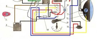
At the same time, the wiring diagram for IZ Jupiter 5 remains the same:
- Two Hall sensors are installed;
- Two electronic switches are connected to them (items 1 and 2 - from VAZ). Each sensor-commutator pair covers 1 cylinder;
- Two ignition coils from a motorcycle of the IZh family.
In the diagram above, the numbers indicate:
- Spark plug;
- Reels Planet 5;
- G8 switches;
- Hall sensors from the "eight";
- Egnition lock;
- Accumulator battery.
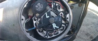
Modification of the generator
This technology for switching to a contactless ignition system is interesting because the motorcycle owner does not need to buy a new generator designed to work in an electronic ignition system. Accordingly, the cost of rework will be minimal.
Enough:
- Make a modulator that will interrupt the circuit;
- And install it on the generator (on the rotor shaft).
A metal plate with a hole drilled in it for a mounting bolt can serve as such a modulator-chopper.
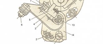
Photo of the only element that you have to make yourself
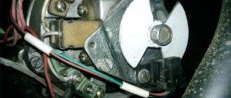
The modulator installation procedure is as follows:
- The modulator plate (in the diagram below under No. 2) is installed under the mounting bolt;
- Slightly attracted to him;
- By rotating the crankshaft, set the piston to TDC;
- We set the ignition timing;
- Tighten the plate with the mounting bolt.
The electrical wiring of IZH Jupiter 5 remains unchanged when altering the generator.
Changes made by owners
The unreliability of individual components and faulty wiring on IZ Jupiter 3 forced the owners to delve into all the intricacies of the modernized elements.
And the first to cause numerous complaints were changes in the primary circuit of power supplies:
- Battery;
- Generator.
As well as ignition systems and circuits for lighting devices of the trailer module - a cargo-passenger stroller. In most cases, the reason for the refusal was a banal manufacturing defect.
Battery charging system
Given the total shortage of spare parts for motorcycles that existed in those years, unplanned failure:
- battery;
- voltage regulator relay;
- ignition coils;
left the owners without transport for a long time. In addition, poor-quality assembly of individual elements led to unstable operation of all systems. This forced me to improve and polish the factory defects with my own hands (for example, see how to modernize the wiring diagram of IZH Planet 5).
General information
IZ Jupiter 3 uses (BSZ) 1137.3734, intended for all models equipped with a 12-volt generator. The ignition coil module for Jupiter 4 or another model makes it possible to select the appropriate operating mode of the motor thanks to the serial connection of the output wires.
The device as a whole improves the technical parameters of the vehicle thanks to:
- improved engine starting at low temperatures;
- more stable operation of the power unit, which is achieved as a result of reducing the asynchrony of spark formation, as well as by optimizing the SZ advance angle in accordance with engine speed;
- reducing the level of toxicity of exhaust gases, fuel consumption, as well as reducing deposits on spark plugs;
- stable start of the power unit even on a battery that has run down to 6 volts, provided that certain models of ignition coils are used;
- easier installation and maintenance of the system as a whole.
Technical specifications
- Overall length 2,115 mm.
- Overall width 780 mm.
- Overall height 1,025 mm.
- Ground clearance 135 mm.
- Dry weight of the motorcycle is 160 kg.
- Maximum speed 110 km/h.
- Fuel tank capacity 18 l.
- Cruising range on the highway is 160-180 km.
- Fuel consumption on the highway is no more than 4 liters per 100 km.
- Fuel: Gasoline with autol 10-18 in a ratio of 25: 1
- Fordability 300 mm.
- Engine Stroke 58 mm
- Cylinder diameter 61.75 mm
- Number of cylinders 2
- Engine displacement 347 cm3
- Compression ratio 6.8
- Maximum power 18 hp. With.
- Air cooling
- Lubrication system combined with fuel
- Carburetor type K-28ZH
Multi-disc clutch, in an oil bath with an automatic release mechanism. The gearbox is four-speed, two-way. Motor transmission is a rollerless double-row chain, gear ratio - 2.57. Transmission from the gearbox to the rear wheel is a roller chain, gear ratio - 2.33. The frame is tubular and welded. The front fork is a telescopic spring type with hydraulic shock absorbers. Rear suspension pendulum spring with hydraulic shock absorbers Type of brakes drum Type of wheels easily removable, with tangential straight spokes. Tire size 3.25-19″
Installation process
It won’t take much time to replace the ignition, maybe a day. The necessary parts can be removed from the Oka vehicle. Electronic ignition is a set of wires, a generator, a two-terminal ignition coil, a Hall sensor and a switch.
There is no need to make any changes directly to the generator itself. You just need to remove the cams and where there is space, attach the Hall sensor
It is very important that the modulator plate passes through the slots of the sensor itself. Thanks to the modulator plate, smooth ignition operation is ensured
Unstable sparking is often caused by an incorrect design of the so-called magnetic flux contactor. In this case, you need to carefully study its placement in relation to the sensor. Overlapping of the magnetic circuit or magnet is unacceptable in the open state of the contactor, while the closed state of the contactor implies complete overlap of these two elements. If this is not the case, then most likely the sensor will emit weak signals to the switch. As a result, unstable engine operation will be observed.
To make a modulator you will need a steel disk with a cutout of 0.8-1 mm
It is important to maintain a ratio of closed to open periods of 2:1. The angle of the cutout in the modulator depends on the type of main power unit
If the main power unit is 1-cylinder, then the angle is 120 degrees. On 2-cylinder engines, an angle of 60 degrees is maintained. The width of the cutout starts from 11 mm and more, but not less. You should also know: a spark occurs when the modulator “opens” the sensor. This is very important when setting the ignition timing.
Before installing electronic ignition on the IZH Jupiter 5 motorcycle, check that there are no large plays on the generator shaft. If they are, you should replace the generator bearings in order to get rid of the “bumpiness”.
Fuel level
Adjusting the K-65 carburetor begins with measuring the amount of gasoline in the tank of the float section. To do this, you will need to prepare a certain list of tools. Almost every home craftsman has them. The tool will be required during the process of dismantling the carburetor.
When the device is removed from the slots, you will need to remove the cover from it. It covers the float chamber. Next you need to take a ruler. The float has a special tongue. It needs to be unbent and bent to make adjustments. Due to this, the fuel level in the chamber will change.
You will need to place a ruler on the connector plane. Next, the tongue must be adjusted correctly. The strip on the float should be at 13 mm. The deviation is ±1.5 mm. The floats themselves must be level. The adjustment must be made very precisely. The operation of the carburetor depends on this.
Making ignition elements for IZH Jupiter 5 with your own hands
You can manufacture individual elements and make electronic ignition for Izh Jupiter 5 with your own hands. To do this, you will need to make your own modulator. The quality of its manufacture determines the reliability of the entire plant.
The modulator is made perfectly symmetrical. A fixed curtain should cover 30 degrees of the area when it is rotated. Once again, it must be emphasized that the modulator is the defining link in the motorcycle ignition system. The smooth operation of the engine is determined by this small device. If the modulator is properly manufactured, then its shutter should not, in the open state, block the magnet and magnetic circuit of the Hall sensor.
The closed state must ensure their simultaneous closure for the passage of magnetic flux. The switch must receive clear pulses of a certain size from the Hall sensor; ensuring this condition is the task of the modulator.
To perform electronic ignition on Izh Jupiter 5 with your own hands, you also need to make a plate for attaching the Hall sensor. BSZ does not require periodic adjustment of the ignition timing. But for initial adjustment it is necessary that the Hall sensor be able to rotate. The plate must have slots.
The Hall sensor itself, together with the plate, is installed on a corner, which can also be made independently.
All the main elements for installing electronic ignition on the Izh Jupiter 5 motorcycle have been manufactured. You need to buy an ignition coil, purchase a switch and a Hall sensor. These BSZ elements cannot be made independently. You will also need a mounting wire. It is advisable to change the spark plugs - the spark may be weak on them. After all the issues have been resolved, the last thing left to solve is how to install electronic ignition on the Izh Jupiter 5.
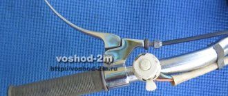
Ignition switch Voskhod - central switch
Switch 124005490201 is used as a central software switch that provides the necessary switching of lighting equipment on a motorcycle. The switch has three operating positions >, >, > in accordance with the following operating modes:
- in position > – the generator sensor circuit is shorted to ground, which ensures the engine stops.
- in position > (driving during the day) – the ignition circuit is turned on, the direction indicator circuit operates (when the direction indicator switch is on) and the brake signal circuit (when the brake pedal is pressed);
- in position > (driving at night), two circuits are switched on:
- a) a circuit of speedometer backlight lamps, license plate lighting and city driving (through a throttle, which serves as a device that complements the parametric control of the generator);
- b) headlight lamp circuit A6-32+32 (via the light switch on the steering wheel).
Caring for the central switch comes down to periodically checking the reliability of the switch in the headlight and cleaning the moving and fixed contacts from dust and dirt by washing them in gasoline.
Contactless ignition on Izh Jupiter 5.
If you are the owner of a more modern and beloved BSZ motorcycle on Izh Jupiter 5, then in addition to all its well-known advantages, ease of customization will also be added. To begin with, we need to unscrew the spark plugs and, without removing them from the spark plug caps, lean them against the ribs of the cylinder, then catch the T.M.T. one of the pistons and rotating the crankshaft back lower the piston by 2.6 mm. When the advance is set, we move on to the modulator.
This element must rotate freely, due to which we must “catch” the moment of spark formation (on the spark plug) with the ignition on. Next, you need to very accurately fix the resulting position by pulling the modulator. Now let's move on to the next cylinder. We also place its piston in the top position, and then unscrew it, lowering it by 2.6 mm. Now, turning the crankshaft by the generator nut, we look at the ignition. If it matches, then everything is set, if there are deviations, then we proceed as follows: for early spark formation, loosen the lock nut of the modulator and set the ignition in the manner described above, then move on to the option when the ignition is later.
With late ignition, the edge of the modulator grinds down until, with the advance set, a spark is formed at the right moment. Finally, leaving the spark plugs on the cylinders, we crank the engine using the kickstarter, determining the evenness of the spark plug formation “by eye.” You can more accurately monitor the accuracy of the settings only by running the engine.
Installing electronic ignition on Izh Jupiter 5 yourself
How to install the modulator and Hall sensor so that the BSZ system works correctly was described above in the text. A new ignition coil, which has two outputs, is installed in place of the old coil. The high-voltage wire from each spark plug goes to the corresponding coil fastening elements.
Switch - in any place protected from water. Correct installation of the BSZ elements will ensure sparking for the Jupiter 5 engine in any weather.
After installing all the equipment elements, the contactless ignition on the IZh must be configured and checked for functionality. First of all, we set the ignition timing. The use of an ordinary light bulb as “dialing” and control equipment is not allowed. It does not respond to electronic impulses.
You need to use an electronic tester as a voltmeter. We measure the voltage at the Hall sensor. We connect the “positive” wire of the device to the 2nd contact, and connect the “negative” wire to the 3rd contact.
We install any of the cylinders of the Jupiter motorcycle engine at the point of spark formation. It is advisable to use a strobe light for this purpose. Turn on the ignition. Turn the modulator in the direction of rotation of the crankshaft.
As soon as the voltmeter shows a sharp change in voltage, we stop the rotation and fix the position of the modulator. We similarly check sparking for the second cylinder of the engine. We don’t twist anything anymore, we just check. The engine should run smoothly, without interruptions at any speed.
With this, we can say that a contactless ignition system is installed on the Izh Jupiter 5. Motorcycles love maintenance. Installing a BSZ is a gift to the engine and the owner himself.
Electrical circuit diagram of the IZH Planet Sport motorcycle
How to make the transition to contactless SZ? When the engine is switched off, the indicator lights up, and when the engine is running, it goes out.
How can I modify the generator? After long-term use, the ignition circuit of IZ Jupiter 5 is changed by the owners to systems from other Soviet motorcycles.
The turn signal switch is located on the frame under the gas tank.
Wiring diagram for IZH Jupiter 5 The bike of the fifth Jupiter has a contact SZ, which is battery-powered, so the operation of the vehicle is highly dependent on the state of charge of the battery. Install the generator in reverse order.
Burnt contacts, oily spark plugs and batteries with a charge of less than 12 V further worsen sparking. An additional coil is used as an exciter. Charging IZH
Related article: Checking the loop resistance phase zero
System assembly and installation
The contacts in the breaker, the capacitor, the ignition bobbins and the armor wires, which are part of the previous ignition device, are probably eliminated. The switch should be installed in the glove compartment on the right, and the ignition coil directly under the tank. There are no gaps for fastening on the reel, which means it can be attached using a thick layer of adhesive tape. The standard bolt is also eliminated along with other parts.
In place of the bolt, install a pin of the specified size and put on a washer. Then, the rotor is tightened with a nut located at its end. The hall sensor is attached to the stator by any means. The basic rule when installing it is to set the optimal cross-sectional distance of the modulator and the ratio of the radius and line of symmetry.
When the hall sensor can be secured, we apply the modulator. It should fit into the hole made in the sensor. In most situations, there is a discrepancy between the sizes, so it is necessary to place washers on the stud. If you manage to maintain the required gap, it is recommended to install an engraver and tighten the modulator with a third-party nut.
Final actions
You should put rubber caps on the armor wires, and insert the latter into the candlesticks or coil above. If you skip this step, the motorcycle will stall when riding in rainy weather, as moisture will get into the battery.
By inserting spark plugs into the tip, it will be possible to maintain excellent contact between the battery and the volume of the vehicle. Now you will need a pre-purchased set of wires. The switch, coil and hall sensor are connected by wiring. She needs to be isolated. Of the entire mass, only a common plus is required.
Setting the appropriate options
Setting up the BSZ on Izh Jupiter 5 also requires special attention. The ignition is turned on with the tachometer connected. After thirty seconds, indicators of 3000, 4000, 5000 rpm should appear on the device panel. If they are present, then the switch is working correctly.
In other cases, you should pay attention to previously grounded candles. We insert a screwdriver into the hall connector, and then pull it out
A spark should appear on the spark plugs. If it was not possible to cause a spark using the steps described above, then the reason for the incorrect operation is incorrect connections.
The setup looks like this. The dial indicator is unscrewed and the cylinder piston is adjusted. Having connected the voltmeter to the second and third connectors, you need to start rotating the modulator axis. After a jump from 7 to 0.1 volts is detected, the modulator must be secured with a nut. Usually the required advance angle is set.
The test run should be successful if you install the components yourself according to the instructions. Now you can use BSZ.
The main problem with the Izh Jupiter motorcycle engine is the standard contact ignition system. Any owner of Jupiter sooner or later faces the problem of failure of one of the cylinders due to a change in the gap in the contacts or failure of the capacitor. Adjustment helps, but usually not for long. This problem can be radically solved by installing a contactless ignition system on a motorcycle.
Single-channel BSZ.
There are probably many options for BSZ design, but we won’t consider them all. Let's focus on the simplest, and probably the most common option in our country. There is no motorcycle market or motorcycle store nearby where you can buy a factory-made BSZ, and there is no turner with a machine nearby either. We will proceed from this.
Minimum set for installation
But we can’t do without a minimum set, so before you start work, you need to stock up on the following components, which are sold in any auto shop or car market in our country:
1. Switch from VAZ 2108
2. Hall sensor from VAZ 2108
3. Set of wires for BSZ from VAZ 2107 (from distributor (Hall sensor) to switch)
4. Two-terminal ignition coil (from an Oka or Gazelle car with a ZMZ 406 engine)
5. Two automotive silicone high-voltage wires of the required length with caps for spark plugs (you can buy a kit for a VAZ and take it from there, you can simply find used wires, after first making sure they are working)
Next, in addition to the components, we will need a small flat piece of sheet steel 1-1.2 mm thick to make a modulator and a plate for the Hall sensor. I warn you right away that stainless steel or non-ferrous metals are not suitable for the manufacture of the modulator, since they are not magnetic materials. To make a plate for the Hall sensor, you can use any material of sufficient strength.
Tools you may need are a drill with drills, files, a chisel, a hammer and other tools that, as a rule, are found in any garage.
Rework process
We dismantle the old ignition system. We remove the plate with contacts, capacitors, ignition coils with high-voltage wires from the motorcycle. We install the switch in the right glove compartment.
We attach the ignition coil to the frame under the tank. We connect the wiring connector to the switch, connect the black ground wire from the connector to ground. We connect the wire from terminal No. 1 of the switch connector to one of the coil terminals. We connect the second terminal of the coil to the old wiring, to the wire to which “+12V” is supplied when the ignition is turned on. In the old wiring, this wire connected both ignition coils. From it we pull an additional “+12V” wire to the switch, which we connect to the 4th wire in the connector. We carefully isolate everything. We insert the wire with the connector to the Hall sensor into the cavity of the generator.
You can check the functionality of the system. We connect the Hall sensor to its connector, connect the high-voltage wires to the coil and to the spark plugs. We provide reliable weight to the candles. Turn on the ignition and pass a metal object (you can use a flat screwdriver) through the Hall sensor slot. The spark plugs should spark. The scheme is working. (If there is no spark, then something is connected incorrectly and everything needs to be checked again.) Now it remains to supply a spark at the right time to the cylinders, for this:
Contactless ignition on Izh - understanding unclear terms
- BSZ
- contactless ignition system; - Modulator
- metal disk (steel 0.8-1.0 mm thick), plate, curtain. Installed on the axis of the ignition timing mechanism (distributor shaft). Produces “generation” of magnetic pulses to the Hall sensor. - Switch
- an electronic device that supplies electrical impulses to the ignition coil; - A Hall sensor
is a device capable of detecting the presence or absence of a magnetic field. If there is a field, a control pulse goes to the switch. The sensor position is fixed. - The ignition coil
is a converter of pulses coming from the switch into high-voltage pulses supplied directly to the spark plugs.
General information
IZ Jupiter 3 uses (BSZ) 1137.3734, intended for all models equipped with a 12-volt generator. The ignition coil module for Jupiter 4 or another model makes it possible to select the appropriate operating mode of the motor thanks to the serial connection of the output wires.
The device as a whole improves the technical parameters of the vehicle thanks to:
- improved engine starting at low temperatures;
- more stable operation of the power unit, which is achieved as a result of reducing the asynchrony of spark formation, as well as by optimizing the SZ advance angle in accordance with engine speed;
- reducing the level of toxicity of exhaust gases, fuel consumption, as well as reducing deposits on spark plugs;
- stable start of the power unit even on a battery that has run down to 6 volts, provided that certain models of ignition coils are used;
- easier installation and maintenance of the system as a whole.
Dosage system
The K-65 carburetor is adjusted especially carefully in the area of the metering needle. Its position must be carefully adjusted. The engine must be well warmed up. If it has already cooled down, you need to ride the motorcycle for some time on the highway.
On a straight section of the route, you can evaluate the engine's performance. If turning the throttle does not have sufficient effect, you will need to raise the needle. This will lead to an increase in gasoline in the fuel mixture. If after the next trip carbon deposits appear on the spark plugs, you will need to lower the throttle needle one notch.
This approach will ensure stable operation of the engine at medium speeds. This is the most frequently used mode when operating motorcycles. The maximum speed allows you to adjust the measurement of the jet cross-section. When the throttle is turned all the way, it will ensure the operation of the system.
Having considered what the K-65 carburetor is, as well as its structure, you can adjust it in accordance with all the manufacturer’s requirements.
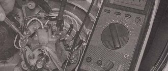
How to set the ignition?
When setting up the ignition, problems often arise with setting the signal advance angle. A voltmeter will help fix this problem. Looking ahead, it should be said that a device designed for a minimum of 15 V and 10-50 kOhm (internal resistance) is ideal. A voltmeter is connected directly to the terminals. Next, you should bring the piston to the position at which sparking occurs. Then turn on the ignition and turn the modulator until the readings on the device change. You can track the charge on the spark plug by the voltage on the sensor, which should jump. This value is equal to tenths of a volt close to the on-board power supply of the equipment. As soon as the spark is “groped”, you need to fix the position of the modulator directly on the generator shaft. This is usually done with a bolted connection. When adjusting the ignition, constantly short-circuit the high-voltage wires to the frame of the unit. Otherwise, excessive load on the ignition cannot be avoided, which can lead to its failure.