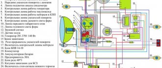
Domestic IZH motorcycles have been in stable demand for many years. Their popularity is due to a variety of reasons. For example, the cost of such a vehicle remains quite affordable. In addition, this equipment stands out from other motorcycles due to its exceptionally high-quality electrical wiring. In addition, Jupiter 5 is repairable and accepts various improvements with gratitude.
For example, you can easily switch to a contactless ignition system or install a new, more powerful generator. All you need is a detailed wiring diagram. If you know exactly the location of the main electrical connections, installing a new lock or connecting a diode headlight will not create any difficulties.
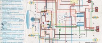
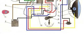
In this article you will find a color wiring diagram of the IZH Jupiter 5 motorcycle wiring diagram with explanations.
Detailed wiring diagram for IZH "Jupiter 5"
Before starting work related to connecting various electrical wiring elements, we recommend that you carefully study the wiring diagram of the IZH “Jupiter 5”. Fortunately, in this case, the wiring diagram and devices (generator, ignition switch, sensors, spark plugs, coils, etc.) are available in color and with all technical comments.
Please note that the standard Jupiter 5 electrical wiring rarely needs to be completely replaced. It was originally designed to work in domestic climatic conditions. Therefore, tampering with the electrical circuit usually involves connecting various elements. For example, with the transition to a contactless ignition system.
Light sources are also often replaced. The standard equipment includes incandescent lamps, which are much inferior to modern diode options. This is especially true for the headlight. This part changes frequently. And it is obvious that in order to correctly connect a new element, you need to know exactly the color of the wires and the general connection diagram.
Electrical equipment IZH Planet 5
The motorcycle uses 12-volt electrical equipment. The electrical wiring of the IZH Planet 5 motorcycle is single-wire, the role of the negative wire is performed by a metal frame.
Among the main components are:
- Power supplies;
- Ignition system;
- Headlight;
- Side lighting and turns.
The wiring for IZH Planet 5 is borrowed from other models of the manufacturer
For reference: as is customary in auto and motorcycle construction, modification of components and assemblies allows you to reduce the cost of products. For consumers, the advantage is that the price is low and a number of parts are interchangeable.
Generator
The motorcycle is equipped with a three-phase alternating current generator with an electromagnetic excitation circuit.
The principle of its operation is as follows:
- Electric current from the windings located on the stator is supplied to the rectifier;
- It converts it to direct current;
- And supplies it to consumers through the ignition switch.
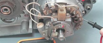
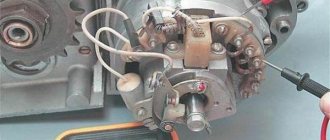
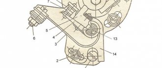
Factory instructions: design of the IZH Planet 5 generator
The instructions provided include the following items:
- Voltage regulator with rectifier BPV-14-10;
- Generator rotor;
- Generator stator with windings;
- Current collector brushes;
- Ignition system cam (battery);
- Ignition system contact unit
For reference: on three-phase generators of the IZH Planet 5 motorcycle, the windings are connected according to a “star” or “delta” circuit. The rectifier is installed as a separate unit, and the IZH Planet 5 electrical wiring is connected to it.
Headlight
Unlike European countries, where there is a requirement that motorcycles with permanent magnet generators must be equipped with a battery - since a motorcycle with a non-working engine must have side lights - there are no such restrictions in Russia (see also about the Ural motorcycle wiring diagram).
For reference: with such a generator, IZH Planet 5 did not need an external current source when starting the engine. Therefore, the battery was not included in the electrical equipment.
Headlight bulb replacement process
The head light circuit includes:
- headlight lamp (35W);
- blue indicator lamp (2W);
- headlight parking light (4W);
- rear brake light lamp (15W).
Control devices
The following control devices are installed on the motorcycle:
- speedometer with daily and total mileage counters;
- tachometer with indicator lamps for direction indicators and headlights;
- engine temperature indicator;
- voltmeter.
Standard set of control devices
Reasons for switching to a contactless ignition switch
Contact ignition, which is a standard part of electrical wiring, has several very significant disadvantages:
- inability to maintain angle advance settings for a long time;
- the presence of failures in operation, which greatly complicate start-up;
- minimal accuracy of spark formation at start.
It is clear that in this case you have to start the equipment many times before the engine finally starts. This has a negative impact on the generator, the lock, and the ignition system as a whole (one of the rare shortcomings of the Jupiter 5 electrical circuit). BSZ is completely devoid of all the above-mentioned disadvantages, moreover, it is easy to integrate into the connection diagram, practically without changing it. The transition to contactless ignition allows you to:
- increase power;
- reduce fuel consumption;
- align the torque and power curve.
Obviously, you can only make the transition to a contactless ignition system if you fully understand electrical wiring. Our diagram will accurately indicate the connection locations of all wiring.
Electronic ignition IZH – Jupiter
Fifteen years ago, the author of this article was an avid motorcyclist. I traveled a lot and experimented a lot with my iron horse. Therefore, I want to share my developments in the field of electronic ignition for motorcycles. And the reason for writing this article was the fact that IZH, having practically ceased to exist as a motorcycle, moved to another league. Now, based on units from IZH, homemade designers are building “cuttlefish” (pneumatic propellers) which are actively used by fishermen.
The desire to reconstruct my motorcycle arose in the early 90s of the last century. The goal is to get rid of the battery that was in short supply at that time. A generator and switch from Minsk, Voskhod were taken as a prototype. I won’t write how to install the Voshodov generator on an IZH, there is a lot of different information on this topic. We will talk about how to remake electronics for Jupiter.
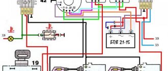
Below is a schematic diagram of the CET and winding data of the generator.
Winding data of the generator 43.3701 (Voskhod) 12 V, 65 W.
| Windings | Terminals | Wire brand | Wire diameter | Coils | Number of coils |
| Ignition | Z - M | PETV | 0,12 | 1800 | 2 |
| Nutrition | O2-M | PETV or PEV-2 | 0,9 | 67 | 6 |
| Sensor | D - D | —- ,,,—- | 0,16 | 1000 | 1 |
The conclusion immediately arises that Jupiter needs two ignition switches, i.e. two KET units. In this case, one of them is used both as a voltage regulator and as an ignition switch, while the other uses only the ignition system. In principle, you can stop there, but if you approach this issue creatively, you can squeeze the maximum possible out of the equipment. Therefore, it was decided to use the KET as a voltage regulator, and assemble the two-channel ignition switch into a separate unit.
During the experiments, it turned out that the standard generator winding and voltage booster circuit can deliver twice the voltage to the storage capacitor, namely, 360-380 volts versus 150 volts in the standard version. Why is this necessary? The increased voltage on the secondary winding of the ignition coil allows you to increase the spark gap on the spark plugs. Which in turn has a beneficial effect on the starting performance of the engine, especially at low temperatures. As a result, the switch circuit took the form shown in the figure.
The decrease in the capacity of storage capacitors is compensated by connecting diodes in parallel with the thyristors. On Internet forums there is often a question about the need for these diodes. To somehow clarify the situation, below I will provide a scan of a page from the book (I.M. Oparin, Yu.A. Kupeev, E.A. Belov “Electronic ignition systems” page 166).
Schemes and oscillograms of the discharge of a storage capacitor to the primary winding of the ignition coil: a - with partial transfer of energy to the ignition coil; b and c - with full energy transfer to the ignition coil
The curves for changes in capacitor voltage and current in the primary winding of the ignition coil are shown in Fig. A.
In Fig. b and c are diagrams in which the energy of the capacitor is completely transferred to the primary winding of the ignition coil, and curves of changes in the capacitor voltage and current in the primary winding of the ignition coil.
When the diode VD1 (Fig. b) is turned on in parallel with the thyristor VD2, the capacitor current is transferred to the coil completely, changing according to the law of damped oscillations, with the duration of the thyristor control signal exceeding the duration of the spark discharge.
In the circuit shown in “c”, the diode VD1 is connected in parallel with the primary winding of the ignition coil, which makes it possible to almost completely realize the energy stored in the capacitor. In this case, the duration of energy transfer (0 -t2) does not depend on the time of application of the control signal to the thyristor.
The main advantage of circuits with full energy transfer is the longer duration and energy of the inductive phase of the spark discharge than that of circuits with partial energy transfer.
The second option was chosen for the following reasons:
- The duration of the pulses from the ignition sensor is enough to maintain several periods of oscillation at low speeds with a gradual decrease to one as the crankshaft speed increases. (Checked with an oscilloscope.)
- At the end of the last half-cycle of sparking, part of the energy stored in the short circuit is given back to the storage capacitor. Therefore, the charging process does not start from scratch as in options A and B, but from some residual voltage, saving time and energy.
When operating KU 202N thyristors, breakdowns often occurred along the control electrode. This problem was eliminated by changing the thyristor control circuits.
To improve starting qualities, the ignition winding of the generator should be wound until the free space is filled, and impregnated with electrical insulating varnish. (The Z-M winding is made on plastic frames, which, as a rule, are not completely filled.)
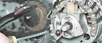
Next, you need to modify the generator, as shown in the figure. Exactly opposite the installation location of the standard sensor, cut a rectangular window, drill holes and tap threads to install the second ignition sensor. The mounting holes on the body of the second sensor should be slightly reamed to allow precise adjustment of the ignition timing. The work requires precision and accuracy. The ignition timing is set in the usual way, with the only difference being that for the second cylinder the timing is adjusted by moving an additional sensor, and not by rotating the generator housing.
In conclusion, a few words about installation. If you use capacitors of the K73-17 type, then they need to be glued to the board or the entire block must be filled with compound. Otherwise, they will simply fall off over time due to vibration. Ignition coils can be used standard from IZH, but it is better to take B 115 (excluding additional resistance) or B 117.
Author: Alexey Bazuev Tchaikovsky.
List of radioelements
| Designation | Type | Denomination | Quantity | Note | Shop | My notepad |
| Thyristor & Triac | KU202N | 2 | Search in the Otron store | To notepad | ||
| Diode | KD105B | 5 | Can be with the letters B or G | Search in the Otron store | To notepad | |
| Zener diode | KS680A | 2 | Search in the Otron store | To notepad | ||
| Zener diode | D814A | 2 | Search in the Otron store | To notepad | ||
| Resistor | 100 Ohm | 1 | 2 W | Search in the Otron store | To notepad | |
| Resistor | 1 kOhm | 2 | 0.5 W | Search in the Otron store | To notepad | |
| Capacitor | 1 µF 250V | 1 | Search in the Otron store | To notepad | ||
| Capacitor | 1 µF 400V | 2 | Search in the Otron store | To notepad | ||
| Add all | ||||||
Reasons for connecting a “foreign” generator and electrical diagram
The “native” generator, originally included in the design of the IZH “Jupiter 5”, is the second serious drawback of the motorcycle. It is weak, which makes it almost impossible to drive for a long time with the lights on. The battery runs out and the vehicle loses its performance. Moreover, the problem lies not only in the generator itself, but also in the fact that the possibility of connecting additional equipment is completely excluded. Therefore, you will need a wiring diagram to replace the standard device with a more “Chinese” one.
You can choose the appropriate option either independently or with the help of specialists. If you have little understanding of the electrical circuit of a motorcycle, it is better to entrust repair and improvement work to professionals. Specialists will correctly connect all the wiring and ensure the correct operation of the contactless ignition, lock, headlights and other elements.
