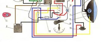
Installing a contactless ignition system on Izh Jupiter-5 is a fairly current topic. When setting up a BSZ on Izh Jupiter-5 BSZ, it is necessary to take into account a number of nuances that can significantly affect the operation of the equipment used.
What advantages open up to users who decide to install electronic ignition on the Izh Jupiter are described below.
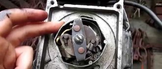
Most modern motorcycles are not equipped with cams, that is, breakers. Why did the manufacturer consider them unnecessary for currently sold models? The answer is quite simple. This system is not very reliable.
Many parts used in the system are sources of trouble. The most common ones are listed below:
- The ignition gaps change their original position while driving a few days after adjustment;
- A spark occurs every once in a while, since the contacts regularly burn out;
- Capacitors are constantly damaged;
- Low spark power;
- If you add two or three volts to the battery, it is quite difficult to start it. Such ignition is the reason for constant repairs while driving.
Many people mistakenly believe that it is very difficult to implement BSZ Sovek on Izh Jupiter 5. As a rule, it takes more time to purchase the necessary spare parts than to install the BSZ on Izh. Of course, after implantation, performance changes significantly in the best direction.
This is noticeable at idle. The speed of their passage has noticeably increased and the unnatural twitching has disappeared. The characteristic knocking sounds of iron components in the crankcase and accompanying detonations also disappeared. The handling of the Jupiter 5 motorcycle will improve simultaneously with the time it takes to gain speed.
Required Parts
In order for the ignition system to work correctly, a number of auxiliary parts are required. They are listed below:
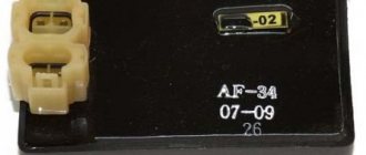
- Switch for BSZ VAZ cars. You should not choose exclusively from the low price segment. The Astro switch has a lot of positive reviews;
- Hall Sensor. The best option for Jupiter 5 is a similar manufacturer VAZ. By purchasing it in branded packaging, you protect yourself from counterfeits;
- Ignition coil with two terminals. You should choose between the gazelle engine number 406 or Oka with an electronic ignition system;
- A pair of silicone armor wires with rubber caps;
- The modulator is a butterfly-shaped plate made of iron.
Modulator
The most difficult stage is the production of the modulator. It is important to maintain the required shape. The more accurately the required dimensions are observed, the lower the likelihood of problems occurring after the system is implemented, that is, there will be no need to adjust it with a file. The ignition timing must match on any cylinder used.
The bolt hole must be located in the middle. Otherwise, the engine operation will not be synchronized. It is also recommended to check the integrity of the crankshaft bearings. If you find defects, you should immediately replace it.
The contact ignition is not able to work normally if the bearings are damaged. The thickness of the part should not exceed one and a half millimeters. If it is thin, it will not be possible to avoid deformation, and if it is thick, it will come into contact with the surface of the hall sensor housing.
To create the plate, it is allowed to use any material except steel. Aluminum and others should not be used as they are not magnetic. The drawing that must be followed can be found in the public domain. The presented diagram will be useful to those people who decide to modernize the vehicle ignition device. Below are methods for installing electrical ignition devices in Jupiter.
It must be turned by a professional turner. He will make a simple disk and draw on it the markings of elementary distances between the corners. Then, in accordance with it, you will cut out the necessary sectors at home. The cost of the modulator is seventy rubles.
It is not advisable to use an ordinary plate, since its width is less than twelve millimeters. This will not be enough to fully accumulate the energy resource in the coil. Of course, it can be installed, but achieving four thousand revolutions per minute will become impossible.
In addition to the above you will need:
- A stud with an applied thread of seven millimeters, pitch 1, as well as a pair of nuts with washers of the corresponding parameters. The priority material for these components is brass. This is explained by the least magnetization of the plate from the generator rotor.
If you use a standard bolt, then difficulties may arise with the implementation of the ignition. The bolt tends to follow the modulator as it is tightened. However, it is necessary to observe the leading indicator, maintain the same position of the rotor and modulator, and tighten the bolt. It is advisable to use a pin, since many are not able to perform all the necessary actions in total;
- A set of wires with connectors for ignition without contact from VAZ. This part can be purchased or made with your own hands.
Replacing the connecting rod bushing IZH Planet 5
The cylinder-piston group can be disassembled without removing the engine from the motorcycle. This, as a rule, has to be done to clean the piston and combustion chamber from carbon deposits, as well as to replace worn parts.
1. Remove the fuel tank.
2. Unscrew the exhaust pipe nuts and move the pipes away from the cylinder.
3. Remove the carburetor.
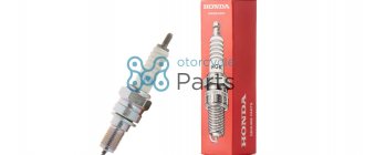
4. Remove the tip of the high voltage wire from the spark plug, remove the ignition coil, and unscrew the spark plug.
5. Disconnect the decompressor cable and unscrew the valve.
14 mm socket wrench
Unscrew the six nuts securing the cylinder head in a criss-cross pattern.
7. Remove the head.
14 mm spanner
unscrew the four nuts securing the cylinder to the crankcase.
9. Remove the nuts with spring washers.
10. Lower the piston to bottom dead center by rotating the motorcycle wheel or pressing directly on the piston. Remove the cylinder.
11. Cover the opening of the crank chamber with a clean rag to prevent foreign objects from getting into it.
12. Turn the cylinder over, install it on the studs and, carefully prying it with a knife, remove the gasket from the cylinder.
13. Similarly, remove the carburetor gasket (if it was not removed along with the carburetor).
14. Inspect the cylinder mirror. No scuffs, signs of heavy wear, grooves, enveloping of aluminum from the piston and other damage are allowed on it. This cylinder must be repaired or replaced.
You cannot grind the cylinder mirror with sandpaper and then polish it. The only possible processing is boring on a lathe to the repair size with mandatory subsequent honing. In this case, it is necessary to install a piston and rings of repair sizes (see below).
15. Using a scraper or knife, clean the cylinder exhaust windows from carbon deposits. Before this, carbon deposits can be softened with kerosene or acetone.
16. Check the condition of the threads in the spark plug hole. If the thread is damaged by more than a third in height, replace the cylinder head.
17. Similarly, inspect the thread of the hole for the decompressor.
If necessary, the cylinder head can be repaired by installing a liner in it. To do this, drill the spark plug hole to a diameter of 18.4 mm and cut an M20x1.5 thread in it. We grind a futor from brass or bronze (see figure) and, wrapping it into the hole, counter flare the lower edge. Such footwear is also available for sale.
Spark plug hole
18. Inspect the sealing band of the cylinder head. If unevenness is noticeable on the belt, grind the belt on a bench plate (with paste for grinding valves) or with an even, small abrasive stone.
19. Using fine sandpaper, clean the surface of the combustion chamber from carbon deposits.
20. It is useful to polish the combustion chamber with the finest sandpaper (with water), and then with GOI paste to a mirror shine. This way there will be less carbon deposits on it.
21. If the piston rings are to be replaced, they can be removed by breaking them. Otherwise, carefully place strips cut from a plastic bottle under the rings and remove the rings from the piston.
When using the old rings later, we mark them so that they can be installed in their original places during reassembly.
22. Using snap ring pliers or round nose pliers, squeeze and remove the piston pin snap rings from the piston. Do not compress the rings excessively to avoid permanent deformation.
23. Using a hammer, knock out the piston pin through a suitable mandrel (it’s easier to do this with two people).
24. Remove the piston.
25. We clean the piston bottom and ring grooves from carbon deposits (you can use a piece of an old ring). It is recommended to first soak the piston in acetone. It is also recommended to sand with fine sandpaper (with water) and polish the piston bottom (including a new one) with GOI paste, so less carbon deposits will be deposited on it.
System assembly and installation
The contacts in the breaker, the capacitor, the ignition bobbins and the armor wires, which are part of the previous ignition device, are probably eliminated. The switch should be installed in the glove compartment on the right, and the ignition coil directly under the tank. There are no gaps for fastening on the reel, which means it can be attached using a thick layer of adhesive tape. The standard bolt is also eliminated along with other parts.
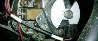
In place of the bolt, install a pin of the specified size and put on a washer. Then, the rotor is tightened with a nut located at its end. The hall sensor is attached to the stator by any means. The basic rule when installing it is to set the optimal cross-sectional distance of the modulator and the ratio of the radius and line of symmetry.
Final actions
You should put rubber caps on the armor wires, and insert the latter into the candlesticks or coil above. If you skip this step, the motorcycle will stall when riding in rainy weather, as moisture will get into the battery.
By inserting spark plugs into the tip, it will be possible to maintain excellent contact between the battery and the volume of the vehicle. Now you will need a pre-purchased set of wires. The switch, coil and hall sensor are connected by wiring. She needs to be isolated. Of the entire mass, only a common plus is required.
Setting the appropriate options
Setting up the BSZ on Izh Jupiter 5 also requires special attention. The ignition is turned on with the tachometer connected. After thirty seconds, indicators of 3000, 4000, 5000 rpm should appear on the device panel. If they are present, then the switch is working correctly.
In other cases, you should pay attention to previously grounded candles. We insert a screwdriver into the hall connector and then pull it out. A spark should appear on the spark plugs. If it was not possible to cause a spark using the steps described above, then the reason for the incorrect operation is incorrect connections.
The setup looks like this. The dial indicator is unscrewed and the cylinder piston is adjusted. Having connected the voltmeter to the second and third connectors, you need to start rotating the modulator axis. After a jump from 7 to 0.1 volts is detected, the modulator must be secured with a nut. Usually the required advance angle is set.
The test run should be successful if you install the components yourself according to the instructions. Now you can use BSZ.
The main problem with the Izh Jupiter motorcycle engine is the standard contact ignition system. Any owner of Jupiter sooner or later faces the problem of failure of one of the cylinders due to a change in the gap in the contacts or failure of the capacitor. Adjustment helps, but usually not for long. This problem can be radically solved by installing a contactless ignition system on a motorcycle.
Single-channel BSZ.
There are probably many options for BSZ design, but we won’t consider them all. Let's focus on the simplest, and probably the most common option in our country. There is no motorcycle market or motorcycle store nearby where you can buy a factory-made BSZ, and there is no turner with a machine nearby either. We will proceed from this.
Minimum set for installation
But we can’t do without a minimum set, so before you start work, you need to stock up on the following components, which are sold in any auto shop or car market in our country:
1. Switch from VAZ 2108
2. Hall sensor from VAZ 2108
3. Set of wires for BSZ from VAZ 2107 (from distributor (Hall sensor) to switch)
4. Two-terminal ignition coil (from an Oka or Gazelle car with a ZMZ 406 engine)
5. Two automotive silicone high-voltage wires of the required length with caps for spark plugs (you can buy a kit for a VAZ and take it from there, you can simply find used wires, after first making sure they are working)
Next, in addition to the components, we will need a small flat piece of sheet steel 1-1.2 mm thick to make a modulator and a plate for the Hall sensor. I warn you right away that stainless steel or non-ferrous metals are not suitable for the manufacture of the modulator, since they are not magnetic materials. To make a plate for the Hall sensor, you can use any material of sufficient strength.
Tools you may need are a drill with drills, files, a chisel, a hammer and other tools that, as a rule, are found in any garage.
Rework process
We dismantle the old ignition system. We remove the plate with contacts, capacitors, ignition coils with high-voltage wires from the motorcycle. We install the switch in the right glove compartment.
We attach the ignition coil to the frame under the tank. We connect the wiring connector to the switch, connect the black ground wire from the connector to ground. We connect the wire from terminal No. 1 of the switch connector to one of the coil terminals. We connect the second terminal of the coil to the old wiring, to the wire to which “+12V” is supplied when the ignition is turned on. In the old wiring, this wire connected both ignition coils. From it we pull an additional “+12V” wire to the switch, which we connect to the 4th wire in the connector. We carefully isolate everything. We insert the wire with the connector to the Hall sensor into the cavity of the generator.
You can check the functionality of the system. We connect the Hall sensor to its connector, connect the high-voltage wires to the coil and to the spark plugs. We provide reliable weight to the candles. Turn on the ignition and pass a metal object (you can use a flat screwdriver) through the Hall sensor slot. The spark plugs should spark. The scheme is working. (If there is no spark, then something is connected incorrectly and everything needs to be checked again.) Now it remains to supply a spark at the right time to the cylinders, for this:
All. Optical ignition installed.
You can ride and enjoy a stable spark.
What is a stable spark? This includes even idle speed, traction under load, and finally, a beautiful, clear engine sound, and the delicious smell of burnt fuel and oil.
This is roughly how Tula drives through the snow. You can read it here, they did a special test.
In general, if you have some domestic motorcycle gathering dust in your garage, if you console yourself with the dream of restoring it, you cannot live without optical ignition.
We must take it and put it on!
Did you like the post? Share with your friends! =)
