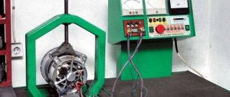
The difference between Kat and Bks. Generator device.
Kat is an electronic device intended only for switching and generation at a certain moment, according to a signal from a high-voltage pulse sensor to produce a spark. used (used) in batteryless motorcycles with a 6 volt (mostly) lighting system. Bks is a two-in-one device. The BCS consists of a Kat and a 12-volt voltage stabilizer (for lighting). It restrains excess voltage so that the light bulbs do not burn out, but sometimes it acts up and at high speeds it holds back too much and this makes the light worse at speed. The generator consists of 2 (in older models, out of 3, the third was used for turn signals) separate electrical systems independent of each other. 1. ignition system. two coils of approximately 600 ohms (produce about 150 volts for charging the capacitor in the BCS or KET). The same on all batteryless motorcycles (mopeds) 2. lighting system. 3 reels and 3 reels. connected in parallel to increase the current. with a different number of turns depending on whether the system is 6 or 12 volts. The power in watts is determined by the thickness of the wire wound around these coils.
7 comments were left on this post.
Have you decided to tell everyone? This is right, otherwise it’s a sore subject for many
Gennady Aniskin, thanks for the explanations! Excuse me, but is that Aniskin who caught Fantômas your relative?
No pinning of course. namesake
Gennady, Can I add this text to our group?
I was told that there is not much difference between cat and bks, so can I put cat on 12v gen?
Danil, you can. (uses for ignition)
Just wondering what needs to be done with the BKS so that the light glows well at speed, otherwise the light dims
Contactless ignition on Izh Jupiter 5.
If you are the owner of a more modern and beloved BSZ motorcycle on Izh Jupiter 5, then in addition to all its well-known advantages, ease of customization will also be added. To begin with, we need to unscrew the spark plugs and, without removing them from the spark plug caps, lean them against the ribs of the cylinder, then catch the T.M.T. one of the pistons and rotating the crankshaft back lower the piston by 2.6 mm. When the advance is set, we move on to the modulator.
This element must rotate freely, due to which we must “catch” the moment of spark formation (on the spark plug) with the ignition on. Next, you need to very accurately fix the resulting position by pulling the modulator. Now let's move on to the next cylinder. We also place its piston in the top position, and then unscrew it, lowering it by 2.6 mm. Now, turning the crankshaft by the generator nut, we look at the ignition. If it matches, then everything is set, if there are deviations, then we proceed as follows: for early spark formation, loosen the lock nut of the modulator and set the ignition in the manner described above, then move on to the option when the ignition is later.
With late ignition, the edge of the modulator grinds down until, with the advance set, a spark is formed at the right moment. Finally, leaving the spark plugs on the cylinders, we crank the engine using the kickstarter, determining the evenness of the spark plug formation “by eye.” You can more accurately monitor the accuracy of the settings only by running the engine.
What is a cat on a motorcycle?
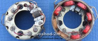
Switches KET-1A, BKS 251.3734, BKS 261.3734, BKS 1MK211, BKS 70.3734, BKS 94.3434 are designed to work with generators 26.3701 (6V 45W), G-427 (6V 65W), 43.3701 (12V 65W), 80. 3701 (12V 90W), GM-02.02, GM-03.02, R71, 92.3702M-02.02, GM-03.02, R71, 92.3702.
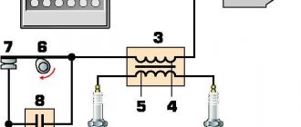
Switch circuit KET-1A.
The scheme works as follows.
The alternating voltage of the generator from the ignition winding L1 is supplied to the rectifier diode V1. The rectified voltage through the R6 V5 chain and the ignition coil charges the battery of capacitors C2 C3. Some time after charging the capacitor, is received from the generator sensor L2 to the control electrode of thyristor V6. Thyristor V6 will close the battery of capacitors C2 C3, which will cause a sharp change in induction in the ignition coil and sparking at the electrodes of the spark plug (the voltage on the secondary ignition winding reaches several tens of kilovolts ). Current limiting resistor R6 and smoothing capacitor C1 are used to limit the current of the ignition winding L1 and smoother charging of the bank of capacitors C2 C3. Zener diodes V3 V4 provide voltage stabilization at a level of 150 V. Voltage stabilization is necessary so that the battery of capacitors C2 C3 and thyristor V6 do not fail due to overvoltage. Chain V2 R2 is necessary for rectifying and matching the signal from sensor L2 with the control electrode of thyristor V6. This switch has a number of disadvantages and weaknesses :
- The maximum operating voltage of capacitors C2 C3 is 160 V, and since the voltage is stabilized by zener diodes V2 V4 at 150 V, the capacitors operate at the limit of their capabilities. Zener diodes of the D817 series have an error of 10%, so the risk of failure of capacitors C2 C3 is quite high.
- When the switch operates for a long time, resistance R6 becomes very hot. As a result, the soldering may melt or the resistor itself may burn out.
- The circuit between the generator sensor and the control electrode of thyristor V6 does not contain a filter against interference and interference, as well as overvoltage protection (stabilizer). The result is unstable operation and the possibility of failure of the V6 thyristor at high speeds.
- At high engine speeds, capacitor C2 C3 will not have time to charge - resistor R6 will limit the charging current of the capacitors .
The diagram of switches BKS 251.3734, BKS 261.3734 is shown in the figure.
All BKS switches contain two circuits: ignition and lighting. ignition circuit is similar to the KET-1A switch, and therefore has the same disadvantages . True, in switches of later releases (starting from the late 80s), the capacitance C1 is 2.2 μF 250 V (as in 2MK211). Let's consider the principle of operation of the lighting stabilizer . From the lighting winding of the generator L3, alternating voltage is directly supplied to contact 02 of the switch output (according to the diagram on the right). Thyristor V5 is closed. At the moment when the voltage of winding L3 exceeds the specified value ( 14 V or 7 V ), thyristor V5 opens and closes winding L3 to ground. This will happen only with a positive half-cycle (relative to ground) at terminal 02. The thyristor control circuit works as follows: the alternating voltage is rectified by the diode bridge V9 and supplied to the voltage divider R2 R3 R4. The ratio of R2 and R3+R4 determines the division coefficient. Smoothing capacitor C3 ensures stable operation of the circuit. When the voltage in section R2 R3 exceeds a certain value, the zener diode will open, supplying voltage to the control electrode of the thyristor . For a 12 V lighting circuit, zener diode V7 D814A (opening threshold 7.7 V), and for 6 V, respectively KS147A (opening threshold 4.7 V). The zener diodes are selected in such a way that the voltage at the control electrode does not exceed 3 volts , otherwise the thyristor will quickly fail. Therefore, when converting the switch to a different voltage, it is necessary to replace the zener diode. By selecting resistor R3, the voltage at the output of the switch adjusted The advantage of the circuit is that the voltage from winding L3 does not decrease when thyristor V5 is closed, since it is connected in parallel with the lighting winding. This is important when the engine is idling .
The BKS94.3734 switch is designed to work with generators GM-02.02, GM-03.02, R71, 92.3702 . The main feature of the switch is the absence of sparking when the generator is reversed . Chain V2 R5 VT1 shunts the signal from sensor L2 when the rotor rotates in the opposite direction and in the presence of a false signal ( the sensors are located inside the generator ).
Block BKS 70.3734 is the predecessor of the Kovrov 2MK211. The blocks are designed for generators with an internal sensor and are practically the same. Below are diagrams of the BKS 1MK211 and BKS 70.3734 switches.
The design of BKS 70.3734 block as well as the topology of the printed circuit board .
The ignition circuit is slightly different from KET-1A. The above shortcomings have been eliminated . The sensor circuit contains a rectifier V6, a filter R1 C4 C5, and a voltage stabilizer R1 V3. Such a switch is more resistant to interference and interference in the sensor circuit. However, it is not suitable for forced engines . The lighting circuit of the switch is similar to BKS 261.3734.
Let's start tuning a Minsk motorcycle with our own hands
To increase power we will tune the engine, clutch, ignition system, cooling and exhaust.
Engine tuning in Minsk - adding a few horses
The most powerful engine in the base, as mentioned above, is a maximum of 13 horses. Of course, this is completely insufficient for modern dynamic riding, motocross, and stunt riding (depending on what the motorcycle tuning is for). Modifying the Minsk engine is not very difficult. To increase power, you will have to work on the cylinder and piston of the motorcycle engine. We reduce the combustion chamber by grinding. This increases the compression ratio and engine power. The engine is now suitable for using high-octane gasoline and this will have a positive effect on increasing power.
Read more: Voltage on a new car battery
Motorcycle engine Minsk
So let's get started:
- It is necessary to change the overall dimensions of the inlet, bypass and exhaust holes in the cylinder to improve the filling of the gas-air mixture and more dynamic release of burnt gases.
- You can replace your original pistons with Japanese ones with improved performance.
- A reed valve must be installed at the inlet of the cylinder itself.
Tuning Minsk for sports
Such tuning of the engine of this motorcycle will allow you to add several horsepower to the power, which will immediately noticeably affect the dynamics and acceleration speed. The increased power as a result of engine modification will require replacing the standard crankshaft bearings with more durable ones. For this, it is best to use imported bearings produced by the Japanese company NTM.
Photos of tuning the Minsk 125 motorcycleReworking the ignition system
The standard ignition system with a very powerful and reliable generator, a contactless ignition system and an electronic switch require modification in terms of additional installation of a device to change the degree of ignition angle advance depending on the engine speed. With the help of such tuning, the Minsk motorcycle engine will run more smoothly and quietly, and its service life will increase significantly.
Motorcycle tuning Minsk
Exhaust tuning for a Minsk motorcycle
How to make a Minsk motorcycle quieter? To improve the power performance of this engine, it is very important to install a resonator in the exhaust system. A resonator is an oscillatory system where vibration energy is accumulated due to resonance with the driving force
A properly selected resonator allows you to ensure that some of the lost working mixture is returned to the cylinder by the time the exhaust window is closed. It is very difficult to find such a device for free sale, because... it was produced in limited quantities and only for cross-country versions of the Minsk motorcycle. But you can make it yourself using drawings available on the Internet.
Tuning the exhaust system on a motorcycle Minsk
Motorcycle tuning Minsk
Cooling system tuning
Increased power as a result of engine tuning will require a more efficient cooling system. It is necessary to purchase and install a more serious radiator.
Clutch modification in Minsk
Now, after engine tuning, the standard clutch will not be able to cope with the increased power in all operating modes of the motorcycle engine. It needs to be improved by replacing springs and discs. It is necessary to cut off a few millimeters of steel from the standard clutch discs and insert three more selected discs into the free space. As a result of this replacement, the clutch will become slightly stiffer in first gear, but overall the motorcycle will gain more dynamics and drive.
Now we can replace the rear wheel sprocket with a similar one, but with fewer teeth, which will add dynamics to the acceleration of the motorcycle. We replace the standard brakes with good disc brakes - do not forget about driving safety. All these measures, if carried out correctly and responsibly, will allow you to increase the power of a 125 cc motorcycle engine from the standard 13 to 20-23 horsepower, which of course will make your iron horse much faster and more interesting. A technically savvy owner can do the tuning of a Minsk motorcycle engine on his own, or you can contact a motorcycle center, where all the necessary work will be carried out not only quickly and efficiently, but also where you can quickly purchase all the parts and elements necessary for tuning a motorcycle.
Electronic ignition switch KET - 1A
Recently, a switch on my motorcycle, such as KET-1A, stopped working. This switch is used in old Minsk and Voskhod motorcycles. It relates only to the ignition and has nothing to do with the rest of the motorcycle electronics.
In general, switches of this type are not highly reliable, for this reason I have already accumulated about a dozen of these devices. Among the breakdowns in the switch there are different ones, diodes, zener diodes, thyristors, and capacitors can burn out. These are the very first places to search. Resistors rarely burn out. Contacts can often be unsoldered. I had different breakdowns in each of the switches, but most often, due to a non-sealed case, the board tracks or leads of some components were oxidized. When the next switch failed, I decided not to buy a new one, but to assemble it from the parts I had from old similar devices.
After searching the Internet a little, I found a diagram and redrew it in Splan.
I also drew the board in Sprint Layout 5.0:
Explanations for the markings: K – cathode of thyristor KU201 U – controlled electrode of thyristor KU201 A – anode of thyristor KU202 K2 – cathode of diode D4
The finished printed circuit board must be coated with a protective varnish to prevent oxidation of the tracks.
Necessary components: - 2 zener diodes D817V - thyristor KU201V - 3 diodes KD105V - 2 capacitors 1uF 160V - 1 capacitor 1uF 250V - resistor 1K - resistor 100
The device is assembled in a standard aluminum switch case. When installing the switch cover, it is necessary to coat all joint seams with sealants to prevent moisture from getting inside.
How to set the outline for the best ignition
Initially, the outline is installed at the factory, when the finished motorcycle is in a state of assembly, and is tightly adjusted with special screws. In most cases, this avoids problems, but sometimes they become loose, disrupting the course of the ignition spark and reducing its intensity.
Setting an outline on a Minsk motorcycle is not easy. This procedure takes a lot of time and effort, and also requires utmost attention from even the most experienced drivers. Therefore, you need to start it only if you are absolutely sure that the problem lies in the outline. You can check this by measuring the intensity of the spark when adjusting the contacts. Changing it indicates a problem, but if it remains stable, no adjustment is required.
Loosen the outline screws and check how the spark changes. If it increases with increasing distance between the contacts, then the plate should be gradually rotated clockwise, and vice versa if it decreases. The steps must be repeated until you get a strong ignition spark that will remain stable when the distance between the contacts changes.
Installing a Minsk motorcycle ignition will be much easier with the assistance of experienced drivers or mechanics if you are new to this matter. However, you can easily do it yourself, paying maximum attention and effort to it, saving a lot on the price of repairing a motorcycle at a service center.
- https://motoking.ru/sovety/kak_otregulirovat_zazhiganie_na_motocikle_ural
- https://avtorep.ru/nastrojka-zazhiganiya-na-motocikle-ural/
- https://real-biker.ru/articles/zazhiganie-minsk-principy-regulirovki-iskroobrazovaniya-dlya-dannoy-modeli-motocikla-28/
Generator Voskhod G-427
Generator G-427 alternating current with excitation from a permanent magnet with an inductive sensor of the electronic ignition system. In the grooves of the stator, made of stamped electrical steel plates, eight coils are placed, which form four independent circuits: - power supply to the ignition storage capacitor; — lighting and sound signal; — direction indicators; — braking signal.
Voltage regulation in the circuits of lighting loads is carried out according to the principle of parametric regulation, i.e. The winding data of the generator are selected in such a way that as the rotor speed increases, the voltage at the generator terminals changes within certain limits for a certain load. Attaching the generator stator to the engine crankcase provides adjustment of the ignition timing.
On the generator stator cover there are terminals: - charging coils of the power supply circuit of the Voskhod ignition storage capacitor; — direction indicators; — brake signal; — lighting; — sensor.
Which are marked accordingly: >, >, >, > and >.
The sensor is mounted on the generator stator cover using screws.
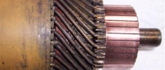
Generator rotor
The generator rotor with the sensor rotor located on it is mounted on the right axle axis of the engine crankshaft with a bolt and is secured against rotation by a key.
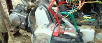
Scooter ignition
Ignition from a scooter on the Izh Jupiter can work without a battery. Before setting it up, we need three details:
- Scooter switch;
- Ignition coil;
- Inductive original sensor (must have a single wire output).
The DC switch is powered from a 12 W network, also the on-board network of the motorcycle is 12 W, the switch has 4 wires, the first of which is plus, the second is minus, the third is to the coil, the fourth is to the inductive sensor. We reliably connect the negative wire from the switch to the negative wire from the motorcycle (ground), and connect the positive wire that goes to the standard coil to the positive wire of the switch.
Ignition coil connection:
- We connect the negative wire to the ground of the motorcycle;
- we stretch the second wire to the switch and connect it to the output under the coil
In order not to pull an additional wire to the inductive sensor through the entire engine, you can use the wire that connected the contact group and the standard ignition coil.
To do this, you need to take the wire from the switch that goes to the inductive sensor and connect it to the wire that went to the standard coil. Next, remove the capacitor and connect the inductive sensor
Particular attention must be paid to positioning the generator cover. It needs to be installed properly and not touch anything when rotating.
To do this, you need to shorten the cam a little and also make notches on it that prevent the modulator itself from turning. It is also worth observing the parameters of the gap between the modulator and the inductive sensor, which should be within 1-1.5 mm. When installing the ignition, you need to know that the spark strikes when the modulator leaves the sensor, and not at the input.
Once electronic ignition from a scooter is installed on a motorcycle, its performance will improve significantly. In particular, it will start much better (this will be especially noticeable when the battery charge level is low). Speed gain will also improve noticeably. The motorcycle will idle smoothly, which indicates proper engine operation.
Caring for a sunrise motorcycle generator - how to remove, what to check and install correctly
Generator maintenance mainly comes down to tightening the threaded fasteners of the generator stator and rotor, as well as the wire terminals.
In order to remove the generator, you must:
- disconnect the wires of the ignition circuit, sensor, brake light and direction indicators from the generator terminals;
- unscrew the three screws securing the stator to the crankcase and remove the stator;
- Unscrew the bolt securing the generator rotor and, with light, careful blows of a wooden hammer on opposite sides of the rotor, remove it from the trunnion and remove the key.
Checking the removed parts
After removing the generator stator and rotor, wash the parts with clean gasoline and carefully inspect them. Disassemble the wire fastening terminals on the stator. Wipe dry all insulating parts of the terminals.
Generator installation
Installation is carried out in the reverse order, in this case it is necessary:
- check the runout of the generator rotor, which should be no more than 0.1 mm with the bolt secured;
- tighten the generator stator without distortions, ensuring a tight fit to all three supports;
- install the ignition correctly;
- The generator wires must be securely fastened and well insulated from each other.
Will we love “octams”? We choose motorcycles up to 125 cm³
Subcategory of rights A1, which includes motorcycles with a displacement of up to 125 cm³ and a power of up to 11 kW (14.9 hp), is a resolved issue for Russia. So, we have reached the level of civilized countries, but should we be happy or sad about this? Previously, the “one hundred and twenty-five” niche was not particularly popular in our country and there was little technology. What awaits the market in 2012?
000_moto_0312_036
All motorcycles imported into Russia can be roughly divided into two categories: . However, this division is very arbitrary: even well-known models are “yellowish,” if not entirely made in China, Taiwan, or even Turkey, Indonesia and Vietnam. It is significant that famous brands usually have one or two “125” class models in their lineup. After all, this equipment is, as a rule, a training desk, which cannot be bypassed by law. And there will always be a demand for it, until the craving for motorcycling fades or the last drop of gasoline is burned. Only companies with image bikes (such as Harley, Victory or Ducati) do not condescend to unpretentious “sufferers”. But there are progress here too, an example of this is KTM (we’ll talk about it separately).
IT'S NOW CHEAPER
The “under 50” group (we are talking about thousands of rubles) is opened by two twins: Lifan LF125–5 and Patron Simpler 125, clones of the Honda CG125 model of 1976. Their appearance is archaic. A very common engine in China with a characteristic lower camshaft (OHV design) is installed in an open steel frame. This shaft has only one cam, which, through two pairs of rocker arms and a rod, controls two valves in the head. The engine turned out to be compact, lightweight, reliable, there are no problems with spare parts or repairs. And the devices themselves are extremely simple: drum brakes, primitive spring suspensions, passenger footrests are attached to a pendulum made of a thin round pipe, which does not pretend to be rigid. Fans of the style of the late 1970s, and indeed old hardware in general, will appreciate the shape of the tank, stylish markings, 18-inch spoked wheels, fenders and seat base made of natural steel. There is a lot of chrome, a strong trunk, a tachometer and an electric starter. On the training “figure”, the motorcycles are simply super: light as a bicycle, the angle of rotation allows you to pass the figures with a margin, and neutral is easily caught. Brakes on the training ground are not particularly needed, it is even valuable when they are weak, so as not to accidentally block the wheel and trip. But on the road you feel uncomfortable with these, especially in the city.
A little further from the border of primitivism is the Patron Aero 125F. It is equipped with the same “tsegesh” four-stroke “air vent”, but with glimpses of modern design. There are cast five-spoke wheels, more advanced suspensions and a sporty-looking muffler a la Akrapovich. The view is no worse than that of its Yamaha classmate (we’ll get to that later), but the price of the Aero is almost half as much.
Not far from this technology are the Minskis, of which there is a whole range on our market. Actually, the “125” cubic capacity has become the crowning glory for Belarusian cars since 1951, when they began producing a copy of the German DKW RT125. The descendant with a two-stroke engine is today called Minsk M125. The motorcycle does not have a separate lubrication system and an electric starter (there is no battery either), with a four-speed gearbox. Spoke 18-inch wheels - with drum brakes (there may be a disc at the front, but you need to look for such equipment), a durable closed-type frame is used, a sealed chain casing, suspension - with “hydraulics”. Minsk M125X with the self-explanatory name “Forester” is equipped with a durable three-sided trunk, headlight protection combined with a small trunk and an “upper” plastic wing.
But the Minsk C4 125 with a 4T engine is priced out of our group, but it is logical to consider it along with the others. After all, in fact, it eliminates all the shortcomings of simple Minsks: it has an electric starter, a front disc drive and a five-speed transmission. True, I had to sacrifice the chain casing. Although Minsk is cast on the cover of the unit, it is produced by the famous Chinese company Zongshen. This is not a clone of a Honda engine, but a Yamaha one, in which the camshaft is located in the head (ONS diagram). This classic-looking device is very good for both beginners and rural residents, many of whom still have Soviet two-stroke bikes from Minsk in service.
PRETEND TO BE A MOPED?
Although devices in the guise of a classic scooter are popular in Europe and are even updated by such giants as Honda, Yamaha, Suzuki, they are not brought to us - they are not prestigious and expensive. And most importantly, the small demand is fully satisfied by the Chinese motorcycle industry: cheap and cheerful. Although you rarely see the “125” cubic capacity, these are usually engines of 90–110 cm³. Examples on our market are Irbis Irokez 125, Patron Ringer 110. Like all scooters, they are attracted by improved protection from wind and water, plus a semi-automatic transmission. That is, you still need to change gears, but you don’t have to think about the clutch and the possibility of stalling. What is especially valuable is that you can pass the traffic police exam on a scooter. In addition, these devices are extremely light, and large 17-inch wheels and a sufficient turning angle facilitate the passage of the “figurine”. And in city traffic you feel like a fish in water (the author knows this firsthand - he himself has covered 20 thousand km, mostly in the metropolis).
Ignition adjustment Voskhod
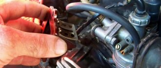
The ignition timing is set by turning the generator stator after first loosening the three screws securing the stator to the crankcase. For normal engine operation, it is necessary that the moment of spark formation (on the generator, this moment is determined by the coincidence of the sensor rotor groove with the protrusion on the sensor coil frame. Fig.) coincides with the moment when the piston does not reach the top dead center of 2.5-3.0 mm (at running the engine on gasoline with an octane rating of 92).
The gap between the rotor and the core of the sensor coil should be within 0.3±0.05mm.
The gap should be set as follows:
- loosen the screws securing the sensor stator to the generator stator cover;
- By moving the sensor stator in the grooves of the generator stator cover, set the required gap, and then tighten the fastening screws.
How to set the ignition on Jupiter | Do it yourself
Many motorcycle owners have had the opportunity to set the ignition on them themselves. It's not difficult to do this. However, you need to have an idea about the structure of the system itself. You will also need a special tool for the job.
Instructions
1. You need to get a 12 V lamp with two wires. You will also need a tester. You can use a caliper as a depth gauge. It is easier for everyone to measure the gap with the support of a feeler gauge.
2. First, unscrew the generator cover. You can also remove the entire right crankcase cover. This will make it much more comfortable to work further. Turn the crankshaft clockwise. Rotate using the generator bolt. It is your responsibility to achieve maximum opening of the breaker contacts. After this, loosen the screw and turn the eccentric. There should be a gap of 0.4 - 0.6 mm between the contacts. Tighten the screw thoroughly.
3. After this, rotate the crankshaft clockwise. The piston must be set to top dead center. After this, rotate the crankshaft counterclockwise. The piston should not reach TDC approximately 3.0 - 3.5 mm. Loosen the screws and install the contact opening preface. Tighten the screws carefully. It is easier for everyone to determine the opening of contacts using a probe. Connect one of its wires to ground, and the second to the breaker hammer terminal. Turn on the ignition. The lamp should light up when the contacts are opened.
4. If you have BS3, then you need to exclude the item for setting the gap. You will need to determine the moment using a tester. Set it to measure voltage. Connect it to the second and third contacts of the DC. The tester should show a voltage of about 7 volts when the modulator is not in the DC. When the modulator is in the DC, the voltage should change from 7 V to 0. At this moment, sparking occurs.
5. Set the ignition separately for each cylinder. It is recommended to start by adjusting the gap on the left breaker. After installing the ignition on it, you can move on to the right breaker.
Tip 2: How to set the ignition on a motorcycle
If your motorcycle does not start or operates abnormally, then the possible reason is that the ignition is set incorrectly
Special attention should be paid to this problem
Instructions
1. It’s worth noting right away that the generators “G-401”, “G-411”, “G-421” have a mechanical ignition system. To set the ignition, you need to positively adjust the gap between the ignition contacts. Please note that you will also have to adjust the outline at the same time.
2
Special attention should be paid to adjusting the gaps in the breaker. For this purpose, turn the rotor with a ten key to an arrangement in which the gap will be larger than each
After this, loosen the screw that secures the contact post to the cover. Using a screwdriver, turn the eccentric in such a position that the gap between the contacts is about 0.4 mm. For the job, it’s best to first buy a special probe. Its thickness is 0.45 mm. It should be slightly clamped by the contacts.
3. If you are an experienced driver, you can adjust the gap directly with the engine running. To do this, slowly turn the eccentric with a screwdriver. Determine the gap at which the engine cycles will be the largest when the throttle is stationary. After this, you need to firmly tighten the screw of the contact stand. The clearance should not change on its own during subsequent driving.
4. After setting the gap in the breaker, you need to set the piston to top dead center, and then turn it back by 3 mm. For comfort, you can insert a screwdriver into the hole in the cylinder head. Turning can be done with the same key of ten. Please note that the piston must stop at a position of 3 mm before the top dead center along the movement from the top dead center.
5. Instead of a screwdriver, you can use a micrometer, the one with a clock head. A caliper with a specific depth gauge is also great for this purpose. Loosen the stator bolts and start turning it in such a way that the contacts in the breaker begin to move away from each other, that is, to open.
Switch Voskhod - electronic KET-1
The electronic switch KET-1 is designed to work in the ignition system complete with the G-427 generator and the B-300B high-voltage transformer. Allows you to obtain a secondary voltage of up to 18 kV, at a generator rotor speed of 250 to 7500 rpm. The switch is installed in the right toolbox. The base of the commutator is connected to the ground of the motorcycle. If the switch fails, it can be disassembled and repaired
The electronic switch has three output terminals with letter markings on the body >, > and >. The ground terminal is the base of the switch.
Maintaining the switch during operation comes down mainly to tightening the threaded connections, while avoiding stripping the threads. It is necessary to protect the switch from moisture getting inside it and onto the terminals from sudden shocks and exposure to high temperatures. You should also systematically check the reliability of the electrical connection of the switch base with >, because If this condition is violated, sparking on the spark plug stops.
Malfunctions in electrical equipment
- Burning of contacts - occurs due to a broken connection of the terminals or breakdown of the capacitor. It is necessary to replace the capacitor and clean the contacts.
- Weak spark. Eliminated by replacing the spark plug. If it doesn’t help, you should look deeper for reasons.
- The rotor clings to the stator. Eliminated by replacing the bearing.
- Damage to winding insulation. The result will be no spark. If this problem occurs on the road, you can try to swap the terminals and get to the garage that way. In this case, the motorcycle will have to be started while running.
All of the above malfunctions can be prevented if you constantly monitor the condition of these elements. As you know, prevention is cheaper than repair.
Spark plug Voskhod - spark ignition type A-23
During operation, the spark plug must be periodically cleaned of carbon deposits and the gap between the electrodes must be adjusted, which should be within 0.6-0.7 mm, which is ensured by bending the outer electrode. To seal, a copper-asbestos gasket is placed between the spark plug and the cylinder head. To eliminate radio interference created by the ignition system, a shielded tip of type A-4 is placed on the spark plug.
Ignition switch Voskhod - central switch
Switch 124005490201 is used as a central software switch that provides the necessary switching of lighting equipment on a motorcycle. The switch has three operating positions >, >, > in accordance with the following operating modes:
- in position > - the generator sensor circuit is shorted to ground, which ensures the engine stops.
- in the > position (driving during the day) - the ignition circuit is turned on, the direction indicator circuit operates (when the direction indicator switch is on) and the brake signal circuit (when the brake pedal is pressed);
- in position > (driving at night), two circuits are switched on:
- a) a circuit of speedometer backlight lamps, license plate lighting and city driving (through a throttle, which serves as a device that complements the parametric control of the generator);
- b) headlight lamp circuit A6-32+32 (via the light switch on the steering wheel).
Caring for the central switch comes down to periodically checking the reliability of the switch in the headlight and cleaning the moving and fixed contacts from dust and dirt by washing them in gasoline.
Review of the Suzuki DR 125 (S, SE) motorcycle
Model of the budget enduro motorcycle Suzuki DR 125
its history begins in 1982 - it was at that time that the motorcycle was first introduced to the market under the name
Suzuki DR125S
.
The model positions itself as a simple, cheap off-road motorcycle for beginners, with a simple air engine, suspension and chassis. In Russia, the old generations of Suzuki DR 125 S are practically not represented, and only models of the 90s Suzuki DR125SE
, so in this review we will consider them. By the way, the older versions of the motorcycle differ only in appearance, but technically they are practically the same motorcycle.
Main modifications of Suzuki DR 125:
- Suzuki DR 125 S
– version produced before 1994, is distinguished by the presence of a kick starter. - Suzuki DR 125 SE
- version produced since 1994, is distinguished by the presence of an electric starter. More popular in Russia.
A special feature of the Suzuki DR 125 is a 1-cylinder, 4-stroke, air-cooled engine with a capacity of 124 cc and producing 12 hp. power and almost 10 Nm of torque. The engine has 2 valves and 1 camshaft.
Other features of the motorcycle include simple suspension (conventional telescopic forks at the front and a monoshock at the rear), a 6-speed gearbox, a rear drum brake and a dry weight of 114 kg.
The Suzuki DR 125 SE model was produced until 2002, after which it was discontinued. In 2008, Suzuki decided to resurrect the model by releasing a budget motard to the market - Suzuki DR 125 SM, which has the same engine, but with an injection power system instead of a carburetor.
The main competitors of the Suzuki DR 125 in the class:
Content
Brief history of the model
- 1982 – start of production and sale of the Suzuki DR 125 S series of motorcycles.
- 1994 - the appearance of the Suzuki DR 125 SE modification, the main difference is the electric starter.
Model:
Suzuki DR125SE.
Factory designation:
DR125SER.
- 1995 – Model:
Suzuki DR125SE.
Factory designation:
DR125SES. - 1996 – Model:
Suzuki DR125SE.
Factory designation:
DR125SET. - 1997 – Model:
Suzuki DR125SE.
Factory designation:
DR125SEV, DR125SEUV. - 1998 – Model:
Suzuki DR125SE.
Factory designation:
DR125SEW, DR125SEUW. - 1999 – Model:
Suzuki DR125SE.
Factory designation:
DR125SEX, DR125SEUX. - 2000 – Model:
Suzuki DR125SE.
Factory designation:
DR125SEY, DR125SEUY. - 2001 – Model:
Suzuki DR125SE.
Factory designation:
DR125SEK1, DR125SEUK1. - 2002 – Model:
Suzuki DR125SE.
Factory designation:
DR125SEK2, DR125SEUK2.
Photos
Specifications
Technical characteristics of Suzuki DR 125:
| Model | Suzuki DR 125 SE |
| Motorcycle type | enduro |
| Year of issue | 1994-2002 |
| engine's type | 1-cylinder, 4-stroke, SOHC |
| Working volume | 124 cm³ |
| Cooling | air |
| Bore/Stroke | 57 x 48.8 mm |
| Compression ratio | 9,5:1 |
| Number of valves per cylinder | 2 valves per cylinder |
| Fuel supply system | carburetor, 1x MIKUNI BST31 CV |
| Ignition type | electronic (CDI) |
| Maximum power | 12 hp at 9500 rpm |
| Maximum torque | 10 Nm at 8600 rpm |
| Clutch | Multi-disc in oil bath, cable drive |
| Transmission | 6-speed |
| type of drive | chain |
| Frame | steel |
| Front suspension | telescopic fork 35 mm, travel – 205 mm |
| Rear suspension | pendulum with monoshock absorber, stroke – 200 mm |
| Front tire size | 70/100–21 or 80/80–21 |
| Rear tire size | 90/90-18 |
| Front brakes | 1 disc, 230 mm, 1-piston caliper |
| Rear brakes | drum |
| Motorcycle length | 2110 mm |
| Motorcycle width | 805 mm |
| Motorcycle height | 1170 mm |
| Seat height | 800 mm |
| Wheelbase | 1385 mm |
| Minimum ground clearance (clearance) | 240 mm |
| Gas tank capacity | 13 l (reserve – 2.5 l) |
| Maximum speed | 110 km/h |
| Motorcycle weight | 114 kg – dry 127 kg – equipped Fuel consumptionAverage fuel consumption on the Suzuki DR 125 is from 3 to 5 liters per 100 km. The exact value depends on the riding style and surface of travel. VideoThe cost of Suzuki DR 125 SE models with mileage in the Russian Federation starts from 80,000 rubles. ReviewsReviews about Suzuki DR 125: I had a DR 125, it frankly lacked power and suspension, I would recommend it to a beginner (for 1 week) or a teenager. In general, what's the point of taking the DR-125? The price is the same as the DR-200, because... The duty on motorcycles up to 40 l/s depends not on the cubic capacity, but on the weight and year, if I understood the sellers correctly, the power is less, less common, and the resource will be shorter. |
Switch P-200
Light switch with horn button (located on the left side of the steering wheel). To switch the low and high beam circuit, a P-200 type switch is used with a built-in push-button horn switch for three operating positions: neutral - the headlight lamp is off; far right - low beam is on; far left - high beam is on.
The horn button has a movable contact connected to ground and a fixed contact connected to one of the wires coming from the horn terminal. When you press the button, the contacts close and the signal circuit is completed.
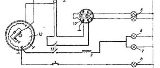
Electrical circuit of the Voskhod motorcycle
Central switch. 2. speedometer. 3. Speedometer light. 4. Headlight. 5. Headlight lamp. 6. City driving lamp. 7. Sound signal. 8. Direction indicator lamp. 9. Direction indicators. 10. Direction indicator switch. 11. Electronic switch. (D - sensor terminal, K - ignition coil terminal, G - generator terminal.) 12. Throttle. 13. Relay breaker. 14. Generator. 15. License plate lamp. 16. Brake signal lamp. 17. Rear light. 18. Wire connection block. 19. Brake light switch. 20. Shielded spark plug cap. 21. Spark plug. 22. High voltage wire. 23. Ignition coil. 24. Light switch.
Wire colors: sn. - blue, cf. - gray, g. - blue, g. - yellow, h. - green, k. - red, kor. - brown, op. - orange, f. - violet, h. - black.