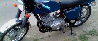
Electrical equipment IZH Planet 5
Wiring for IZH Planet 5 includes:
- generator;
- battery;
- ignition system;
- headlights;
- control devices;
- switching elements.
Video: review of IZH Planet 5 wiring
Taken by user Agronom.
Generator
IZ Planet 5 generator design:
- voltage regulator with rectifier BPV-14-10 - 1;
- rotor - 2;
- stator with windings - 3;
- current collector brushes - 4;
- ignition system cam (battery) - 5;
- ignition system contact unit - 6.
The generator converts the mechanical energy of a gasoline engine into electrical energy, which charges the battery. Alternating current is generated by 3 windings and fed to a rectifier, which converts it into direct current. An additional coil is used as an exciter.
Photo gallery: IZH Planet 5 generator and its design
Battery
To supply all components, a low-power energy storage device of 12 volts is required, since IZH Planet 5 does not have a starter. The purpose of a lead-acid battery is only to supply voltage to the ignition system and the excitation winding of the generator during startup.
Ignition system
In IZH Planet 5, the ignition coil converts low-voltage voltage into high-voltage and transmits it to the spark plug. That, in turn, is responsible for the spark that detonates the fuel. To ensure that detonation occurs only in the desired piston position, there is an ignition chopper.
From the factory, this model is equipped with a classic ignition system, which requires periodic cleaning of the breaker contacts and adjusting the gap between them.
Installing a contactless SG on a motorcycle gives:
- timely powerful sparking;
- reduction of vibration levels;
- reduction in fuel consumption.
Control devices
The following control devices are installed on the motorcycle:
- tachometer, on which there are indicator lights for the headlights and turns;
- speedometer showing total and daily mileage;
- power engine temperature indicator;
- voltmeter.
Headlight and dashboard lamps
Conventional incandescent lamps are installed as lighting equipment and to illuminate the dashboard. Switching elements are responsible for supplying electricity from the battery to the lamps.
The headlight circuit includes lamps:
- headlight (35 watt);
- parking light headlights (4 W);
- control - blue light (2 watts);
- rear brake light (15 W).
Switching elements
Switching elements are various types of switches that close or open an electrical circuit. They can be activated using keys on the dashboard (for example, turn signals) or by sensors.
In IZH Planet 5, the switching elements include:
- turn switches;
- signal key;
- switches for low/high beam headlights;
- neutral sensor;
- egnition lock;
- foot and hand brake sensors.
Model features
Therefore, even today, enthusiasts retrieve famous motorcycles from dusty sheds and garages, restore them to their original form and, as before, give the spirit of freedom to their owners.
Taking a motorcycle out of the woodshed, there is hope that it will return to service again
What is especially pleasing is the interest of modern youth in domestic technology. This article is intended for them and their parents who had the opportunity to ride Izhaks, Jupiters and Planets .
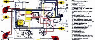
Electrical diagram
The IZH Jupiter 3 model appeared as an improved example of the previously produced IZH Jupiter 2. For the first time in domestic practice, a motorcycle received turn signals, and therefore the wiring diagram of the IZH Jupiter 3 has undergone changes.
In particular:
- There was a separate cable running under the gas tank and seat to the rear turn signals;
- For the model with a side trailer, a second cable was laid and attached to the stroller frame.
The new model is based on the proven electrical circuit of its predecessor.
The photo above also shows the wiring for the IZ Jupiter 3 in the version with a sidecar.
They asked from her:
- Lamp (yellow) for trailer brake lights (indicated as 2a in the diagram);
- Lamp (red) for the rear marker light of a trailer (3a);
- Right direction indicator on the trailer fender (11);
- Trailer front marker light (white) (17).
One can argue for a long time about the quality of products of the domestic motorcycle industry, but a motorcycle in capable hands required only preventive maintenance and adjustment. And the era of shortages forced owners to show miracles of ingenuity, modifying unreliable components and assemblies of their two-wheeled horses.
For reference: Izh Jupiter 3 deservedly received the Quality Mark. This was evidenced by a sign on the frame - in the photo below. Today, finding such a motorcycle without “crooked” improvements is a great success for collectors.
In comparison with imported “disposable motorcycle junk”, Planet 3 in capable hands served for decades
Self-improvement
Many were not satisfied with the capricious ignition of the motorcycle (see the article wiring diagram for IZH Planet 3), so the wiring diagram for IZH Jupiter 3 was often changed from 6 to 12 volt. This was facilitated by the appearance of the 281.3701 generator produced by the Izhevsk Motor Plant, which was much better and more reliable than the standard G36M7. Those owners who were not able to get it had to upgrade the existing one.
For this:
- A steel adapter plate was machined, allowing 12 internals to be installed in the generator;
- The right engine cover was purchased or exchanged from older models Jupiter 5 or Planet 5.
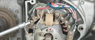
Exterior view of modified crankcase with steel plate
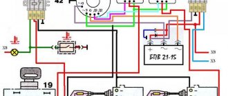
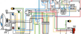
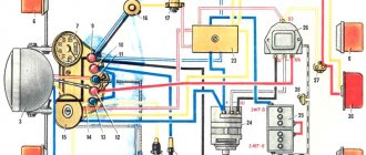
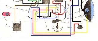
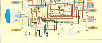
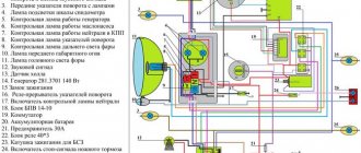
Wiring diagram IZH Planet 5
Detailed color wiring diagram for motorcycle IZH Planet 5
Explanations for the diagram
The numbers on the electrical diagram correspond to the following elements:
- Light switch, dimensions/low.
- Light switch, direction indicators and horn buttons.
- Front turn signals.
- Instrument panel lighting.
- Indicator lamp for generator operation.
- Oil pump operation indicator.
- A light indicating the operation of the neutral gear in the gearbox.
- Direction indicators.
- High beam headlight indicator.
- Front parking light bulb.
- Headlight lamp.
- Sound signal.
- Hall Sensor.
- Generator.
- Egnition lock.
- Turn signal interrupter relay.
- Neutral gear warning lamp sensor.
- Block BPV 14-10.
- Switch.
- Battery.
- Fuse.
- Relay block.
- Ignition coil.
- Foot brake light sensor.
- Rear direction indicators.
- Rear light with lamps.
Description of the symbols for the terminals on the rectifier-regulator block BPV 14-10:
- –x1 — “minus” of the generator excitation winding;
- –x2 — “minus” of the battery (“ground”);
- x2 - “positive” wire to the control lamp of the instrument panel;
- x3 - “positive” wire to the panel indicator;
- x4, x5, x7 - phases of the stator winding;
- x8 - “plus” of the battery.
Electrical equipment IZH Jupiter 5
An important element of a motorcycle is a large amount of electrical equipment. The IZh electrical circuit includes the following elements:
- battery; — 12 volts
- generator: - 12 volts
- switch;
- headlight;
- dashboard;
- wiring;
- sound signal;
- turn relay, direction indicators;
- stop signal;
- charging relay;
- combination switch;
- ignition coil, spark plug;
- relay regulator;
- rectifier, fuses.
Given the presence of such a large amount of electrical equipment in the wiring on IZ Jupiter 5, many special terminals were used to fix connections, which made it possible, if problems were detected, to quickly disconnect the faulty element for repair or replacement.
To properly disconnect faulty parts, owners most often used the IZ Jupiter 5 color wiring diagram with a detailed description, which, if necessary, could also be used to determine how to connect certain elements of the circuit.
Maintenance
The owner can independently perform some maintenance procedures:
- check the motorcycle generator if the battery loses charge;
- set the gap between the breaker contacts;
- adjust the quality of the sound signal.
The need to inspect and adjust the wiring arises if:
- the motorcycle moves in the rain for a long time, as this causes oxidation of the contacts;
- a motorcyclist rides in an area with a lot of vegetation that damages wiring;
- The driver rides in snow in winter, which can stick to electrical wiring parts and damage them.
Self-check of the Planet 5 motorcycle generator in case of loss of charge
The cause of loss of charge in the IZH Planet 5 battery is most often a breakdown of the generator.
To check it yourself you need:
- multimeter device;
- straight screwdriver.
Step-by-step instruction
The following steps must be followed:
- Disconnect the wires from the battery and remove the generator cover.
- Disconnect the top 5 wires from the generator, first unscrewing their fastenings. In order not to mix up the wires during assembly, it is worth marking them.
- Measure the winding resistance using a multimeter in ohmmeter mode. To do this, you need to touch the body with one probe, and the other should be connected in turn to the 3 wires of the winding. There should be no short circuits, as indicated by the inscription on the multimeter screen.
- Test the resistance between the stator contacts: you need to touch them one by one with the multimeter probes. The value on the screen should be 8 ohms.
The presence of a short circuit in the 3rd stage or a discrepancy in the indicators in the 4th will indicate problems with the generator.
Photo gallery: stages of checking the IZH Planet 5 generator in case of loss of charge in pictures
How to correctly set the gap between the contacts of the breaker?
In order to set the gap between the breaker contacts, you will need:
- straight screwdriver;
- wrench 10;
- candle key;
- probe 0.4 mm thick (+/– 0.05 mm).
Next, you need to follow the steps sequentially:
- Place the motorcycle on a stand and place the gearbox in neutral.
- Remove the right crankcase cover and unscrew the spark plug.
- Using a 10mm wrench, grab the generator rotor mounting bolt and turn the crankshaft to a position where the contacts are as far apart as possible.
- Loosen the screw securing the contact.
- Place the probe between the contacts and adjust the tightening of the eccentric screw until the probe passes the contacts with little resistance.
- Tighten the contact fixing screw.
Photo gallery: adjusting the gap between the breaker contacts
Troubleshooting the audio signal and improving signal quality
Poor sound signal quality is mainly caused by improper adjustment.
The following tools will be needed for setup:
- wrench 7;
- a simple screwdriver.
Step-by-step instruction
To adjust, do the following:
- Loosen the locknut with a wrench.
- Turn on the ignition.
- Press the button to turn on the sound signal.
- Adjust the sound by rotating the adjusting screw.
- When the desired result is achieved, tighten the locknut.
Did you like the article? Follow our channel for new ideas of useful car tips. Subscribe to us in Yandex.Zen. Subscribe.
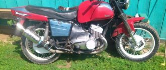
The road version of the IZH Planet 5 motorcycle differed favorably from other domestic analogues by the use of an oil pump, which made it possible to abandon the scheme for pre-mixing fuel with oil.
In addition, subsequent modifications were distinguished by their contactless ignition system, independent of the battery, and modified kinematics.
- To set the motorcycle in motion “from the pusher” - by turning on the ignition, the owner engaged second gear and, using his own efforts, pushing the motorcycle forward, started the engine;
- Operation without a battery was possible during daylight hours (a battery was still required for the side lights and headlights to operate).
Motorcycle Features
According to industry norm, the motorcycle had an alphanumeric index:
- IZH 7.107-010 – basic model;
- IZH 7.107-020 was already equipped with a new lubrication system and improved front axle suspension. In addition, the wiring diagram of the IZH Planet 5 motorcycle had a contactless ignition system, independent of the battery;
- IZH 7.107-030 was equipped with a spring-hydraulic shock absorber and a redesigned rear wheel brake drive;
- IZH 7.107-040 was produced with modified kinematics and a modified front wheel brake. The wiring diagram on IZH Planet 5 remained contactless until 2008.
Electrical equipment IZH Planet 5
The motorcycle uses 12-volt electrical equipment. The electrical wiring of the IZH Planet 5 motorcycle is single-wire, the role of the negative wire is performed by a metal frame.
Among the main components are:
- Power supplies;
- Ignition system;
- Headlight;
- Side lighting and turns.
For reference: as is customary in auto and motorcycle construction, modification of components and assemblies allows you to reduce the cost of products. For consumers, the advantage is that the price is low and a number of parts are interchangeable.
Generator
The motorcycle is equipped with a three-phase alternating current generator with an electromagnetic excitation circuit.
The principle of its operation is as follows:
- Electric current from the windings located on the stator is supplied to the rectifier;
- It converts it to direct current;
- And supplies it to consumers through the ignition switch.
The instructions provided include the following items:
- Voltage regulator with rectifier BPV-14-10;
- Generator rotor;
- Generator stator with windings;
- Current collector brushes;
- Ignition system cam (battery);
- Ignition system contact unit
For reference: on three-phase generators of the IZH Planet 5 motorcycle, the windings are connected according to a “star” or “delta” circuit. The rectifier is installed as a separate unit, and the IZH Planet 5 electrical wiring is connected to it.
Headlight
Unlike European countries, where there is a requirement that motorcycles with permanent magnet generators must be equipped with a battery - since a motorcycle with a non-working engine must have side lights - there are no such restrictions in Russia (see also about the Ural motorcycle wiring diagram).
For reference: with such a generator, IZH Planet 5 did not need an external current source when starting the engine. Therefore, the battery was not included in the electrical equipment.
The head light circuit includes:
- headlight lamp (35W);
- blue indicator lamp (2W);
- headlight parking light (4W);
- rear brake light lamp (15W).
Control devices
The following control devices are installed on the motorcycle:
- speedometer with daily and total mileage counters;
- tachometer with indicator lamps for direction indicators and headlights;
- engine temperature indicator;
- voltmeter.
Changes made by owners
The unreliability of individual components and faulty wiring on IZ Jupiter 3 forced the owners to delve into all the intricacies of the modernized elements.
And the first to cause numerous complaints were changes in the primary circuit of power supplies:
- Battery;
- Generator.
As well as ignition systems and circuits for lighting devices of the trailer module - a cargo-passenger stroller. In most cases, the reason for the refusal was a banal manufacturing defect.
Redesigned color wiring diagram for IZ Jupiter 3
Battery charging system
Given the total shortage of spare parts for motorcycles that existed in those years, unplanned failure:
- battery;
- voltage regulator relay;
- ignition coils;
left the owners without transport for a long time. In addition, poor-quality assembly of individual elements led to unstable operation of all systems. This forced me to improve and polish the factory defects with my own hands (for example, see how to modernize the wiring diagram of IZH Planet 5).
Wiring IZ Jupiter 3: structure of a modified relay regulator
Tip: the regulator circuit presented above has been tested on many motorcycles of the IZh family. Its peculiarity lies in the separate power supply - when turned on, the ignition circuit receives “+” from the battery. And the excitation windings are powered from the generator (terminal “I”) and do not discharge the battery when the engine is stopped.
Generator replacement
The operation of the standard G36M7 DC generator also caused a lot of comments. Frequent breakdowns and unstable operation forced the owners to look for a replacement.
The new modifications of the IZh family with 12-volt generators that appeared immediately attracted the attention of the owners of the IZH Jupiter 3, who were able to find a way to convert their motorcycle to a new operating scheme (see also the IZH Jupiter 5 wiring diagram).
The standard generator IZ Jupiter 3 could not cope with its duties
And among those that were freely available was the generator 281.3701, suitable for all series of “Planets” and “Jupiters”.
To re-equip the work it was required:
- Working generator 12 V;
- Block BPV 14-10;
- New 12-volt battery 6MTS-9, or another battery ZMT-8 (standard);
- New 12-volt light bulbs (to replace standard ones with 6V ones);
- Steel adapter plate for mounting a new generator;
- Right engine cover from IZH Planet 5 or Jupiter 5 models.
Photo of the blank for the adapter
Advice: DIY alteration of the cover for a new generator can result in damage. Therefore, experienced owners recommend purchasing an original cover from “older” models, which was originally designed for its mounting dimensions.
The instructions for installing a new generator are very simple:
- The adapter is installed in the right half of the crankcase;
- Fixed with short bolts with a diameter of 6 mm;
- The stator of the new generator is connected to the adapter through M5 threaded holes using three screws.
This is what the crankcase with adapter looks like