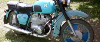
In 1970, the IZH Planet 3 model appeared in the production program of the Izhevsk Motor Plant.
Unlike its predecessor with the index “2,” the motorcycle received a new shaped gas tank, a more powerful engine and direction indicators.
Unification of the electrical circuit with other models is a traditional way to reduce costs
Motorcycle Features
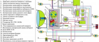
The electrical wiring of IZH Planet 3 was designed for 6 volts. It served as the basis for other motorcycle models produced later (see also wiring diagram for IZH Planet 5).
Among the features are:
- Generator G36M7, which was later modified;
- Voltage regulator relay RR-1;
- Ignition coil IZH 56;
- Turn signal relay PC419.
For reference: The installation of markers and turn signals was used for the first time on domestic motorcycles. In general, for its progressive design and high quality, the IZH Planet 3 model received the state quality mark, which can be seen in the video of previous years.
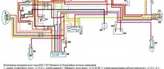
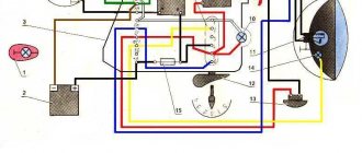
Original and color wiring diagram for IZH Planet 3
4 years after the appearance of the second Planet (1966), the factory workers made a number of changes to its design, designed to improve the technical parameters and appearance of the motorcycle. This is how IZ Planet 3 was born, which became a real symbol of freedom for many of our compatriots.
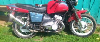
Despite its advanced age, IZH Planet 3 still serves its owners well
Converting the electrical circuit to work without a battery
Unlike cars that have a closed engine and electrical wiring, parts of the IZH Planet 3 motorcycle are more susceptible to external factors than others:
- Rain and snow;
- Direct sunlight;
- Mechanical damage from bushes.
The owners are especially troubled by the standard battery, which is also quite difficult to maintain (see also the Ural motorcycle wiring diagram).
The factory instructions provide:
- The need to constantly check the electrolyte level in banks, because when the motorcycle tilts, it inevitably leaks out;
- The need to constantly check the electrolyte density. This forces motorcycle owners to have a hydrometer, distilled water and hydrochloric acid on hand to restore the required density with their own hands.
Differences from the second Planet
For many modern citizens, the information that domestic motorcycle manufacturers worked tirelessly to improve their models in an era of total shortages may come as a surprise.
Note! The fact takes place, moreover, it is supported by official documents, in particular 1970N04P16-17 - this is the outgoing number of the factory newsletter, which described the changes made.
In the photo - official materials of the Izhmash Design Bureau
The new generation motorcycle received:
- Direction indicator lights are a first in domestic practice;
- Semiconductor relay for controlling direction indicators (installed in the headlight);
- New size of wheels and tires (3.50x18 versus previous - 3.25x19);
- New brand increased capacity battery (old one on IZH Planet 2 - ZMT-6);
- And, of course, more engine power. The power unit now developed 18 hp.
Modifications
But the creator engineers did not stop there and, having released the five-millionth car from the production line, presented a modification of the IZH Planet 3-01.
Mirror and safety arches are the distinctive features of the new modification
Among the innovations it should be noted:
- Rear passenger footrests;
- Roll bars;
- Rearview mirror;
- New steering wheel design.
For reference: The buyer paid for the changes out of his own pocket. In particular, the price for IZH Planet 3-01 was 750 rubles, the version with a stroller was 1140, and the “rural version” was even more expensive. Fortunately, care instructions were included with purchase, which made maintenance easier.
Stages of electrical equipment modification
The entire procedure for switching to a battery-free circuit comes down to:
- Replacement of components for 12 volt equipment;
- Remaking the generator, and sometimes borrowing it from another model;
- Replacing lamps from 6V to 12V.
For reference: the wiring diagram on IZH Planet 3 does not change significantly - only the circuits of the generator, coil and voltage regulator relay are replaced.
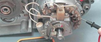
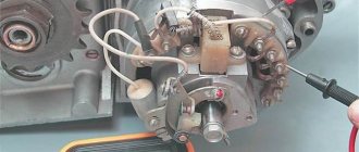
Generator
The main difficulty in altering the generator lies in the manufacture of a special intermediate ring. This requires the help of a turner - the ring is turned on a lathe.
Photo of the drawing of the intermediate ring for the generator
Also in the ring:
- Two 6 mm holes are drilled to allow the ring to be secured on the right half of the crankcase;
- To attach the generator to the ring, three M5s are drilled;
- A segment is cut out of the ring to facilitate installation under the partition of the right half of the crankcase;
- Cutouts for the crankcase cover bosses are made on the right and bottom.
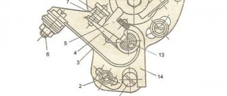
Diagram of the modified generator
The numbers on the diagram indicate:
- Carter - right half;
- Power unit crankshaft;
- Intermediate flange mounting screws;
- The intermediate flange itself;
- Conical bushing made of sheet metal (S 0.8 mm);
- Generator stator;
- M5 screws for mounting the generator;
- Generator rotor;
- Rotation sensor;
- Rotor mounting bolt.
Electrical diagram
When converted to work without a battery, the wiring diagram of the IZH Planet 3 motorcycle remains standard:
- Wires to electricity consumers (dimensions, brake lights, head lights and instruments) remain unchanged;
- The standard ignition coil is replaced with another one - type B300B;
- The KET-1 electronic switch can be placed in a tool box, which helps protect it from external factors.
Advice: motorcyclists who have done this modification note the undoubted advantages of switching to contactless ignition. The wiring of IZH Planet 3 remains almost unchanged, but there is a complete refusal to use the battery. And the cost of reconstruction is small.
Conclusions: the proposed conversion method has been tested on thousands of motorcycles of domestic owners (see also the IZ Jupiter 5 wiring diagram). And it has proven its worth with trouble-free operation, improved spark generation and reliable engine starting in harsh winter conditions.
Ignition adjustment
First you need to determine which contact is used for which cylinder. Set the contact gaps to 0.4 millimeters; if the cam is very worn, reduce the gap to 0.3 millimeters. Next, unscrew the spark plugs and set the piston in one cylinder to top dead center. Insert any clean stick instead of a candle and make a mark. Measure 3 millimeters from this mark and align the piston to the new mark. Using a screwdriver, loosen the contact plate of this cylinder. Insert tissue paper between the contacts and turn the plate counter-clockwise until the paper can be pulled out. Instead of paper, you can connect a light bulb, one wire to ground, the second to contact. Rotate the plate until the light comes on. The second cylinder is adjusted in the same way as the first.
After all the procedures, all that remains is to add oil and gasoline, the motorcycle is ready for use. Correct wiring is the key to long and flawless operation of the Izh Jupiter 3.
Required Parts
In order for the ignition system to work correctly, a number of auxiliary parts are required. They are listed below:
- Switch for BSZ VAZ cars. You should not choose exclusively from the low price segment. The Astro switch has a lot of positive reviews;
- Hall Sensor. The best option for Jupiter 5 is a similar manufacturer VAZ. By purchasing it in branded packaging, you protect yourself from counterfeits;
- Ignition coil with two terminals. You should choose between the gazelle engine number 406 or Oka with an electronic ignition system;
- A pair of silicone armor wires with rubber caps;
- The modulator is a butterfly-shaped plate made of iron.
Modulator
The most difficult stage is the production of the modulator
It is important to maintain the required shape. The more reliably the required dimensions are observed, the lower the likelihood of problems occurring after implementing the system, that is, there will be no need to adjust it using a file
The ignition timing must match on any cylinder used.
The bolt hole must be located in the middle. Otherwise, the engine operation will not be synchronized. It is also recommended to check the integrity of the crankshaft bearings. If you find defects, you should immediately replace it.
The contact ignition is not able to work normally if the bearings are damaged. The thickness of the part should not exceed one and a half millimeters. If it is thin, it will not be possible to avoid deformation, and if it is thick, it will come into contact with the surface of the hall sensor housing.
To create the plate, it is allowed to use any material except steel. Aluminum and others should not be used as they are not magnetic. The drawing that must be followed can be found in the public domain. The presented diagram will be useful to those people who decide to modernize the vehicle ignition device. Below are methods for installing electrical ignition devices in Jupiter. It must be turned by a professional turner. He will make a simple disk and draw on it the markings of elementary distances between the corners. Then, in accordance with it, you will cut out the necessary sectors at home. The cost of the modulator is seventy rubles.
It is not advisable to use an ordinary plate, since its width is less than twelve millimeters. This will not be enough to fully accumulate the energy resource in the coil. Of course, it can be installed, but achieving four thousand revolutions per minute will become impossible.
In addition to the above you will need:
- A stud with an applied thread of seven millimeters, pitch 1, as well as a pair of nuts with washers of the corresponding parameters. The priority material for these components is brass. This is explained by the least magnetization of the plate from the generator rotor. If you use a standard bolt, then difficulties may arise with the implementation of the ignition. The bolt tends to follow the modulator as it is tightened. However, it is necessary to observe the leading indicator, maintain the same position of the rotor and modulator, and tighten the bolt. It is advisable to use a pin, since many are not able to perform all the necessary actions in total;
- A set of wires with connectors for ignition without contact from VAZ. This part can be purchased or made with your own hands.
Connecting wiring Izh Planet 3
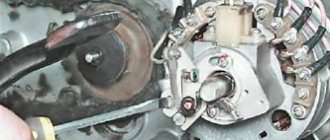
The sources of electric current on motorcycles of the IZH models are direct current generators (Fig. 62) with parallel excitation and a rated power of 45 W at 1700 rpm.
The generator stator contains 6 field coils connected in series. The following are mounted on the stator: terminal block 9, brush holders 8, breakers 1 and capacitors 7. Armature 3 has a winding consisting of 31 sections and a collector 10. On IZH-Yu motorcycles the G-36M2 generator is used, on IZH-P - G-36M1. The IZH-Yu2 and IZH-YUZ motorcycles are equipped with a G-36M8 generator, and the IZH-P2 and IZH-PZ motorcycles are equipped with a G-36M7 generator. Generators G-36M1, G-36M2 differ from G-36M7 and G-36M8 by additional resistance on the excitation coil. Therefore, to use the G-36M7 and G-36M8 generators on motorcycles IZH-Yu, IZH-P and IZH-56, it is necessary to install a relay-regulator PP-1, instead of a relay-regulator SB. 32. When installing a new IZH-YUZ or IZH-PZ engine on IZH-YU, IZH-P or IZH-56 motorcycles, the relay regulator is assembled. 32 you can not change, but only move the generator stator from the old engine to the new one if it is in good condition. Caring for the generator during operation comes down mainly to checking the fastening of the contact connections of the wires, the condition of the commutator and brushes. The collector can be cleaned with glass sandpaper. It is not recommended to use sandpaper - when cleaning, the sandpaper grains cut into the plates (lamellas) of the commutator and lead to rapid wear of the brushes.
Possible generator malfunctions:
sticking of brushes in brush holders;
contamination of the inter-lamella grooves or wear of the collector; short circuit of the generator windings to the housing or their turn circuit; the armature touching the stator due to improper installation of the stator, armature or wear of the right main bearing of the crankshaft; generator polarity reversal due to incorrect wire connection. To determine the causes and eliminate generator malfunctions, you must: 1. Remove the right crankcase cover. 2. Disconnect the wires from the terminal block. 3. Unscrew the screws securing the stator and remove it. 4. Unscrew the armature mounting bolt. 5. Screw the armature puller from the tool kit into the hole and remove the armature. 6. Remove the key from the groove of the axle shaft. After disassembling, wipe the parts with a cloth soaked in gasoline and inspect. Remove burrs from the working surfaces of the lamellas using fine-grained glass sandpaper. If the commutator is heavily worn, it can be machined on a tapered mandrel (taper 1:5), deepen the inter-lamella grooves to a depth of 0.5 mm and remove burrs. Paint over damaged insulation of excitation coils and bare areas of their terminals with enamel. Inspect the right axle shaft of the crankshaft and the cone hole of the armature. If there are nicks, clean them with fine-grained sandpaper. If there is large radial play, replace the right crankshaft main bearing. To install the generator in place:
1. Insert a key into the groove of the axle shaft and install the armature. 2. Place a spring washer and a breaker cam on the armature mounting bolt. 3. Screw in and tighten the bolt, making sure that the armature shaft antenna fits into the cam groove. 4. Lift the brush wires in the brush holder and install the stator in place, while the pin on the right half of the crankcase should fit into the groove at the end of the stator. 5. Secure the stator with screws and connect the wires to the terminal block. After disassembling and assembling the generator, it is necessary to check the ignition timing and, if necessary, adjust it. Ignition adjustment is described in the “Ignition System” section.
REVERSE CURRENT RELAY
. In a motorcycle electrical system, the battery and generator are connected in parallel. With an increase in the number of engine crankshaft revolutions, the number of revolutions of the generator armature increases, and therefore its voltage. Therefore, if there is no regulating device in the generator-battery circuit, then the battery will be systematically recharged when the generator voltage increases, which will lead to its failure. If the generator voltage is lower than the battery voltage, the battery will be discharged through the generator, which may also become unusable. The functions of such a control device are performed by a reverse current relay (ROT) (Fig. 63). To ensure the normal operation of consumers installed on the motorcycle, as well as the rational mode of charging the battery within specified limits, a special device is included in one block with a reverse current relay - a voltage regulator (VR).
The reverse current relay consists of an electromagnet core 4, an armature 3 with a spring 12, two contacts 1, 2 and a yoke 13. Two windings are wound on the core: a thin shunt winding (SHO) and a thick series winding (CO). In the free state and at idle (low) engine speeds, the contacts are open and all consumers receive power from the batteries. As the generator armature speed increases, the voltage in the network increases. Accordingly, the current passing through the thin winding (WW) increases, the attractive force of the core overcomes the force of the spring, the armature is attracted to the core, the contacts are closed, and the electric current from the generator goes to charge the battery and to other consumers. As soon as the generator voltage drops below e. d.s.
batteries, the relay contacts will open under the action of the spring.
VOLTAGE REGULATOR
consists of an electromagnet core 7, an armature 6, fixed and moving contacts 5, a return spring 8 and resistances 9, 10. Three windings are wound on the voltage regulator core: shunt winding - SHO, compensation winding - KO and serial winding - CO. When the generator armature does not rotate or rotates at a low speed, the two-way movable contact of the voltage regulator is pressed against the upper fixed contact connected to ground by the force of the armature spring. In this case, the excitation winding 11 of the generator is connected to ground through the compensation winding KO and contacts b of the regulator. With an increase in the number of revolutions of the generator armature, the electric current flowing through the series winding magnetizes the electromagnet core and attracts the armature 6 of the regulator and its two-way contact 5 moves to the middle position, that is, it opens. In this case, resistors 10 and 9 of 4.4 and 1.2 ohms connected in series are included in the circuit of the excitation winding of the generator and the compensation winding. With a further increase in the armature speed, the additional resistance is not enough to prevent the generator voltage from increasing above the specified limit. Armature 6 is strongly attracted to the electromagnet and double-sided contact 5 is pressed against the lower fixed contact, short-circuiting the excitation winding of the generator. The generator voltage decreases, the armature of the voltage regulator returns to the middle position or closes with the upper fixed contact. Vibrating, armature 6 with double-sided contact maintains the generator voltage within 6.5 - 7 V. When the generator is overloaded, the series winding of the regulator, additionally magnetizing the electromagnet, limits the maximum generator current.
POSSIBLE MALFUNCTIONS OF THE VOLTAGE REGULATOR AND CARE FOR IT
. The voltage regulator is adjusted at the factory and this setting should not be changed unnecessarily. Maintenance comes down to monitoring the condition of the wires attached to the relay terminals and keeping it clean. A faulty voltage regulator disrupts the operation of the entire electrical system. The main signs of a malfunction are: bright burning of lamps or burnout. Electrolyte boils over and quickly discharges the battery, especially when operating the motorcycle at night. During operation of the motorcycle, control over the operation of the regulator is carried out using a red indicator light located in the headlight. The turning on of the control lamp at speed (1100 - 1200 rpm) indicates that the regulator or generator is not working properly. Operating the motorcycle with the warning light on will discharge the battery. The relay regulator is a very sensitive device and its adjustment can be entrusted to a highly qualified specialist.
CHECKING AND ADJUSTING THE VOLTAGE REGULATOR
is carried out at idle speed of the generator, that is, without any load. Therefore, it is necessary to lay an insulating paper pad between contacts 1 and 2 of the reverse current relay. In this case, the ignition coil will be powered by the battery. Connect a voltmeter to terminals “i” and “m”. Start the engine. At medium engine speeds, the voltage should be in the range of 7.3-7.8 V. If the voltage goes beyond these limits, then first you should clean contacts 5 with a steel plate (razor blade) 0.05 - 0.1 mm thick, but in no case with emery cloth. Cleaning should only be done with the engine not running. If stripping does not give positive results, you should check the gap between the armature and the core of the electromagnet 7 (0.9 - 1.1 mm), as well as between the contacts 5. The size of the gap between the contacts 5 is checked as follows: insert between the armature b and the core of the electromagnet 7 feeler gauge 1 mm thick and press the armature to the core. At this moment, the gap between contacts b should be 0.25 - 0.30 mm (checked with a second probe). If the gap is not maintained, it is necessary to bend the upper contact holder. Check clearances and voltage again. If necessary, the tension can be adjusted by changing the tension of the armature spring 8 by bending the lower spring holder. With increasing spring tension, the voltage in the circuit will increase, and with weakening, it will decrease. The spring holder must be bent when the engine is not running, and when checking the voltage with a voltmeter, the engine must be running at higher speeds. After completing the adjustment of the voltage regulator, remove the insulating gasket from the gap between the contacts of the reverse current relay.
CHECKING AND ADJUSTING THE REVERSE CURRENT RELAY
. To check and adjust the reverse current relay (ROT), you need an ammeter with a zero pointer position in the middle of the scale (scale 5-0-5A). The voltmeter is connected in the same way as when adjusting the voltage regulator, and the ammeter is connected in series to the battery. Before proceeding with the adjustment, it is necessary to check the compliance of the gaps, the size of which should be: between contacts 1 and 2 - 0.25 - 0.35 mm and between armature 3 and the electromagnet core - 0.6 - 0.8 mm. If it is necessary to adjust the gap between the armature and the core, the contact holder should be moved with the screws loosened. The gap between the relay contacts is adjusted by bending the contact post. To check the voltage, you need to start the engine and, gradually adding speed, notice the voltage at which contacts 1 and 2 close. At the moment the contacts close, the voltmeter needle shakes slightly. The contacts should close at a voltage of 6.0 - 6.4 V. The reverse switching current of the relay with correctly set gaps and switching voltage should be in the range of 0.5 - 4 A. If the contacts close at a higher voltage, then the lower spring holder 12 must be bent upward, weakening the spring force. If it is less, then bend the spring holder down. The adjustment is made at low speeds.
INSTALLATION OF RELAY-REGULATOR PP-1 ON MOTORCYCLES IZH-56, IZH-P, IZH-YU
. Relay-regulator PP-1 can be used instead of the sb regulator. 32, which is installed on motorcycles IZH-56, IZH-P, IZH-Yu. In this case, it is necessary to disconnect the additional resistance of the generator stator from ground and insulate the end of the wire. To install the relay regulator on these motorcycle models, it is necessary to make a special bracket (Fig. 64), which is mounted on the bolts of the tool boxes (the size is determined by the location of the bracket attachment). The old relay mounting bracket must be removed. To ensure normal operation of the new relay-regulator, the connecting terminals must be lowered down (Fig. 65).
Those who own a motorcycle with six-volt electrical equipment know that the weakest point is charging. Either the battery suddenly runs low and starting the motorcycle is a problem, then the charge disappears somewhere and magically returns, sometimes you have to ride at night without a headlight so as not to completely drain the battery... The electronic relay-regulator is an analogue of the PP-1 (voltage regulator and reverse current relay) and will save you from these problems forever. No additional modifications to the motorcycle wiring diagram are required. The circuit contains a minimum of parts that have many analogues.
This relay is applicable for motorcycles Izh-56, Izh P-1,2,3, Izh Yu-1,2,3, Java “Starushka”, Java-634, Ural and Dnepr with six-volt equipment.
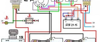
The relay diagram is shown in the figure. In the initial state, the zener diode VD1 and transistor VT1 are closed, and VT2 is open, since voltage is applied to its base through resistor R3. Thus, current flows through the field winding (W) and the generator generates voltage.
As soon as the voltage in the on-board network exceeds the set threshold (7.2 V), the zener diode will open and a control voltage will be supplied to the VT1 base, which will cause it to open and R3 to be shunted. Transistor VT2 will close, de-energizing the field winding. The voltage in the on-board network will decrease and the cycle will repeat. Diode VD2 is necessary to absorb emissions of self-induction EMF of the generator excitation winding.
Setting up the device consists in adjusting the opening threshold of transistor VT1 with resistor R1. To do this, we connect the assembled device to the laboratory power supply to terminals I “+” and M “-”. We connect a low-power light bulb in parallel to the VD2 diode or monitor the presence of voltage with a tester. Smoothly adjustable power supply voltage from 5 to 8 volts. With resistor R1 correctly configured, the light bulb should light up at a voltage of 7.2 volts. It should be taken into account that the voltage in the network will be 0.6 volts less than the operating threshold of our relay, since a voltage drop will occur across the VD3 diode.
The diagram shown in the figure below explains the operation of the relay with the G36 generator.
Any small-sized tuning resistor R1 with a resistance of 2000...470 Ohms, preferably multi-turn for more precise adjustment. R2 R3 with a power of 0.5...0.125 W, may differ from the indicated ratings by up to 50%. The zener diode can be replaced with any one with a breakdown voltage of 4.7...6.2 V. In extreme cases, you can use a chain of 7-8 silicon diodes in direct connection. Diode VD2 is any silicon diode with a reverse voltage of at least 100V and a maximum forward current of at least 1A, and VD3 - at least 10 A. VT1 is any silicon NPN transistor of medium power. KT606 has a convenient housing that can be easily secured for wall-mounted installation. VT2 can be replaced with any NPN structure transistor with a collector current of at least 5 A, although in this case it may be necessary to replace R3 with a 200..300 Ohm resistor with a power of 0.5 W.
In 1970, the IZH Planet 3 model appeared in the production program of the Izhevsk Motor Plant.
Unlike its predecessor with the index “2,” the motorcycle received a new shaped gas tank, a more powerful engine and direction indicators.