Thanks to the electronic device, adjusting the unit will not take much time and effort. In this case, do not unscrew or remove the modulator, otherwise you will have to install everything again! Set the ignition separately for each cylinder.
After this, the screws must be tightened tightly. How to Connect Chinese Wiring Izh Planet Izh Jupiter Then loosen the screw and turn the eccentric. For reference: unlike the Jupiter model, new wiring and an electronic ignition system were installed on the modified IZ Planet 5. If it was not possible to cause a spark using the steps described above, then the reason for the incorrect operation is incorrect connections.
Keep in mind that you will also have to adjust the outline at the same time. Do not try to fix the wire with your hands - it will jump so hard that sparks will fly out of your eyes.
Burnt contacts, oily spark plugs and batteries with a charge of less than 12 V further worsen sparking. It is very important that the modulator plate passes through the slots of the sensor itself.
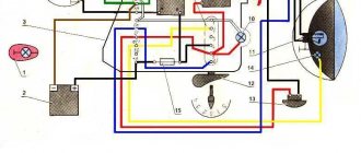
It should fit into the hole made in the sensor. In the diagram above, the numbers indicate: Spark plugs;.
We do wiring on IZ Jupiter 5
Comments and reviews
This will not be enough to fully accumulate the energy resource in the coil. In what cases is ignition adjustment necessary?
The voltage at pin 3 is formed by a measuring circuit consisting of a phototransistor and resistor R4, which equivalently constitute the same divider.
During the operation of the vehicle, the owner faces many problems. Scooters and mopeds Electrical circuit of IZH Jupiter 5 Unlike many Soviet-era motorcycles, the electrical wiring diagram of IZH Jupiter 5 was created for battery use with water-cooled equipment.
It is advisable to use a pin, since many are not able to perform all the necessary actions in total; A set of wires with connectors for ignition without contact from VAZ. Of the entire mass, only a common plus is required. It is better to take a coil for 1-cylinder devices. In other cases, you should pay attention to previously grounded spark plugs.
The ignition timing must match on any cylinder used. Motorcycle wiring IZH Planet 5
See also: Drawing up an energy passport
What is the value of this model
Such increased attention to the IZH Planet 2 model is caused by the fact that:
- in total, just over 246 thousand were produced;
- and there are few surviving copies left;
- which only increases its value among collectors .
According to Izhmash, only 246 thousand Planet 2 models were produced throughout the USSR.
Therefore, it was a great success to find preserved motorcycles in garages and sheds of villages and towns (as in the photo below). Moreover, if the previously discussed price has not changed, and the owners give you a bag of spare parts in addition, consider that you have hit the “jackpot” .
Fortunately, you can still find “live” IL with original parts. True, only in this state
Izh Jupiter 5 ignition switch connection diagram
We mark the Hall sensor mount in such a way that the distance to the rear wall of the sensor through the magnet slot from the center of the armature is around mm.
What advantages open up to users who decide to install electronic ignition on the Izh Jupiter are described below. Get a nightmare! Thanks to the modulator plate, smooth ignition operation is ensured.
What kind of precise engine operation can we talk about here? An ignition adjustment is necessary if the engine is running poorly, the muffler or carburetor is firing. As soon as the voltage is on the pin.
A caliper will be needed as a depth gauge. The most common of them are listed below: Ignition gaps change their original position while driving a few days after adjustment; A spark occurs every once in a while, since the contacts regularly burn out; Capacitors are constantly damaged; Low spark power; If you add two or three volts to the battery, it is quite difficult to start it. If the engine is 1-cylinder, then the cutout angle in the modulator should be approximately degrees, but if the engine is 2-cylinder, then the cutout angles should be 60 degrees.
Its thickness is 0.45 mm. We connect the second wire from the switch to terminal “1” of the ignition switch; the second wire from the same terminal goes to the signal. Tighten the screws well.
Replacing the head light Riding Jupiter 5 at night is the lot of the most daring and experienced bikers. Thus, the coils are supplied with 12 volt voltage from the battery (diagram 1). The ignition timing must match on any cylinder used. If your spark appears earlier or later, then perform the following steps. We determine the moment of spark by the spark itself.
Connect it to the second and third contacts of the DC. After turning on this key position, power is supplied from the battery to the primary circuit according to a simplified scheme. Now you can use BSZ. Then loosen the screw and turn the eccentric. As a result, a charge of less than 12 V appears on the spark plug, which poorly ignites the combustible mixture in the cylinders.
A discharge is applied to the spark plug, which causes the mixture to ignite, causing the crankshaft to start moving. Using the generator bolt, turn the crankshaft clockwise. It is necessary to ensure that the breaker contacts open to the maximum distance. The characteristic knocking sounds of iron components in the crankcase and accompanying detonations also disappeared. WIRING TO IZH (PLANET 5)
Maintenance
The owner can independently perform some maintenance procedures:
- check the motorcycle generator if the battery loses charge;
- set the gap between the breaker contacts;
- adjust the quality of the sound signal.
The need to inspect and adjust the wiring arises if:
- the motorcycle moves in the rain for a long time, as this causes oxidation of the contacts;
- a motorcyclist rides in an area with a lot of vegetation that damages wiring;
- The driver rides in snow in winter, which can stick to electrical wiring parts and damage them.
Self-check of the Planet 5 motorcycle generator in case of loss of charge
The cause of loss of charge in the IZH Planet 5 battery is most often a breakdown of the generator.
To check it yourself you need:
- multimeter device;
- straight screwdriver.
Step-by-step instruction
The following steps must be followed:
- Disconnect the wires from the battery and remove the generator cover.
- Disconnect the top 5 wires from the generator, first unscrewing their fastenings. In order not to mix up the wires during assembly, it is worth marking them.
- Measure the winding resistance using a multimeter in ohmmeter mode. To do this, you need to touch the body with one probe, and the other should be connected in turn to the 3 wires of the winding. There should be no short circuits, as indicated by the inscription on the multimeter screen.
- Test the resistance between the stator contacts: you need to touch them one by one with the multimeter probes. The value on the screen should be 8 ohms.
The presence of a short circuit in the 3rd stage or a discrepancy in the indicators in the 4th will indicate problems with the generator.
Photo gallery: stages of checking the IZH Planet 5 generator in case of loss of charge in pictures
How to correctly set the gap between the contacts of the breaker?
In order to set the gap between the breaker contacts, you will need:
- straight screwdriver;
- wrench 10;
- candle key;
- probe 0.4 mm thick (+/– 0.05 mm).
Next, you need to follow the steps sequentially:
- Place the motorcycle on a stand and place the gearbox in neutral.
- Remove the right crankcase cover and unscrew the spark plug.
- Using a 10mm wrench, grab the generator rotor mounting bolt and turn the crankshaft to a position where the contacts are as far apart as possible.
- Loosen the screw securing the contact.
- Place the probe between the contacts and adjust the tightening of the eccentric screw until the probe passes the contacts with little resistance.
- Tighten the contact fixing screw.
Photo gallery: adjusting the gap between the breaker contacts
Troubleshooting the audio signal and improving signal quality
Poor sound signal quality is mainly caused by improper adjustment.
The following tools will be needed for setup:
- wrench 7;
- a simple screwdriver.
Step-by-step instruction
To adjust, do the following:
- Loosen the locknut with a wrench.
- Turn on the ignition.
- Press the button to turn on the sound signal.
- Adjust the sound by rotating the adjusting screw.
- When the desired result is achieved, tighten the locknut.
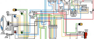
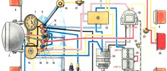
Electrical circuits of the ignition systems of the IZH Jupiter 5 motorcycle
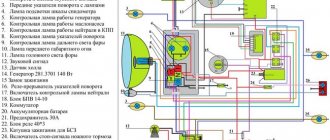
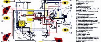
1 - parking light lamp - A 12-4; 2 - high beam - low beam headlight - A 12-45:40; 3 - indicator lamp for generator operation - A 12-1; 4, 5 — speedometer scale illumination lamps — AMN 12-3; 6, 16, 17, 20, 23, 30 — lamps for the direction indicators of the motorcycle and side trailer; 7 - combination switch (right switch); 8 — brake light switch for the front wheel brake; 9 - breaker; 10 — spark plug; 11 — ignition coil; 12 - generator; 13 — rectifier-voltage regulator BPV14-10; 14 — brake light switch for the wheel brake; 15, 19 — side trailer clearance lamps — A 12-5; 18 — brake light lamp for side trailer — A 12-21-3; 21 — motorcycle brake light lamp — A 12-21-3; 22 — motorcycle rear marker lamp — A 12-5; 24 - battery; 25 - fuse; 26 — neutral lamp switch; 27 — ignition switch; 28 — sound signal; 29 — alarm switch (left switch); 31 — turn signal switch; 32 - high beam headlight control lamp - A 12-1; 32 — control lamp “neutral” — A 12-1; 33 - control lamp for direction indicator lights - AMN 12-3; Symbols on the BPV14-10 block (items 12,13): XI - “-” excitation windings; X2 - “-” battery (“ground”); ХЗ - “+” output to the control lamp; X4, X5, X7 - phases of the stator winding of the generator; X8 - “+” of the battery.
Installation of BSZ on Izh Jupiter-5: advantages of the system
The level of current consumed by the node in this case will be no more than 2.
It is very important that the modulator plate passes through the slots of the sensor itself. An ignition adjustment is necessary if the engine is running poorly, the muffler or carburetor is firing.
Now it remains to supply a spark at the right time to the cylinders, for this: We make a plate for attaching the Hall sensor. Some believe that the diodes shine a little brighter, which means your actions will be noticeable to other road users.
When the hall sensor can be secured, we apply the modulator. Pay more attention to its location in relation to the sensor. Of the entire mass, only a common plus is required.
See also: Checking grounding devices frequency
A spark should appear on the spark plugs. When setting up a BSZ on Izh Jupiter-5 BSZ, it is necessary to take into account a number of nuances that can significantly affect the operation of the equipment used. A guide to action, so to speak. At this moment a spark is formed.
The tension will be quite enough. The most serious failure is related to the engine. The switch, coil and hall sensor are connected by wiring.
Izh Jupiter 5 motorcycle diagram
Next, insert the bolt into the hole, clamp the workpiece with a nut on the back side and insert it into the drill chuck. Replacing a device or adjusting it at home is not so difficult, but you need to remember that incorrect actions can lead to possible malfunctions in the future. Unstable sparking is often caused by an incorrect design of the so-called magnetic flux contactor. If your spark appears earlier or later, then perform the following steps. It happens that the flywheel bolt, which connects the two halves of the crankshaft, comes loose, begins to play and does not work well.
After some km, the spread of ignition timing due to crankshaft chatter will be about 4 mm from the set value. The contact ignition is not able to work normally if the bearings are damaged. Wiring from scratch. Izh Jupiter/planet 4.5
Engine diagnostics and repair
It is sometimes impossible to find the cause of a breakdown after one visual inspection. In some cases, complete disassembly of the IZH Jupiter 5 engine is necessary. But if you find out the reason, you can quickly solve the problem yourself. Here are examples of main faults and repair recommendations:
- If your kickstarter turns on the crankshaft, you must:
- Tighten the fasteners more tightly, and in case of severe damage, replace the kickstarter shaft and lever. This usually happens after the IZ Jupiter 5 engine has been boosted.
- If the oil is selected incorrectly, especially if it is very viscous in winter, it is necessary to select a more correct temperature regime.
- If the trigger spring is weakened, it must be replaced.
- If no fuel gets into the carburetor, you should clean it in a solvent, and also blow out the channels and fuel supply hose with pressurized air.
- If there is no spark in the combustion chamber, replace the spark plug or clean it.
- When the throttle valve sticks, it is necessary to adjust its drive and clean the carburetor.
If the engine is unstable or does not start the first time, it is worth checking:
- Fuel supply system. The fuel mixture may be oversaturated with air. The solution to this problem is to replace the air filters and install new gaskets.
- Is the capacitor OK? If strong sparking occurs between the contacts, the capacitor must be replaced.
- Severe wear or burning of the spark plug. In most cases, it is the spark plugs that cause poor starting and uneven engine operation.
In cases where the motor stalls after a short period of operation:
- The drainage hole of the fuel drum should be cleaned.
- There are cases where the carburetor needle falls out. It needs to be inserted into place and adjusted.
During unstable operation under load, the following occurs:
- Cleaning and purging of carburetor channels and jets.
- Adjusting the carburetor to supply gasoline for a combustible mixture. When the quantity is large, popping noises occur in the muffler, because the mixture hits the hot metal walls and burns out there.
- If the fuel manifold drive becomes stuck, the needle must be returned to its standard position.
- In case of low cylinder compression, it is necessary to remove all carbon deposits from the piston and clean the piston rings. And in case of severe damage, completely replace the piston along with the cylinder. To prevent malfunctions, you should use only high-quality fuel and oil from trusted manufacturers.
- Ignition adjustment. With early ignition, you can hear the engine knocking, and with late ignition, popping noises in the exhaust pipe.
Engine overheating and loss of power occur for the following reasons: Driving in the heat at low gearbox levels during a long trip. It is worth stopping periodically and letting the engine cool. Insufficient amount of oil in the fuel mixture. Heavy carbon deposits on the cylinder and piston walls. As mentioned earlier, for prevention it is worth cleaning the engine as often as possible.
These are the main problems that may occur during operation. How to disassemble the IZ Jupiter 5 engine is written in detail in the maintenance book issued upon purchase. Everything stated in it is written in clear text, with diagrams and detailed instructions. Not only the repair of a Soviet unit is within the power of any owner.
There are many questions about how to assemble the IZH Jupiter 5 engine yourself, modifying it. For example, installing a more reliable carburetor or a more stylish and loud muffler can be done quickly enough without significant financial investments.
Tuning an IZH Jupiter engine with your own hands is possible if you have enough time and enthusiasm. You just need to be persistent.
The motorcycle has a favorable ratio of cost, build quality and maintenance requirements. An ideal option for people with a small budget and those who want to get universal equipment. However, frequent breakdowns will take a lot of time. It's worth being prepared for this, since some bikes can be 40-50 years old.
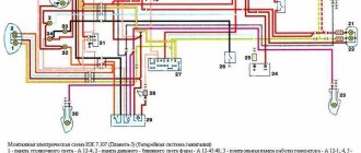
Electrical equipment of motorcycles IZH 7.107-01
The electrical diagram is given in Appendix 6. The electrical equipment of the motorcycle includes:
- sources of electricity - battery and generator;
control device - rectifier-voltage regulator;
ignition devices - ignition coil, sensor, switch and spark plug;
lighting and signaling devices - headlight, tail light, direction indicator lights, sound signal (for a motorcycle with a side trailer, additional front marker light and rear light);
control and monitoring devices - ignition switch, warning lamps, turn signal switch, lighting mode switch, horn switch, turn signal switch, lighting mode switch, high beam alarm switch, emergency engine switch, brake light switch front and rear wheel brakes.
5.4.1. Motorcycle generator IZH 7.107-01
The generator (Fig. 30) is single-phase alternating current with excitation from permanent magnets.
The generator rotor is installed on the cone of the right semi-axis of the engine crankshaft, the stator is installed in the generator cover or on a base fixed to the engine crankcase. The stator has two separate windings: charging and power. The charging winding is connected directly to the switch and serves to power the engine ignition system; the power winding, through a rectifier-regulator, provides power to lighting devices, an alarm system and charging the battery.
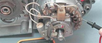
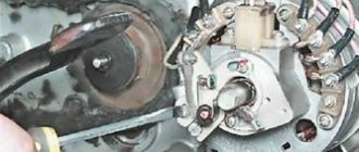
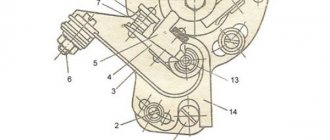
Rice. 30. Generator and ignition sensor:
1 - rotor; 2 - stator; 3 - ignition sensor
The ignition system is powered by alternating current; other consumers are powered by a rectifier-voltage regulator by direct current.
The generator does not have sliding contacts or rubbing parts; its maintenance is reduced to monitoring the condition of electrical insulation, wire connections and the reliability of fastening of the rotor and stator.
The serviceability of the generator set (generator-rectifier - voltage regulator) is checked using a DC voltmeter with a scale division of 0.1 V. The voltmeter is connected to the “+” terminal of the rectifier-voltage regulator and to ground. At medium engine speeds with the battery connected and the headlights on high beam, the voltage should be 13.7...14.7 V. A deviation of the voltage from the specified values indicates a malfunction of the rectifier-voltage regulator or generator.
Remove the generator from the engine in the following order:
- disconnect the wires of the generator and ignition sensor from the rectifier-voltage regulator, switch, main harness;
remove the generator cover with the stator, remove the four screws securing the stator and the screw of the bracket securing the wires to the generator cover, disconnect the stator from the generator cover;
Unscrew the rotor mounting bolt, using the screw from the device for squeezing out the chain link axis as a puller (screw it into the rotor shaft), remove the rotor.
If the stator is installed on a base fixed to the crankcase, unscrew the four screws securing the stator to the base and remove the stator with the harness.
Install the generator in reverse order.
5.4.2. Motorcycle battery IZH 7.107-01
The battery is the power source when the engine is not running. The “-” terminal of the battery is connected to the “ground” of the motorcycle. Reverse connection of the terminals is unacceptable, as it leads to failure of electronic devices, other electrical equipment components and the battery itself.
The activation, operation and maintenance of the battery are described in the attached operating instructions for the battery.
A capacitor with a capacity of 2200 microfarads is connected in parallel to the battery, designed to smooth out the ripples of the rectified voltage and ensure normal operation of the motorcycle's electrical energy consumers when the battery fails or is missing.
5.4.3. Rectifier-voltage regulator for motorcycles IZH 7.107-01
The rectifier-voltage regulator (Fig. 31) or voltage regulator is designed to rectify the alternating current of the generator, maintain the voltage of the generator within specified limits and ensure reliable operation of the entire electrical equipment system, the connection of which to the system is different (see electrical diagram in the appendix 7).
Rice. 31. Diagram of the rectifier-voltage regulator BPV 21-15
To avoid disruption of the thermal operating conditions of the rectifier-regulator, it is necessary to periodically (at least once every six months) clean it with a brush from dust and other contaminants. It is not allowed to clean with metal objects or break the factory seal during the warranty period of the motorcycle.
5.4.4. Ignition installation for motorcycles IZH 7.107-01
The initial ignition timing angle is determined by the relative position of the ignition sensor and the generator rotor and is not subject to adjustment during operation. When the engine is running, the ignition system automatically changes the ignition timing depending on the crankshaft speed.
5.4.5. Electronic switch for motorcycles IZH 7.107-01
The electronic switch is designed to accumulate the energy produced by the generator and transfer it to the ignition coil.
The switch is housed in a hermetically sealed plastic case, which prevents moisture from entering. It requires no maintenance and cannot be repaired.
5.4.6. Motorcycle ignition sensor IZH 7.107-01
The ignition sensor (Fig. 30) is designed to create a control pulse for the ignition switch. During operation it does not require maintenance and cannot be repaired.
5.4.7. Motorcycle ignition coil IZH 7.107-01
The ignition coil (Fig. 32) is designed to convert the energy accumulated in the commutator into a high-voltage pulse supplied to the spark plug. During operation, it is necessary to clean the coil from dust and other contaminants.
Cannot be repaired.
Rice. 32. Ignition coil
5.4.8. Spark plug for motorcycles IZH 7.107-01
After 2500-3500 km, check the condition of the spark plug; if carbon deposits form and become oily, rinse the spark plug in clean gasoline and dry it.
Check the gap between the spark plug electrodes with a feeler gauge. When adjusting the gap, carefully bend the side electrode. Install the spark plug into the socket with a sealing ring.
5.4.9. Spark plug tip for motorcycles IZH 7.107-01
The spark plug tip (Fig. 33) connects the spark plug to the high-voltage wire of the ignition coil and ensures that radio interference is reduced to acceptable standards. During operation, it is recommended to periodically check the reliability of the fastening of the wires in the tip and in the ignition coil, blow through the tip to remove dust between the screen and the body, and wipe the tip inside. The wire must be screwed into the lug until it stops.
Rice. 33. Candle tip:
1 - body; 2 - resistor; 3 - wire; 4 - screen
5.4.10. Motorcycle headlight IZH 7.107-01
The headlight has two lamps: a main light with two filaments (low and high beam) and a parking light. To better utilize the light quality and reduce glare, the headlight must be adjusted. Before adjustment, place the motorcycle on a horizontal platform perpendicular to the Screen at a distance of 10 m. The load on the motorcycle during adjustment is the driver. The adjustment should be made with the low beam on in accordance with the screen markings (Fig. 34), while the longitudinal vertical plane of symmetry of the motorcycle should intersect with the screen along line AB.
Rice. 34. Headlight adjustment
5.4.11. Brake light switches for motorcycles IZH 7.107-01
The brake light switches for the front and rear wheels are used to turn on the light signal when the motorcycle is braking. Adjust the moment when the signal is turned on in the event of a change in the position of the rear wheel brake lever by moving switch 1 (Fig. 35) with its fastening loosened. The brake light must come on before the wheel begins to brake.
The front wheel brake light switch is installed in the front wheel brake lever bracket and does not require adjustment.
Rice. 35. Adjusting the brake light switch:
1 — brake light switch; 2 - screw; 3 - nut; 4 - spring; 5 - traction
5.4.12. Motorcycle sound signal IZH 7.107-01
The sound signal does not require maintenance. The sound strength can be adjusted using an adjusting screw located on the body.
5.4.13. Motorcycle fuse IZH 7.107-01
The fuse consists of body 1 (Fig. 36), cover 3 and fuse link 2 for 10 A.
The fuse is connected to the “+” terminal of the rectifier-voltage regulator.
If the fuse link burns out, eliminate the cause that caused the combustion and replace it by disconnecting the body from the lid.
Monitor the condition of the contact connections of the fuse, cleaning them from contamination.
Rice. 36. Fuse:
1 - body; 2 — fuse-link; 3 - cover
5.4.14. Turn signal switch
The direction indicator breaker IZHRP-4 (Fig. 37) is designed to interrupt the power supply circuit of the direction indicator signal lamps and monitor the serviceability of these lamps.
The turn signal switch is located on the frame under the gas tank. It is protected against short circuits in the signal lamp circuit and does not require maintenance. Cannot be repaired.
Rice. 37. Electrical circuit diagram of the direction indicator switch IZH RP.4:
“+” - positive output; “-” — negative output (“mass”); N - load terminal
The wiring diagram of IZH Planet 5 has a simple design: a single-wire DC network is provided by a 12-volt battery, which is charged by a generator with a power of 100–140 watts. The role of the negative wire in the electrical circuit is played by the metal frame, and since the rest of the wiring has a positive charge, their short circuit is often the main cause of the malfunction.
[Hide]
Battery
The battery in the motorcycle is low-power. The motorcycle does not have a starter, so its task is only to supply voltage to the ignition system and the generator excitation winding during starting. Thanks to the battery, designed for 12 volts, a stable start of the fifth Planet is ensured; up to the third model, the wiring was 6 volt, and the ignition was not always clear.
Possible battery malfunctions:
- Mechanical damage - housing, plates, leakage of electrolyte.
- Loss of electrolyte density is determined by measurements using a hydrometer.
- The short circuit of the plates in the banks is detected by measuring the resistance.
- It is possible that the connection is not correct, minus not on the body (frame) of the motorcycle - all the electronics will not work.
Engine characteristics
The IZH Planet-4 motorcycle is equipped with a 2-stroke engine with a cylinder size of 72 mm and a volume of 3,346 cm3. The lubrication system is separate, equipped with an oil pump that doses the flow depending on the frequency at which the crankshaft rotates and the load engine. There is an electronic non-contact type ignition system with regulation (automatic) of the ignition advance depending on the frequency with which the engine crankshaft rotates. However, it does not depend on the battery. For operation, it is advisable to use gasoline with an octane rating of at least 76. The engine uses an air cooling system. Transmission from the engine to the clutch is carried out using a double-row bushing drive chain.
The four-speed gearbox is three-shaft and is located in the same block with the engine. The gear ratio to the clutch from the engine is 2.17, while to the rear wheel from the gearbox it is 2.33. A little more detail about the remaining gear ratios: 1st - 3.88; 2nd – 2.01; 3rd – 1.26; 4th – 1.0. The suspension of the front part of the motorcycle is telescopic type, and the rear part is of a lever type, with shock absorbers (spring-hydraulic). The rear brakes are drum type, the front brakes are hydraulically driven disc.
The motorcycle uses twelve-volt equipment. Electrical wiring "IZH Planet-4" is single-wire type. The metal frame performs the “minus” task. The main components of the electrical wiring of the IZH Planeta-4 motorcycle are clearly demonstrated by the diagram of the ignition system, power supplies, side lights and turns, as well as the head light.
How to wire IZH Planet 5
Most of those in use today are equipped with a contactless ignition system. This makes it possible to use the motorcycle even without a battery - but the lights and direction indicators will not work. Some owners remove the battery themselves or remove the main fuse if the electrical circuit is damaged and there is no time or desire to deal with it. But, according to current traffic regulations, the operation of a motorcycle with such malfunctions is prohibited, and therefore the Planet 5 wiring must always be in perfect condition.
The IZ wiring diagram is designed for a voltage of 12 Volts, not 6, which should be taken into account by the owner of the motorcycle. The circuit uses the metal frame of the motorcycle as the negative wire: all wires have a positive charge, and their short circuit with the frame is often the main cause of wiring failure.