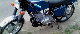
The main visual difference between the two motorcycles of the IZh family is the number of engine cylinders. The Jupiter 5 model has two of them, while the Planet 5 has only one.
In all other respects, the models are maximally unified with each other, with the exception of electrical components.
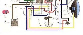
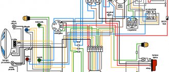
Colored wiring diagram for IZH Jupiter 5 air-cooled
For reference: another design feature of the IZ Jupiter of the last 5 years of production is the use of water cooling. And Planet 5 has all air-cooled engines.
Specifications[ | ]
- Overall length 2,115 mm.
- Overall width 780 mm.
- Overall height 1,025 mm.
- Ground clearance 135 mm.
- Dry weight of the motorcycle is 160 kg.
- Maximum speed 110 km/h.
- Fuel tank capacity 18 l.
- Cruising range on the highway is 400-450 km.
- Fuel consumption on the highway is no more than 4 liters per 100 km.
- Fuel: Gasoline with autol 10-18 in a ratio of 25: 1
- Fordability 300 mm.
- Engine Stroke 58 mm
- Cylinder diameter 61.75 mm
- Number of cylinders 2
- Engine displacement 347 cm3
- Compression ratio 6.8
- Maximum power 18 hp. With.
- Air cooling
- Lubrication system combined with fuel
- Carburetor type K-28ZH
Multi-disc clutch, in an oil bath with an automatic release mechanism. The gearbox is four-speed, two-way. Motor transmission is a rollerless double-row chain, gear ratio - 2.57. Transmission from the gearbox to the rear wheel is a roller chain, gear ratio - 2.33. The frame is tubular and welded. The front fork is a telescopic spring type with hydraulic shock absorbers. Rear suspension pendulum spring with hydraulic shock absorbers Type of brakes drum Type of wheels easily removable, with tangential straight spokes. Tire size 3.25-19″
Maintenance Features
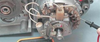
Often during operation it is necessary to correctly set the gap between the contacts of the breaker. To do this, you need tools and a diagram to see which elements need to be dismantled.
Wiring diagram for IZH Planet 5: connecting instruments and controls
The algorithm of actions is as follows:
- place the motorcycle on the stand;
- turn on neutral;
- unscrew the spark plug from the cylinder;
- remove the engine crankcase cover;
Breaker adjustment process
- turn the crankshaft until the contacts are as open as possible;
- using a screwdriver, loosen the locking screw;
- using a special feeler gauge, set the gap to 0.35-0.45 mm and fix it with a screw;
- we collect everything in reverse sequence;
The process of measuring the gap using a feeler gauge
- turn on the ignition and start the engine. Its stable operation at idle indicates that the adjustment has been correctly performed.
In general, all the wiring of IZH Planet 5 is very easy to do with your own hands.
The need for such work often arises when operating a motorcycle:
- in wet weather, driving in the rain for a long time (oxidation or dampness of electrical contacts);
- when traveling over rough terrain, replete with vegetation and bushes (mechanical damage to wiring);
- when used in winter (snow and slush stick to the wires and can damage them).
Often the sound signal suffers during operation. Its malfunctions manifest themselves in the form of deterioration in sound quality.
To restore its functionality, you must perform the following procedure:
- loosen the locknut using an open-end wrench;
- turn on the ignition;
- press the button to turn on the sound signal;
- use a screwdriver to adjust the tone;
- repeat the procedure until we get a clear and loud sound;
- tighten the control nut.
Motorcycle Horn Adjustment Screw
Conclusions: we are confident that this article will help you in servicing motorcycles of the IZH family (see also the article on the IZ Jupiter 5 wiring diagram). Both the attached diagrams and description will help you avoid making mistakes during operation.
10/19/201916Wiring and electrical circuits
Features of electrical equipment
Despite the unification of parts with other models, the IZH Yu5 wiring diagram was chosen for battery use.
We are talking about a contact ignition system, which, if the battery is dead, immediately creates problems for the owner:
- Starting the engine is difficult;
- The engine runs intermittently;
- Driving at low speeds further drains the battery.
Therefore, many owners prefer to upgrade their ignition system with their own hands to a more progressive one - a contactless electronic type. It should also be noted that repairing the wiring of IZ Jupiter 5 should there be a desire for such an upgrade (see also the article about the wiring diagram of IZ Planet 5).
For reference: unlike the Jupiter model, new wiring and an electronic ignition system were installed on the modified IZ Planet 5. The methods proposed below are designed for simplified work - not requiring major replacement of components.
Transition to a contactless ignition system
Over the years of operation, the owners of IZH Jupiter 5 have developed more than one instruction for altering the electrical network. And almost all of them are based on elements from other domestic motorcycles (see also the features of the Ural motorcycle wiring diagram).
But there is a more progressive way in which:
- The generator and wiring remain on IZ Jupiter 5;
- Minor modifications are made to the electrical circuit;
- The battery remains for servicing auxiliary systems.
Ignition system modernization
We are talking about modernizing the ignition system with the combined use of elements from the VAZ-2108 car and the Planet 5 motorcycle.
At the same time, the wiring diagram for IZ Jupiter 5 remains the same:
- Two Hall sensors are installed;
- Two electronic switches are connected to them (items 1 and 2 - from VAZ). Each sensor-commutator pair covers 1 cylinder;
- Two ignition coils from a motorcycle of the IZh family.
In the diagram above, the numbers indicate:
- Spark plug;
- Reels Planet 5;
- G8 switches;
- Hall sensors from the "eight";
- Egnition lock;
- Accumulator battery.
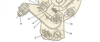
Modification of the generator
This technology for switching to a contactless ignition system is interesting because the motorcycle owner does not need to buy a new generator designed to work in an electronic ignition system. Accordingly, the cost of rework will be minimal.
Enough:
- Make a modulator that will interrupt the circuit;
- And install it on the generator (on the rotor shaft).
A metal plate with a hole drilled in it for a mounting bolt can serve as such a modulator-chopper.
Photo of the only element that you have to make yourself
The modulator installation procedure is as follows:
- The modulator plate (in the diagram below under No. 2) is installed under the mounting bolt;
- Slightly attracted to him;
- By rotating the crankshaft, set the piston to TDC;
- We set the ignition timing;
- Tighten the plate with the mounting bolt.
The electrical wiring of IZH Jupiter 5 remains unchanged when altering the generator.
For reference: in addition to the modulator, two Hall sensors are installed under the engine cover (in diagram No. 1). There are places to attach them.
Setting the appropriate options
Setting up the BSZ on Izh Jupiter 5 also requires special attention. The ignition is turned on with the tachometer connected. After thirty seconds, indicators of 3000, 4000, 5000 rpm should appear on the device panel. If they are present, then the switch is working correctly.
In other cases, you should pay attention to previously grounded candles. We insert a screwdriver into the hall connector, and then pull it out
A spark should appear on the spark plugs. If it was not possible to cause a spark using the steps described above, then the reason for the incorrect operation is incorrect connections.
The setup looks like this. The dial indicator is unscrewed and the cylinder piston is adjusted. Having connected the voltmeter to the second and third connectors, you need to start rotating the modulator axis. After a jump from 7 to 0.1 volts is detected, the modulator must be secured with a nut. Usually the required advance angle is set.
The test run should be successful if you install the components yourself according to the instructions. Now you can use BSZ.
The main problem with the Izh Jupiter motorcycle engine is the standard contact ignition system. Any owner of Jupiter sooner or later faces the problem of failure of one of the cylinders due to a change in the gap in the contacts or failure of the capacitor. Adjustment helps, but usually not for long. This problem can be radically solved by installing a contactless ignition system on a motorcycle.
Single-channel BSZ.
There are probably many options for BSZ design, but we won’t consider them all. Let's focus on the simplest, and probably the most common option in our country. There is no motorcycle market or motorcycle store nearby where you can buy a factory-made BSZ, and there is no turner with a machine nearby either. We will proceed from this.
Minimum set for installation
But we can’t do without a minimum set, so before you start work, you need to stock up on the following components, which are sold in any auto shop or car market in our country:
1. Switch from VAZ 2108
2. Hall sensor from VAZ 2108
3. Set of wires for BSZ from VAZ 2107 (from distributor (Hall sensor) to switch)
4. Two-terminal ignition coil (from an Oka or Gazelle car with a ZMZ 406 engine)
5. Two automotive silicone high-voltage wires of the required length with caps for spark plugs (you can buy a kit for a VAZ and take it from there, you can simply find used wires, after first making sure they are working)
Next, in addition to the components, we will need a small flat piece of sheet steel 1-1.2 mm thick to make a modulator and a plate for the Hall sensor. I warn you right away that stainless steel or non-ferrous metals are not suitable for the manufacture of the modulator, since they are not magnetic materials. To make a plate for the Hall sensor, you can use any material of sufficient strength.
Tools you may need are a drill with drills, files, a chisel, a hammer and other tools that, as a rule, are found in any garage.
Rework process
We dismantle the old ignition system. We remove the plate with contacts, capacitors, ignition coils with high-voltage wires from the motorcycle. We install the switch in the right glove compartment.
We attach the ignition coil to the frame under the tank. We connect the wiring connector to the switch, connect the black ground wire from the connector to ground. We connect the wire from terminal No. 1 of the switch connector to one of the coil terminals. We connect the second terminal of the coil to the old wiring, to the wire to which “+12V” is supplied when the ignition is turned on. In the old wiring, this wire connected both ignition coils. From it we pull an additional “+12V” wire to the switch, which we connect to the 4th wire in the connector. We carefully isolate everything. We insert the wire with the connector to the Hall sensor into the cavity of the generator.
You can check the functionality of the system. We connect the Hall sensor to its connector, connect the high-voltage wires to the coil and to the spark plugs. We provide reliable weight to the candles. Turn on the ignition and pass a metal object (you can use a flat screwdriver) through the Hall sensor slot. The spark plugs should spark. The scheme is working. (If there is no spark, then something is connected incorrectly and everything needs to be checked again.) Now it remains to supply a spark at the right time to the cylinders, for this:
Engine diagnostics and repair
It is sometimes impossible to find the cause of a breakdown after one visual inspection. In some cases, complete disassembly of the IZH Jupiter 5 engine is necessary. But if you find out the reason, you can quickly solve the problem yourself. Here are examples of main faults and repair recommendations:
- If your kickstarter turns on the crankshaft, you must:
- Tighten the fasteners more tightly, and in case of severe damage, replace the kickstarter shaft and lever. This usually happens after the IZ Jupiter 5 engine has been boosted.
- If the oil is selected incorrectly, especially if it is very viscous in winter, it is necessary to select a more correct temperature regime.
- If the trigger spring is weakened, it must be replaced.
- If no fuel gets into the carburetor, you should clean it in a solvent, and also blow out the channels and fuel supply hose with pressurized air.
- If there is no spark in the combustion chamber, replace the spark plug or clean it.
- When the throttle valve sticks, it is necessary to adjust its drive and clean the carburetor.
If the engine is unstable or does not start the first time, it is worth checking:
- Fuel supply system. The fuel mixture may be oversaturated with air. The solution to this problem is to replace the air filters and install new gaskets.
- Is the capacitor OK? If strong sparking occurs between the contacts, the capacitor must be replaced.
- Severe wear or burning of the spark plug. In most cases, it is the spark plugs that cause poor starting and uneven engine operation.
In cases where the motor stalls after a short period of operation:
- The drainage hole of the fuel drum should be cleaned.
- There are cases where the carburetor needle falls out. It needs to be inserted into place and adjusted.
During unstable operation under load, the following occurs:
- Cleaning and purging of carburetor channels and jets.
- Adjusting the carburetor to supply gasoline for a combustible mixture. When the quantity is large, popping noises occur in the muffler, because the mixture hits the hot metal walls and burns out there.
- If the fuel manifold drive becomes stuck, the needle must be returned to its standard position.
- In case of low cylinder compression, it is necessary to remove all carbon deposits from the piston and clean the piston rings. And in case of severe damage, completely replace the piston along with the cylinder. To prevent malfunctions, you should use only high-quality fuel and oil from trusted manufacturers.
- Ignition adjustment. With early ignition, you can hear the engine knocking, and with late ignition, popping noises in the exhaust pipe.
Engine overheating and loss of power occur for the following reasons: Driving in the heat at low gearbox levels during a long trip. It is worth stopping periodically and letting the engine cool. Insufficient amount of oil in the fuel mixture. Heavy carbon deposits on the cylinder and piston walls. As mentioned earlier, for prevention it is worth cleaning the engine as often as possible.
These are the main problems that may occur during operation. How to disassemble the IZ Jupiter 5 engine is written in detail in the maintenance book issued upon purchase. Everything stated in it is written in clear text, with diagrams and detailed instructions. Not only the repair of a Soviet unit is within the power of any owner.
There are many questions about how to assemble the IZH Jupiter 5 engine yourself, modifying it. For example, installing a more reliable carburetor or a more stylish and loud muffler can be done quickly enough without significant financial investments.
Tuning an IZH Jupiter engine with your own hands is possible if you have enough time and enthusiasm. You just need to be persistent.
The motorcycle has a favorable ratio of cost, build quality and maintenance requirements. An ideal option for people with a small budget and those who want to get universal equipment. However, frequent breakdowns will take a lot of time. It's worth being prepared for this, since some bikes can be 40-50 years old.
Maintenance
The owner can independently perform some maintenance procedures:
- check the motorcycle generator if the battery loses charge;
- set the gap between the breaker contacts;
- adjust the quality of the sound signal.
The need to inspect and adjust the wiring arises if:
- the motorcycle moves in the rain for a long time, as this causes oxidation of the contacts;
- a motorcyclist rides in an area with a lot of vegetation that damages wiring;
- The driver rides in snow in winter, which can stick to electrical wiring parts and damage them.
Self-check of the Planet 5 motorcycle generator in case of loss of charge
The cause of loss of charge in the IZH Planet 5 battery is most often a breakdown of the generator.
To check it yourself you need:
- multimeter device;
- straight screwdriver.
Step-by-step instruction
The following steps must be followed:
- Disconnect the wires from the battery and remove the generator cover.
- Disconnect the top 5 wires from the generator, first unscrewing their fastenings. In order not to mix up the wires during assembly, it is worth marking them.
- Measure the winding resistance using a multimeter in ohmmeter mode. To do this, you need to touch the body with one probe, and the other should be connected in turn to the 3 wires of the winding. There should be no short circuits, as indicated by the inscription on the multimeter screen.
- Test the resistance between the stator contacts: you need to touch them one by one with the multimeter probes. The value on the screen should be 8 ohms.
The presence of a short circuit in the 3rd stage or a discrepancy in the indicators in the 4th will indicate problems with the generator.
Photo gallery: stages of checking the IZH Planet 5 generator in case of loss of charge in pictures
How to correctly set the gap between the contacts of the breaker?
In order to set the gap between the breaker contacts, you will need:
- straight screwdriver;
- wrench 10;
- candle key;
- probe 0.4 mm thick (+/– 0.05 mm).
Next, you need to follow the steps sequentially:
- Place the motorcycle on a stand and place the gearbox in neutral.
- Remove the right crankcase cover and unscrew the spark plug.
- Using a 10mm wrench, grab the generator rotor mounting bolt and turn the crankshaft to a position where the contacts are as far apart as possible.
- Loosen the screw securing the contact.
- Place the probe between the contacts and adjust the tightening of the eccentric screw until the probe passes the contacts with little resistance.
- Tighten the contact fixing screw.
Photo gallery: adjusting the gap between the breaker contacts
Troubleshooting the audio signal and improving signal quality
Poor sound signal quality is mainly caused by improper adjustment.
The following tools will be needed for setup:
- wrench 7;
- a simple screwdriver.
Step-by-step instruction
To adjust, do the following:
- Loosen the locknut with a wrench.
- Turn on the ignition.
- Press the button to turn on the sound signal.
- Adjust the sound by rotating the adjusting screw.
- When the desired result is achieved, tighten the locknut.
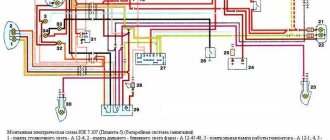
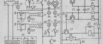
Electrical circuits of the ignition systems of the IZH Jupiter 5 motorcycle
1 - parking light lamp - A 12-4; 2 - high beam - low beam headlight - A 12-45:40; 3 - indicator lamp for generator operation - A 12-1; 4, 5 — speedometer scale illumination lamps — AMN 12-3; 6, 16, 17, 20, 23, 30 — lamps for the direction indicators of the motorcycle and side trailer; 7 - combination switch (right switch); 8 — brake light switch for the front wheel brake; 9 - breaker; 10 — spark plug; 11 — ignition coil; 12 - generator; 13 — rectifier-voltage regulator BPV14-10; 14 — brake light switch for the wheel brake; 15, 19 — side trailer clearance lamps — A 12-5; 18 — brake light lamp for side trailer — A 12-21-3; 21 — motorcycle brake light lamp — A 12-21-3; 22 — motorcycle rear marker lamp — A 12-5; 24 - battery; 25 - fuse; 26 — neutral lamp switch; 27 — ignition switch; 28 — sound signal; 29 — alarm switch (left switch); 31 — turn signal switch; 32 - high beam headlight control lamp - A 12-1; 32 — control lamp “neutral” — A 12-1; 33 - control lamp for direction indicator lights - AMN 12-3; Symbols on the BPV14-10 block (items 12,13): XI - “-” excitation windings; X2 - “-” battery (“ground”); ХЗ - “+” output to the control lamp; X4, X5, X7 - phases of the stator winding of the generator; X8 - “+” of the battery.
Video “Installing BSZ on IZ Jupiter 5”
This video talks about installing a contactless ignition system on a Jupiter 5 motorcycle (the author of the video is Andrey).
I have in my garage my “Old Friend” IZH Yu-5, which was given to me when I graduated from school! The only owner of which is only me. I haven’t driven it for a long time, more than 10 years, and it wouldn’t start, there was no charging, constant problems with the cams and dead ignition coils, and of course the right pot! It's time to resuscitate my friend! It was decided to install the BSZ, do normal charging with car elements and replace the wiring! I go to the store and buy parts:
1. Relay – regulator 2101, 2106.2. Generator diode bridge (suitable for VAZ and GAZ generators. 3. Capacitor for diode bridges (in my opinion, they are all the same for VAZ and GAZ) 4. 2 spark plugs from GAZ with an electronic ignition system. 5. 2 short high-voltage silicone wires (I bought them for fifty dollars in some garage cop)6. Ignition coil (VAZ 1111, GAZ with engine 406) two-terminal, dry.7. Switch (VAZ 2108)8. Hall sensor (VAZ 2108)9. Connecting blocks for the switch and Hall sensor.10 . Emergency ignition. (just in case) 11. Terminals, wires, electrical tape and nut - I think everyone has them in the garage 12. I ordered a modulator plate and a hall sensor mounting plate on the Internet, so I could sharpen it myself into scrap))
Installing the BSZ1. Remove the breaker contacts, coil, capacitor and all the other crap from contact ignition. 2. Put the switch in the right glove compartment, the coil under the tank. 3. Unscrew the generator bolt. 4. Install the modulator. 5. Attach the Hall sensor. 5.1. We fasten the modulator, but do not tighten it! 6. Connect everything according to the following diagram. Save to Album Scheme 1 Scheme 1
7. We put the armor wire on the candle, connect it to the coil. Everything is done according to the first scheme, everything is done in an elementary way and in time you can manage it in an hour with smoke breaks.8. Connect the ignition coil. Save to Album Diagram 2 color Diagram 2 color
The ignition is set simply: the piston is at TDC further 3.5 mm back and for the convenience of finding the moment of the spark, an instant diagnostic unit “MD-1” was purchased
Next we start charging1. We throw out all the elements of the old charging system2. Brushes. Since the relay-regulator used controls the current on the rotor through (+), you need to do the following. Plastic blocks are installed on the generator housing, which allow you to isolate the wire connections from the housing. We find the connection between the white brush wire and the short wire with the black wire and release the brush wire (unscrew the nut on M3). There is a 3mm terminal mounted on it, we drill it out to 4mm. And now we put this terminal on the mounting screws of the block itself and tighten it, thereby feeding it to the brush (-). 3. Diode bridge. On the BPV, black wires (-) go to the lower left part of the BPV and red wires (+) to the middle lower part of the BPV. And three pink ones on the right side of the GSV. We release the black ones and twist them, and we do the same with the red ones. And we remove the pink ones (they come from the generator from each phase and supply alternating current from each phase, of which there are only three) and leave them as is. The diode bridge consists of two plates, one of them is (+), the other (-) and they are insulated from each other, the plate that has insulation on the mounting hole (at the end) is (+). We connect the red wires (+) to plate. And we connect the black and brown ones to ground (-). The diode bridge is connected. 4. Relay regulator. Take (+) anywhere after the ignition key. This terminal will go to the groove size No. 15. We take the wire (+) of the brush, it was removed from the lower right part of the BPV, this is the wire for terminal size No. 67. We take the solution and connect it. Next, we screw the solution to ground; you can’t start it without this, otherwise it will burn out! 5. To make sure the charging light on the dash goes out, put it through the relay.
The main visual difference between the two motorcycles of the IZh family is the number of engine cylinders. The Jupiter 5 model has two of them, while the Planet 5 has only one.
In all other respects, the models are maximally unified with each other, with the exception of electrical components.
Contactless electronic ignition on the legend of the domestic motorcycle industry - IZH Jupiter 5
IZH motorcycles are rightfully considered legends of the domestic automotive industry. The use of these vehicles was especially important in the Soviet years, however, even today ILs are successfully used by many domestic motorists. In this article we will talk about what electronic ignition is on the IZ Jupiter 5 motorcycle and how the ignition system (IZ) is configured.
Tuned motorcycle IZH Jupiter 5
IZ Jupiter 3 uses non-contact ignition (BSZ) 1137.3734, intended for all models equipped with a 12-volt generator. The ignition coil module for Jupiter 4 or another model makes it possible to select the appropriate operating mode of the motor thanks to the serial connection of the output wires.
The device as a whole improves the technical parameters of the vehicle thanks to:
- improved engine starting at low temperatures;
- more stable operation of the power unit, which is achieved as a result of reducing the asynchrony of spark formation, as well as by optimizing the SZ advance angle in accordance with engine speed;
- reducing the level of toxicity of exhaust gases, fuel consumption, as well as reducing deposits on spark plugs;
- stable start of the power unit even on a battery that has run down to 6 volts, provided that certain models of ignition coils are used;
- easier installation and maintenance of the system as a whole.
Technical data
Operation of a contactless SZ on Jupiter
Let us briefly consider the main technical parameters characteristic of the third IL model:
- The negative terminal of the battery is always grounded, the battery voltage level is 12 volts.
- If the ignition switch is turned off, and therefore the engine does not work, the current consumption parameter will be no more than 0.15 amperes.
- The unit allows for uninterrupted spark generation if the number of crankshaft revolutions does not exceed 7 thousand per minute. The level of current consumed by the node in this case will be no more than 2.5 amperes.
- In addition, the mechanism also allows for uninterrupted spark formation if the voltage parameter in the electrical circuit changes from 6 to 16 volts. At this time, the voltage indicator on the spark plugs will not change.
- According to technical data, the unit can function normally if the air temperature is from 25 degrees below zero to 60 degrees above zero.
- Thanks to the use of a microprocessor component in the operation of the unit, torque generation allows for the correct and stable operation of all other mechanisms. Of course, if the power unit is operating in normal mode.
Scheme
Ignition circuit for an IZH motorcycle
As for the circuit, the optical ignition on the IZH Jupiter 5 or any other SZ is mounted using spare parts and fastening components that are included in the kit. As you know, the mechanism is designed to ignite the air-fuel mixture. The mixture itself, which is located in the engine cylinder, ignites thanks to a spark formed between the electrodes of the spark plug. It's no secret that the quality of the functioning of the safety system largely affects the operation of the entire vehicle.
As practice shows, one of the problems of IZhs is that the advance angle periodically gets lost. This is due to wear on the cams, as well as the contacts of the interrupter device. It should be noted that mechanical influences in electronic SZ are completely absent.
The pulse is removed in a separate block, and the signal goes to the switch, where it is amplified. Subsequently, the pulse arrives at the coil, then everything happens as usual. A discharge is applied to the spark plug, which causes the mixture to ignite, causing the crankshaft to start moving. Replacing a device or adjusting it at home is not so difficult, but you need to remember that incorrect actions can lead to possible malfunctions in the future.
To configure the system on a motorcycle, it is advisable to use devices with a scale of up to 15 volts and an internal resistance of up to 0 kOhm. Thanks to the electronic device, adjusting the unit will not take much time and effort. The terminals from the device must be connected to the Hall sensor. The procedure for setting up contact ignition without using auxiliary devices is shown in more detail in the video below (the author of the video is the Han Rulyu channel).
So, for proper tuning, place the cylinder piston in a position that provides the most optimal spark formation. Any cylinder can be used. Then the ignition is activated, and the modulator device must be turned in the direction of movement of the rotor with the crankshaft. Rotation is carried out until changes are visible on the voltmeter screen. At the moment when you can catch a spark, the position of the curtains should not be changed. As for the modulator device, it must be securely fastened to the generator shaft; a fastening screw is used for this.
During setup, you should in any case short-circuit the high-voltage circuits to the motor housing. This is done so that when using a short circuit, the system does not overload, which can ultimately lead to failure of the BSZ. In addition, the engine cannot be stopped when removing the spark plug caps.
After the adjustment is made, the performance of the system must be checked. If you place the cable being tested approximately 7-8 mm from the power unit and then try to start the engine, a spark should jump out. As you can see, in general, the procedure for setting up a node is not particularly complicated, but it requires care and the right approach, so the above recommendations are still worth considering. In addition, one should not forget about safety precautions, since incorrect actions can lead to a short circuit in the wiring and failure of the unit as a whole.
Video “Instructions for setting up the ignition on the IZH Jupiter 5 motorcycle”
You can learn how to correctly carry out this task at home from the video below, where this procedure is described in detail (by Kirilldo911).
AvtoZam.com
System assembly and installation
The contacts in the breaker, the capacitor, the ignition bobbins and the armor wires, which are part of the previous ignition device, are probably eliminated. The switch should be installed in the glove compartment on the right, and the ignition coil directly under the tank. There are no gaps for fastening on the reel, which means it can be attached using a thick layer of adhesive tape. The standard bolt is also eliminated along with other parts.
In place of the bolt, install a pin of the specified size and put on a washer. Then, the rotor is tightened with a nut located at its end. The hall sensor is attached to the stator by any means. The basic rule when installing it is to set the optimal cross-sectional distance of the modulator and the ratio of the radius and line of symmetry.
When the hall sensor can be secured, we apply the modulator. It should fit into the hole made in the sensor. In most situations, there is a discrepancy between the sizes, so it is necessary to place washers on the stud. If you manage to maintain the required gap, it is recommended to install an engraver and tighten the modulator with a third-party nut.
Installation of BSZ on Izh Jupiter-5: advantages of the system
08.05.2017
Installing a contactless ignition system on Izh Jupiter-5 is a fairly current topic. When setting up a BSZ on Izh Jupiter-5 BSZ, it is necessary to take into account a number of nuances that can significantly affect the operation of the equipment used.
What advantages open up to users who decide to install electronic ignition on the Izh Jupiter are described below.
Most modern motorcycles are not equipped with cams, that is, breakers. Why did the manufacturer consider them unnecessary for currently sold models? The answer is quite simple. This system is not very reliable.
Many parts used in the system are sources of trouble. The most common ones are listed below:
- The ignition gaps change their original position while driving a few days after adjustment;
- A spark occurs every once in a while, since the contacts regularly burn out;
- Capacitors are constantly damaged;
- Low spark power;
- If you add two or three volts to the battery, it is quite difficult to start it. Such ignition is the reason for constant repairs while driving.
Many people mistakenly believe that it is very difficult to implement BSZ Sovek on Izh Jupiter 5. As a rule, it takes more time to purchase the necessary spare parts than to install the BSZ on Izh. Of course, after implantation, performance changes significantly in the best direction.
This is noticeable at idle. The speed of their passage has noticeably increased and the unnatural twitching has disappeared. The characteristic knocking sounds of iron components in the crankcase and accompanying detonations also disappeared. The handling of the Jupiter 5 motorcycle will improve simultaneously with the time it takes to gain speed.
Required Parts
In order for the ignition system to work correctly, a number of auxiliary parts are required. They are listed below:
- Switch for BSZ VAZ cars. You should not choose exclusively from the low price segment. The Astro switch has a lot of positive reviews;
- Hall Sensor. The best option for Jupiter 5 is a similar manufacturer VAZ. By purchasing it in branded packaging, you protect yourself from counterfeits;
- Ignition coil with two terminals. You should choose between the gazelle engine number 406 or Oka with an electronic ignition system;
- A pair of silicone armor wires with rubber caps;
- The modulator is a butterfly-shaped plate made of iron.
Modulator
The most difficult stage is the production of the modulator. It is important to maintain the required shape. The more accurately the required dimensions are observed, the lower the likelihood of problems occurring after the system is implemented, that is, there will be no need to adjust it with a file. The ignition timing must match on any cylinder used.
The bolt hole must be located in the middle. Otherwise, the engine operation will not be synchronized. It is also recommended to check the integrity of the crankshaft bearings. If you find defects, you should immediately replace it.
The contact ignition is not able to work normally if the bearings are damaged. The thickness of the part should not exceed one and a half millimeters. If it is thin, it will not be possible to avoid deformation, and if it is thick, it will come into contact with the surface of the hall sensor housing.
To create the plate, it is allowed to use any material except steel. Aluminum and others should not be used as they are not magnetic. The drawing that must be followed can be found in the public domain. The presented diagram will be useful to those people who decide to modernize the vehicle ignition device. Below are methods for installing electrical ignition devices in Jupiter.
It must be turned by a professional turner. He will make a simple disk and draw on it the markings of elementary distances between the corners. Then, in accordance with it, you will cut out the necessary sectors at home. The cost of the modulator is seventy rubles.
It is not advisable to use an ordinary plate, since its width is less than twelve millimeters. This will not be enough to fully accumulate the energy resource in the coil. Of course, it can be installed, but achieving four thousand revolutions per minute will become impossible.
In addition to the above you will need:
- A stud with an applied thread of seven millimeters, pitch 1, as well as a pair of nuts with washers of the corresponding parameters.
The priority material for these components is brass. This is explained by the least magnetization of the plate from the generator rotor. If you use a standard bolt, then difficulties may arise with the implementation of the ignition. The bolt tends to follow the modulator as it is tightened. However, it is necessary to observe the leading indicator, maintain the same position of the rotor and modulator, and tighten the bolt. It is advisable to use a pin, since many are not able to perform all the necessary actions in total; - A set of wires with connectors for ignition without contact from VAZ. This part can be purchased or made with your own hands.
System assembly and installation
The contacts in the breaker, the capacitor, the ignition bobbins and the armor wires, which are part of the previous ignition device, are probably eliminated. The switch should be installed in the glove compartment on the right, and the ignition coil directly under the tank. There are no gaps for fastening on the reel, which means it can be attached using a thick layer of adhesive tape. The standard bolt is also eliminated along with other parts.
In place of the bolt, install a pin of the specified size and put on a washer. Then, the rotor is tightened with a nut located at its end. The hall sensor is attached to the stator by any means. The basic rule when installing it is to set the optimal cross-sectional distance of the modulator and the ratio of the radius and line of symmetry.
When the hall sensor can be secured, we apply the modulator. It should fit into the hole made in the sensor. In most situations, there is a discrepancy between the sizes, so it is necessary to place washers on the stud. If you manage to maintain the required gap, it is recommended to install an engraver and tighten the modulator with a third-party nut.
Final actions
You should put rubber caps on the armor wires, and insert the latter into the candlesticks or coil above. If you skip this step, the motorcycle will stall when riding in rainy weather, as moisture will get into the battery.
By inserting spark plugs into the tip, it will be possible to maintain excellent contact between the battery and the volume of the vehicle. Now you will need a pre-purchased set of wires. The switch, coil and hall sensor are connected by wiring. She needs to be isolated. Of the entire mass, only a common plus is required.
Setting the appropriate options
Setting up the BSZ on Izh Jupiter 5 also requires special attention. The ignition is turned on with the tachometer connected. After thirty seconds, indicators of 3000, 4000, 5000 rpm should appear on the device panel. If they are present, then the switch is working correctly.
In other cases, you should pay attention to previously grounded candles. We insert a screwdriver into the hall connector and then pull it out. A spark should appear on the spark plugs.
If it was not possible to cause a spark using the steps described above, then the reason for the incorrect operation is incorrect connections.
The setup looks like this. The dial indicator is unscrewed and the cylinder piston is adjusted. Having connected the voltmeter to the second and third connectors, you need to start rotating the modulator axis. After a jump from 7 to 0.1 volts is detected, the modulator must be secured with a nut. Usually the required advance angle is set.
The test run should be successful if you install the components yourself according to the instructions. Now you can use BSZ.
motoznai.ru
Improving the standard system
The ignition system can be improved in other ways. To do this, you need to identify what problems there are with the wiring. They can occur in the primary circuit between the coil and the 12V battery or due to operating conditions. A visual inspection of the primary circuit can reveal problems with connections, contacts and the ignition switch.
But when dirt and dust get into the circuit, the resistance at the contact points increases, which entails a decrease in voltage from 12 Volts to 7-8 Volts. This voltage is not enough for a powerful discharge to appear in the secondary winding of the coil. As a result, a charge of less than 12 V appears on the spark plug, which poorly ignites the combustible mixture in the cylinders. Burnt contacts, oily spark plugs and batteries with a charge of less than 12 V further worsen sparking.
Standard wiring after modification
The following measures help solve these problems:
- The plug connectors are removed and each wire is soldered using traditional soldering and then insulated.
- An additional toggle switch is installed that turns off all consumers when the engine starts. Thus, the coils are supplied with 12 volt voltage from the battery (diagram 1).
- Remake the ignition switch (IZ) (diagram 2). You need to take a wire and solder one end of it to the connector of lock 4, which is free, and the other to the positive terminal of the coil. The standard wire should be re-soldered from terminal 5 to terminal 6. After turning on this position of the key, power is supplied from the battery to the primary circuit according to a simplified scheme.
Loading …
IZH Jupiter 5 and its electrical equipment: briefly about the main thing
Unlike similar Soviet-era motorcycle models, the electrical wiring diagram of the IZH Jupiter 5 motorcycle provides for operation from a battery with air-cooled equipment. This causes many problems for owners. The article provides recommendations for modernization that solves problems with sparking.
Models of IZH motorcycles are as unified as possible. The wiring diagram for IZ Jupiter 2 is not much different from later versions of the IZ motorcycle. There are external differences. For example, the Planet 5 bike has one cylinder, and the Jupiter 5 has two.
The first 12-volt motorcycle was the IZH Jupiter 4. The wiring diagram for the IZH Jupiter 5 and the wiring diagram for the IZH Jupiter 3 differ in components.
Wiring diagram IZ Jupiter 5
The bike of the fifth Jupiter has a contact SZ, which is powered by a battery, so the operation of the vehicle is highly dependent on the state of charge of the battery.
If charging is insufficient, the following problems occur:
- the motor runs intermittently;
- the engine starts with difficulty;
- At low speed the battery is discharged.
These problems can be eliminated by switching to BSZ. Any electrician can handle this task (the author of the video is Viter Electronic).
How to make the transition to contactless SZ?
To switch to contactless SZ, motorcyclists use parts from other motorcycle models. When upgrading the generator set, the wiring of the IZH Jupiter 5 remains unchanged. Minor alterations concern the electrical circuit of the IZH. After changes, the battery is used to service auxiliary equipment. To switch to BSZ, parts are taken from Planet 5 and the VAZ 2108 car.
The following changes are being made to the electrical circuit of IZH:
- install 2 Hall sensors from the eighth VAZ model;
- 2 VAZ electronic switches must be connected to the sensors;
- each of the cylinders serves a commutator-sensor pair;
- You need to add two more ignition coils to the circuit.
SZ after modernization
On the electrical circuit of the IZH motorcycle, the components are marked with numbers:
- Spark plug.
- Ignition coils from Planet 5.
- Switches.
- Hall sensors.
- Egnition lock.
- Battery.
For the created ignition system, it is necessary to modify the IZ Jupiter 5 generator, the circuit of which will not require major changes.
How can I modify the generator?
The presented modernization option is advantageous in that it does not require the purchase of a new generator that will service the new ignition system.
Recycled generator design
All you need to do is follow these steps:
- make a modulator-breaker of an electrical circuit;
- install a breaker on the rotor shaft or generator.
You can create a modulator with your own hands. To do this, you need to take a metal plate and drill a hole in it for the fastening bolt. The manufactured part will serve as a modulator-chopper.
Homemade modulator for interruption
The modulator is connected as follows:
- install the modulator plate (2) and tighten it with the bolt (3), but not all the way;
- by rotating the crankshaft, you need to ensure that the piston is at top dead center;
- Next you need to set the ignition timing;
- Now you can tighten the mounting bolt on the plate.
Hall sensors (1) are installed together with the modulator.
Improving the standard system
The ignition system can be improved in other ways. To do this, you need to identify what problems there are with the wiring. They can occur in the primary circuit between the coil and the 12V battery or due to operating conditions. A visual inspection of the primary circuit can reveal problems with connections, contacts and the ignition switch.
If operating conditions are ideal, the primary circuit will operate with a 12V battery without failure.
But when dirt and dust get into the circuit, the resistance at the contact points increases, which entails a decrease in voltage from 12 Volts to 7-8 Volts. This voltage is not enough for a powerful discharge to appear in the secondary winding of the coil. As a result, a charge of less than 12 V appears on the spark plug, which poorly ignites the combustible mixture in the cylinders. Burnt contacts, oily spark plugs and batteries with a charge of less than 12 V further worsen sparking.
Standard wiring after modification
The following measures help solve these problems:
- The plug connectors are removed and each wire is soldered using traditional soldering and then insulated.
- An additional toggle switch is installed that turns off all consumers when the engine starts. Thus, the coils are supplied with 12 volt voltage from the battery (diagram 1).
- Remake the ignition switch (IZ) (diagram 2). You need to take a wire and solder one end of it to the connector of lock 4, which is free, and the other to the positive terminal of the coil. The standard wire should be re-soldered from terminal 5 to terminal 6. After turning on this position of the key, power is supplied from the battery to the primary circuit according to a simplified scheme.
Thus, the changes made will make the electrical wiring of the IZH Jupiter 5 motorcycle more reliable and efficient.
Video “Installing BSZ on IZ Jupiter 5”
This video talks about installing a contactless ignition system on a Jupiter 5 motorcycle (the author of the video is Andrey).
AvtoZam.com