Cars admin26.02.2020
The wiring diagram of IZH Planet 5 has a simple design: a single-wire DC network is provided by a 12-volt battery, which is charged by a generator with a power of 100–140 watts. The role of the negative wire in the electrical circuit is played by the metal frame, and since the rest of the wiring has a positive charge, their short circuit is often the main cause of the malfunction.
Electrical equipment IZH Planet 5
Video: review of IZH Planet 5 wiring
Headlight and dashboard lamps
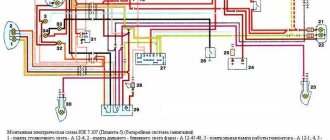
Wiring diagram IZH Planet 5
Explanations for the diagram
Self-check of the Planet 5 motorcycle generator in case of loss of charge
How to correctly set the gap between the contacts of the breaker?
Troubleshooting the audio signal and improving signal quality
Video: installation of electrical wiring on IZH Planet 5 with description
Comments and Reviews
If there is no charging on the Izh Jupiter motorcycle.
This article was written to help those motorists who decided to find and fix a malfunction in the battery charging system on IZH 12V motorcycles themselves.
Of the special instruments, you will need the simplest tester with a continuity function (tweeter) and resistance measurement. If you do not have this device, then you can use a light bulb with a battery to determine the contact or break in the circuit.
In this case, you need to install a well-charged battery on the motorcycle, or power the on-board network from another external power source with a constant voltage of 12 V. First of all, we check the presence of voltage with the ignition switch on at the positive terminal of the regulator relay. There should be +12v.
If there is no voltage, then we look for a break from the positive terminal of the battery through the ignition switch and to the + terminal on the relay regulator.
Next, we measure the voltage on the brushes. There should be +12V on one of the brushes. If not, we call the wiring from the relay to the generator brushes.
Next step. We take the brushes out of the holder and ring each of them from the terminal to the graphite. It happens that at the point of contact of the wire with the graphite body of the brush itself, the contact is lost.
Troubleshooting the generator
Three phase wires are disconnected from the stator and the winding (connected to each other according to a star circuit) is connected. That is, the windings should ring with each other and have approximately the same resistance. If some winding does not ring, this means that there is a break and the stator is not working properly.
Next, all three phases are called relative to the body (mass). If it rings, it means the windings are broken into the housing and the stator is not working properly.
Anchor
We ring the armature winding (on copper rings). If the rings ring among themselves - good, if not - there is a break, the armature is not working.
The next step is to wire the armature winding relative to the armature body.
If it doesn’t ring, it’s good; if it rings, the winding is broken into the housing and the armature is not working properly!
Relay regulator
If all the wiring is in order, the brushes, stator and rotor are ringing and everything is working, all that remains is the relay regulator! In my experience, even if you don’t have much knowledge of radio electronics, you can at least remove the back cover of the relay regulator and wipe off all the dirt. Carefully look at all the contacts, fastening parts, wires, jumpers; sometimes the contact or soldering simply falls off due to vibration. The diode bridge is practically “eternal”. But the control thyristors sometimes fly out! They are also called simply - to check for breakdown on the housing and between the cathode and the control electrode!
They are also easy to change; a 10 mm nut is unscrewed from below and the wires are unsoldered from above.
That's basically it. And there is absolutely no need to change entire components at random; there can be a lot of reasons, even banal bad contact on the chips or oxidation of the wires in the connector
The editors of the magazine thank Sergei Sharikov for kindly providing materials for the article.
If you have something to share with readers and would like to publish your story or photo report about your travels on our website, please send the materials to:
Source
Improving the standard system
For those owners who do not want to switch to a contactless ignition system, there are other ways to improve sparking.
At the same time, the wiring of the IZH Jupiter 5 motorcycle is analyzed for problem areas, and most often:
- The primary circuit from the battery to the coil is diagnosed;
- Locations of voltage reduction caused by operating conditions are identified.
A simple inspection of the primary circuit will demonstrate several problem areas at once:
- four plug connectors;
- emergency ignition switch;
- central switch contacts;
- breaker contacts.
Under ideal operating conditions, such a complex section of the chain will work flawlessly.
But in practice, it is exposed to dust and dirt flying from under the wheels, so in the circuit due to the increase in resistance at the contact points:
- the voltage decreases from 12 V to 7-8 V;
- this is not enough to excite a powerful discharge in the secondary winding of the coil;
- as a result, a low discharge on the spark plug, making it difficult to ignite the combustible mixture in the cylinders.
And if you add to this a dead battery and oily spark plugs with burnt contacts, then the sparking process becomes completely problematic.
Motorcyclists solve such defects as follows:
- traditional soldering. The wiring on IZH Yu5 gets rid of plug connections and each wiring is soldered manually, followed by insulation;
- installation of an additional toggle switch (in diagram No. 1), which turns off all consumers at the moment the engine starts. This allows the maximum voltage from the battery to be supplied to the coil;
- alteration of the ignition switch. A wire is soldered to the free connector of lock 4 (in diagram No. 2), the second end of which is fed to the positive terminal of the coil. The standard ignition wire from terminal 5 is transferred to terminal 6 and when this key position is activated, a simplified power supply circuit from the battery to the primary circuit of the coil is activated.
Conclusions: from this article you can learn not only proven methods for improving the electrical part of a motorcycle (as in the article about), but also watch video materials that clearly demonstrate the algorithm for modernization work.
Unlike similar Soviet-era motorcycle models, the electrical wiring diagram of the IZH Jupiter 5 motorcycle provides for operation from a battery with air-cooled equipment. This causes many problems for owners. The article provides recommendations for modernization that solves problems with sparking.
[Hide]
Communities › Around the Wheel (motorcycles, ATV, jet skis) › Blog › BSZ and R-R with a road bridge on IZH Yu-5
I have in my garage my “Old Friend” IZH Yu-5, which was given to me when I graduated from school! The only owner of which is only me. I haven’t driven it for a long time, more than 10 years, and it wouldn’t start, there was no charging, constant problems with the cams and dead ignition coils, and of course the right pot! It's time to revive your comrade! It was decided to install the BSZ, do normal charging with car elements and replace the wiring! I go to the store and buy parts: 1. Relay - regulator 2101, 2106. 2. Diode bridge of the generator (suitable for VAZ and GAZ generators. 3. Capacitor for diode bridges (in my opinion, they are all the same for VAZ and GAZ) 4. 2 spark plugs from GAZ with an electronic ignition system. 5. 2 short high-voltage silicone wires (I bought it for fifty dollars in some garage cop) 6. Ignition coil (VAZ 1111, GAZ with engine 406) two-terminal, dry. 7. Switch (VAZ 2108) 8. Hall sensor (VAZ 2108) 9. Connecting blocks for the switch and the Hall sensor 10. Emergency ignition (just in case) 11. Terminals, wires, electrical tape and nut - I think everyone has them in the garage 12. Ordered a modulator plate and a fastening plate The hall sensor on the internet was scrapped by myself))
Installing the BSZ 1. Remove the breaker contacts, coil, capacitor and all other crap from the contact ignition. 2. We put the switch in the right glove compartment, the coil under the tank. 3. Unscrew the generator bolt. 4. Install the modulator. 5.Attach the Hall sensor. 5.1. We fasten the modulator, but do not tighten it! 6.We connect everything according to the following scheme. Save to Album Diagram 1 Diagram 1
7. We put the armor wire on the spark plug and connect it to the coil. Everything is done according to the first scheme, everything is done in an elementary way and in terms of time you can do it in an hour with smoke breaks. 8. Connect the ignition coil. Save to Album 2 color scheme 2 color scheme
The ignition is set simply: the piston is at TDC further 3.5 mm back and for the convenience of finding the moment of the spark, an instant diagnostic unit “MD-1” was purchased
Next, we are engaged in charging 1. We throw out all the elements of the old charging system 2. Brushes. Since the relay-regulator used controls the current on the rotor through (+), you need to do the following. Plastic blocks are installed on the generator housing, which allow you to isolate the wire connections from the housing. We find the connection between the white brush wire and the short wire with the black wire and release the brush wire (unscrew the nut on M3). There is a 3mm terminal mounted on it, we drill it out to 4mm. And now we put this terminal on the mounting screws of the block itself and tighten it, thereby applying it to the brush (-). 3. Diode bridge. On the BPV, black wires (-) go to the lower left part of the BPV and red wires (+) to the middle lower part of the BPV. And three pink ones on the right side of the GSV. We release the black ones and twist them, and we do the same with the red ones. And we remove the pink ones (they come from the generator from each phase and supply alternating current from each phase, of which there are only three) and leave them as is. The diode bridge consists of two plates, one of them is (+), the other (-) and they are insulated from each other, the plate that has insulation on the mounting hole (at the end) is (+). We connect the red wires (+) to plate. And we connect the black and brown ones to ground (-). The diode bridge is connected. 4. Relay regulator. Take (+) anywhere after the ignition key. This terminal will go to the groove size No. 15. We take the wire (+) of the brush, it was removed from the lower right part of the BPV, this is the wire for terminal size No. 67. We take the solution and connect it. Next, we screw the solution to ground; you can’t start it without this, otherwise it will burn out! 5. To make sure the charging light on the dashboard goes out, run it through the relay.
Army and weapons
I have been repeatedly asked to share my experience in installing a BSZ, a diode bridge and a relay regulator. I did this as much as possible, until they began to insist that I break out in an article where I could explain everything in an accessible way. The whole difficulty lies in the fact that after these installations I long ago moved towards reworking the Izh-Yunker electrical circuit. And today, reproducing exactly how it actually was on a motorcycle is quite problematic, and even more so since the wire connection points and their colors on any electrical circuits differ from the factory ones, including the fact that I encountered the fact that on different motorcycles (Izh - Juncker) the same wires are different in color.. Therefore, I will not tell you the specific color of the wire and tie it to the diagram, but I will name the wires according to their functionality, for example: “this wire goes to the left rear marker,” and you you will have to recognize it in practice, which, by the way, is very useful for experience. I won’t describe the advantages of this or that device or the advantages of this or that method, everyone chooses shoes according to their feet, I’ll just try to present them in a way that is simple and understandable.Required spare parts and materials:
- Relay – regulator 2101, 2106.
- Generator diode bridge (suitable for VAZ and GAZ generators.
- Capacitor for diode bridges (in my opinion, all are the same for VAZ and GAZ)
- 2 spark plugs from GAZ with electronic ignition system.
- 2 short high-voltage silicone wires (I bought them for fifty dollars from some garage cop)
- The ignition coil (VAZ 1111, GAZ with engine 406) is two-terminal, dry.
- Switch (VAZ 2108)
- Hall sensor (VAZ 2108)
- Connection blocks for switch and Hall sensor.
- Heat-shrinkable cambric 8 - 2 meters.
- Set of male-female and ring terminals.
- Installation wire 1.5 square - 2.3 meters.
- In addition to the standard tool, you will need a radio crimp (you can try using pliers).
- Metal scissors.
- Sheet metal 0.8-1 mm thick 10x10 cm (I used regular galvanized steel 0.7 mm, but many recommend transformer steel, in my opinion, the higher the magnetic properties of the metal, the better, for example, case steel gave me a disgusting spark)
- Screws and nuts M3 and M4.
1. This is, of course, dismantling the standard system.
A. For relay regulator:
The battery charge control system includes a standard BPV and what I would call a generator rotor. From the BPV, 2 wires supply voltage to the rotor through the carbon brushes. One brush wire (-) is connected to the top of the BPV and it should be black. The second wire should be red (+) connected on the lower right side of the BPV. Feel free to take them off. Now you have to bend over to the generator. Since the relay-regulator used controls the current on the rotor through (+), I do the following manipulations. Plastic blocks are installed on the generator housing, which allow you to isolate the wire connections from the housing - “b”. We find the connection between the white brush wire and the short wire with the black wire and release the brush wire (we unscrew the nut on M3, if I’m not mistaken, with a key on 5). There is a 3mm terminal mounted on it, I drill it out (ordinarily with the tip of a knife) to 4mm. And now I put this terminal on the mounting screws of the block itself and tighten it,
thereby applying (-) – “a” to the brush. By this action I get 2 advantages, 1 – I free one wire in the harness from the top of the wiring to the generator (it is enclosed in a black cambric), 2 – I reduce the resistance in the rr-rotor circuit, albeit slightly, but I reduce it. In my opinion, with such a generator, every half of a tenth of a volt is relevant, the economy should be economical.
b. For a diode bridge from VAZ, GAZ:
Easier than steamed turnips. On the BPV there are black (some have brown and God knows what other color it might be) wires (-) on the lower left part of the BPV and red (and there may also be one light blue, dark blue, etc.) wires (+) on the middle lower part of the GSV. And three pink ones (can be purple, gray, etc.) on the right side of the GSV. I free the black ones and twist them with any available twist so that they do not crawl into the cracks, and I do the same with the red ones. And I remove the pink ones (they come from the generator from each phase and supply alternating current from each phase, of which there are only three) and leave them as is, anyway they have nowhere to go.
V. For the ignition system:
I hope you've already dropped your tanks. Now you have a complete picture - 2 ignition coils hanging under the frame and a contact group on the generator body. First of all, we say goodbye to spark plugs, high-voltage wires, and spark plug caps with a built-in resistor; they will never be needed again. Moreover, I happily said goodbye to the caps, which tend to burn out while maintaining the appearance intact, and then you worry and look for the reason for the lack of a spark on the candle. Now we have to strain our memory and remember which wires we remove from the reels. The first one should be red with an intermediate terminal - this is the (+) one suitable for the coils. The second and third - pink (purple, etc.) go to both reels. these are the “stop - engine” wires, now pay attention: the fourth is green (light green, i.e. green), goes to the contact group, the fifth is yellow (orange, light red), goes to the contact group, and finally the sixth - another one red one goes to the radiator fan switch on sensor. REMEMBER. and the latter are brown, these are always sitting on (-) or on the ground (you can take an adhesive plaster, cut off pieces, sign with a regular ballpoint pen and stick on each wire). Now we remove the ignition coils, but keep one of the coil clamps and straighten it, it will be useful later. On the generator body, remove the contact group and capacitors. From each contact hammer there is a wire to the above-mentioned block. We unscrew the nuts on the M3 and finally free the contact group, as well as two wires - green (i.e. green, light green) and yellow (orange, light red), these are the same wires that I called on the ignition coils No. 4 and 5. Then I disassembled the contact group, cleared the platform, and later on its base I will mount a Hall Sensor (hereinafter referred to as DH). And finally, about how to prepare the rotor axis for installing the rotor generator. I unscrewed the rotor bolt with an 11-socket Metrinch wrench, these tools even twist broken heads. But if you only have an 11 horn, don't even try to touch the bolt. I recommend using a head with a knob set to 11. We install the head on the bolt, having first engaged 1st gear, and with a sharp blow to the knob we turn off the bolt. If this is not enough, then before doing so, hit the head of the bolt with a hammer. There you just need to squander the grower, just. I use a different method, take a more powerful screwdriver, feel for the “beak” (a metal core similar to a beak) of the rotor in the round hole of the generator stator and use the screwdriver lever to fix the rotor, and with the head I calmly pull off the bolt.
That's all the preparatory work. You can begin installation.
Installation of systems.
A. For relay-regulator:
Everything is simple to the point of banality. I take (+) anywhere after the ignition key. You can put the “mother” terminal on the red wire that went to the ignition coils. However, if you use it, we do it this way: Cut off the ring terminal from the red (+) wire from the ignition coil and add to it another end of the mounting wire, preferably also red, so as not to get confused later, about 35 cm long (1 terminal - 2 ends of the wire), I crimp the terminal, put a piece of heat-shrinkable casing on top of the terminal and heat it with a regular lighter. The casing will fit the terminal and the wire tightly enough and if it ever jumps out, a short circuit will not occur. This terminal will go to the groove size No. 15 “a”.
I take the wire (+) of the brush, it is near the right tank, if you remember, we removed it from the lower right part of the BPV, and in my opinion there is already a “mother” terminal there, if not, then install it. And again, the shrink casing rules. This is the wire for terminal size No. 67 “b”. We take the solution and connect it. Later, when you hang the tanks, screw it to the lower ear (next to the saddle) of the left tank to ground “b”. Under no circumstances should you start the engine without securing the solution to ground (tank fastening), otherwise the solution will either burn out or change the current control parameters. Although I already burned 4-5 of them, forgetting to screw them to ground. By the way, don’t worry about the (-) brush, we’ve already screwed it onto the (-). The voltage should now rise. I can only add that, like all products, the solution may be of low quality and the variation in parameters is significant. It is quite likely that you will come across a leftist, so we do not throw away receipts and change them. Now, when starting the engine, the voltage at the battery terminals should be at least 12.4V (if the stator and rotor are normal, i.e. the generator is working!).
b. For a diode bridge:
We take the “horseshoe” of the bridge in our hands and see round diodes on it. The “horseshoe” itself (hereinafter simply the horseshoe) of the diode bridge consists of two plates, one of them (+) is “e”, the other (-) is “g” and they are insulated from each other, the plate that has insulation on the mounting hole (at the end) is (+). There is a second way to determine which of the plates is positive, but only after assembling the BSZ: we connect the same three pink “a” wires (purple, gray) that come from the generator, hold them in our hands or place them on the insulator, start the engine and measure the voltage between the two plates horseshoes. I hope it’s now clear which of them is (+) (here I got ahead a little; I’ll tell you below how I organized the connection of 3 phases of the generator). Now you need to cut out the metal corner “b”, I cut the ignition coil from the clamp. Drill holes in it for fastening to the upper left frame bracket from under the BPV and directly to the (-) horseshoe plate – “b” (it has a mounting hole at the end of the plate). Now I can prepare to switch on 3 phases of the generator. You will need 3 pieces of mounting wire, 2-5cm each - “a”. I crimp the ring terminal to 4 on one end - “f”, on the other end I crimp the “male” terminal and with these pieces I can connect to the existing wiring. All. We connect the red wires (+) to plate “B”, I already have one wire. And we connect the black and brown ones to ground (-) “b”. The diode bridge is connected.
The first thing I do is cut out a rectangle “a” with dimensions of 6.5x2.5 mm from ordinary galvanized steel (preferably 0.9-1 mm thick), at the point of intersection of the diagonals (center) with a core and drill an 8 mm hole.
I did not buy harnesses, connectors for connecting devices. Therefore, I will use 3 wires freed from the old ignition system and 1 wire from the brush to connect the DH. You can even roughly match the colors of the wires. Those. green to green, black to black, and orange from DH to red - position “c”.
Now I cut everything off the old contact plate and attach the DH to it (not difficult, just 2 m3x15 screws and 4 m3 nuts). Now, if I replace the DH, I pull it out of the block, unscrew it from the plate and replace it. You can immediately install the ignition. I use a regular standard device. Instead of a spark plug, I screw it onto the right boiler and set the advance on it to 2.3mm.
I hang 1 voltmeter probe on the middle contact of the DH - “g”, the 2nd one on ground. I turn on the ignition switch. I turn the curtain on the central bolt clockwise until the voltmeter shows me “0” - “d”. A more accurate position is not just “0”, but the moment when “0” appears. All that remains is to tighten the bolt, but do not pull out the voltmeter yet. I tighten it in this way: I feel with the tip of a screwdriver through the hole in the stator for the “beak” of the rotor – “b”, I push it and, holding the curtain with my finger, I tighten the bolt (remember school gymnastics).
Tightened it up. But anyway, while I was tightening it, I shifted the position of the curtain. This means I turn on the ignition again, loosen the screws securing the plate with the DH and begin turning it counterclockwise until “0” appears. That's it, the ignition is turned to zero!
Let's go upstairs. The switch installs very well on the receiver box. I drill in place, 2 auto-tapping screws and screw the switch to the receiver - “a”. Here he is dry and not hot. And the switch radiator is screwed to the hardware, additional cooling. And under one of the screws I attach a pre-prepared wiring, which has a ring terminal on one side and a male terminal on the other. This will be (-) for the switch.
Now the ignition coil.
We take the clamp from the old coil “a”, straighten it, mark the mounting holes in the place of the new coil, and secure it “b”. We bend the remaining wings to the angle of the previous fastening on the frame and fasten them to the frame “g”.
The main components have been installed. Well, install the spark plugs and high-voltage wires yourself.
Now we move on to connecting the wires into the harnesses. We extend the red wire with the intermediate terminal (+) with wires, 1 piece with the “female” terminal for the coil, 2 pieces with the “female” terminal for the rr, pull the 3rd piece to the positive wire of the switch, contact No. 4. Negative wire from under the screw to No. 2. Separately, we make a wire from the switch, contact No. 1, to the coil, crimp the “mother” terminal on one end, the other will be used for twisting and heat-shrinkable casing. There are 3 wires left from the DC. We look at the harness that goes from below, and remember: green on No. 5, orange on No. 3 and black on No. 6 and make twists under the heat-shrinkable casing according to the diagram. Then I simply assembled the whole thing into corrugated hoses “a”.
So what are you waiting for? Let's start!
If suddenly, when closing the chrome cover of the right side of the crankcase, the engine stalls, then simply swap the (+) and (-) brushes. Please note that the generator brushes are rectangular in cross-section!
PS Off topic, but I’ll add: very often many people make mistakes about the ovality of stars. To begin with, I suggest you make sure of the more likely case: is your input shaft bent? We look at the center “a” of the sprocket and start the engine. The center should be in place, and the star should not write a circle.
By the way, when I adjust a semi-automatic machine, I simply orient the fork of the semi-automatic machine exclusively towards this point. And the entire adjustment procedure is simplified.
For those who are interested, I can add an integrated circuit diagram. It will be easy to implement together with a diode bridge. Advantages: finer settings for excitation current to the rotor and, as a result, a more even characteristic of voltage and current in the on-board electrical circuit. Cons: drag an additional wire from the bridge to the solution or to the brush, depending on where the solution is located and the need to insulate the solution.
I am attaching diagrams of the standard electrical circuit and modifications:
List of required parts:
1. Diode bridge generator BPV 56-65-02-G (“with one wire”) or BPV 56-65-01 (“with two wires”).
2. Voltage regulator Y212A11.
3. 100 ohm resistor with a power of 1 Watt. (Not required)
Diode bridge BPV56-65-02-G
Note
: the difference between BPV 56-65-02-G and BPV 56-65-01 is that the first has a male connector made in the housing (and we will have to break it out and solder a wire instead), while the second diode bridge has it made in the form of an additional wire.
Voltage regulator YA212A11
Installing a horseshoe on a generator:
We take the generator and remove everything unnecessary from it:
Next we need to cut out a place to become a horseshoe, leaving an uncut part in the middle for the rigidity of the structure:
Then we need to extend the stator wires. It is not necessary to remove the stator from the generator housing, it will just be more convenient to solder, and it will be convenient to carefully insulate it.
Now you need to cut off the excess from the horseshoe so that it fits normally into the cut out generator housing and when the right cover is installed there is no short piece of the top plate with the inner wall of the cover. Break off the terminal (male connector) that sticks down. Also replace the inner plate (to which small diodes are soldered) with a wire, in case there is also no shorty with the generator body:
Next, you need to attach the horseshoe to the generator. To do this, we drill holes for the bolts on the horseshoe opposite the threaded holes on the generator, and make a larger hole in the top plate so that the head of the bolt can fit through. So that when we clamp the bolt, it does not touch the top plate (Don’t forget that this is + and it should not short-circuit with mass anywhere!):
And at the same time, do not forget to place an asbestos gasket under the diode bridge so that the diodes do not heat up from the generator, since they do not like overheating.
Now that we have secured the horseshoe, we can solder three pre-extended wires from the generator in these places, no matter in what order:
The first thing we need to do is cut off the lower collar on the regulator (the figure below circles what needs to be cut) so that the brushes are hidden as much as possible in the regulator body and so that they are normally pressed against the armature current collectors. If this is not done, then they may break off or they will have difficulty reaching the anchor:
You will have to cut just to the bottom hole, and make a new one a little higher. And the thing is that there is a mass of regulator going to the lower hole at the back, so you will need to carefully bend it:
Next we need to make J-shaped mounts to which the regulator will be screwed:
You also need to cut off the corner of the plate on the regulator so that it does not touch the generator housing:
So, there is nothing special about the connection... The top plate turns out to be the output +
, that is, from which charging is already taking place.
We drill a hole in it on the left side and screw the wire, we connect it directly to the battery, soldering it to the wire that goes to the +
battery.
The bottom plate, accordingly, is
(mass), and, in fact, we already have it bolted to the generator.
We insert the red wire with the connector into the regulator, and also do not forget to connect the ground of the regulator. And in the place where the red wire is soldered, we solder another wire ( if you have a BPV 56-65-01 , then there is no need to solder the wire, since it is already soldered
), it goes to the generator control lamp, also parallel to the lamp you need to solder in a shunt resistor (it is primarily intended if the lamp suddenly burns out, so that charging does not disappear)
100 ohms
with a power of 1 watt, in principle this is not necessary, for the first time you can do without it, the main thing is that the lamp has more watts. We connect the other wire from the lamp to the ignition switch. Well, at the top I wrote where the generator phases are soldered to the horseshoe. All. That's all the connection is.
Didn't find what you were looking for? Use the search:
Best sayings:
For students, there are even, odd and test weeks.
9438 — | 7438 - or read all.
91.146.8.87 © studopedia.ru Not the author of the materials posted. But it provides free use. Is there a copyright violation? Write to us | Feedback.
Disable adBlock! and refresh the page (F5)
very necessary
I have in my garage my “Old Friend” IZH Yu-5, which was given to me when I graduated from school! The only owner of which is only me. I haven’t driven it for a long time, more than 10 years, and it wouldn’t start, there was no charging, constant problems with the cams and dead ignition coils, and of course the right pot! It's time to revive your comrade! It was decided to install the BSZ, do normal charging with car elements and replace the wiring! I go to the store and buy parts:
1. Relay - regulator 2101, 2106. 2. Generator diode bridge (suitable for VAZ and GAZ generators. 3. Capacitor for diode bridges (in my opinion, they are all the same for VAZ and GAZ) 4. 2 spark plugs from GAZ with an electronic ignition system. 5 . 2 short high-voltage silicone wires (I bought it for fifty dollars in some garage cop) 6. Ignition coil (VAZ 1111, GAZ with engine 406) two-terminal, dry 7. Switch (VAZ 2108) 8. Hall sensor (VAZ 2108) 9. Connecting blocks for the switch and the Hall sensor 10. Emergency ignition (just in case) 11. Terminals, wires, electrical tape and nut - I think everyone has them in the garage 12. I ordered a modulator plate and a hall sensor mounting plate on the Internet to sharpen myself it was a mess))
Installing the BSZ 1. Remove the breaker contacts, coil, capacitor and all other crap from the contact ignition. 2. We put the switch in the right glove compartment, the coil under the tank. 3. Unscrew the generator bolt. 4. Install the modulator. 5.Attach the Hall sensor. 5.1. We fasten the modulator, but do not tighten it! 6.We connect everything according to the following scheme. Save to Album Diagram 1 Diagram 1
7. We put the armor wire on the spark plug and connect it to the coil. Everything is done according to the first scheme, everything is done in an elementary way and in terms of time you can do it in an hour with smoke breaks. 8. Connect the ignition coil. Save to Album 2 color scheme 2 color scheme
The ignition is set simply: the piston is at TDC further 3.5 mm back and for the convenience of finding the moment of the spark, an instant diagnostic unit “MD-1” was purchased
Next, we are engaged in charging 1. We throw out all the elements of the old charging system 2. Brushes. Since the relay-regulator used controls the current on the rotor through (+), you need to do the following. Plastic blocks are installed on the generator housing, which allow you to isolate the wire connections from the housing. We find the connection between the white brush wire and the short wire with the black wire and release the brush wire (unscrew the nut on M3). There is a 3mm terminal mounted on it, we drill it out to 4mm. And now we put this terminal on the mounting screws of the block itself and tighten it, thereby applying it to the brush (-). 3. Diode bridge. On the BPV, black wires (-) go to the lower left part of the BPV and red wires (+) to the middle lower part of the BPV. And three pink ones on the right side of the GSV. We release the black ones and twist them, and we do the same with the red ones. And we remove the pink ones (they come from the generator from each phase and supply alternating current from each phase, of which there are only three) and leave them as is. The diode bridge consists of two plates, one of them is (+), the other (-) and they are insulated from each other, the plate that has insulation on the mounting hole (at the end) is (+). We connect the red wires (+) to plate. And we connect the black and brown ones to ground (-). The diode bridge is connected. 4. Relay regulator. Take (+) anywhere after the ignition key. This terminal will go to the groove size No. 15. We take the wire (+) of the brush, it was removed from the lower right part of the BPV, this is the wire for terminal size No. 67. We take the solution and connect it. Next, we screw the solution to ground; you can’t start it without this, otherwise it will burn out! 5. To make sure the charging light on the dashboard goes out, run it through the relay.
How to install BSZ (contactless ignition), diode bridge and relay regulator on a motorcycle
I have been repeatedly asked to share my experience in installing a BSZ, a diode bridge and a relay regulator. I did this as much as possible, until they began to insist that I break out in an article where I could explain everything in an accessible way. The whole difficulty lies in the fact that after these installations I long ago moved towards reworking the Izh-Yunker electrical circuit. And today, reproducing exactly how it actually was on a motorcycle is quite problematic, and even more so since the wire connection points and their colors on any electrical circuits differ from the factory ones, including the fact that I encountered the fact that on different motorcycles (Izh - Juncker) the same wires are different in color.. Therefore, I will not tell you the specific color of the wire and tie it to the diagram, but I will name the wires according to their functionality, for example: “this wire goes to the left rear marker,” and you you will have to recognize it in practice, which, by the way, is very useful for experience. I won’t describe the advantages of this or that device or the advantages of this or that method, everyone chooses shoes according to their feet, I’ll just try to present them in a way that is simple and understandable. So let's begin.
Installation of an automotive diode bridge (horseshoe) and a voltage regulator with a brush block on an IL
List of required parts:
1. Diode bridge generator BPV 56-65-02-G (“with one wire”) or BPV 56-65-01 (“with two wires”).
2. Voltage regulator Y212A11.
3. 100 ohm resistor with a power of 1 Watt. (Not required)
: the difference between BPV 56-65-02-G and BPV 56-65-01 is that the first has a male connector made in the housing (and we will have to break it out and solder a wire instead), while the second diode bridge has it made in the form of an additional wire.
Voltage regulator YA212A11
Installing a horseshoe on a generator:
We take the generator and remove everything unnecessary from it:
Next we need to cut out a place to become a horseshoe, leaving an uncut part in the middle for the rigidity of the structure:
Then we need to extend the stator wires. It is not necessary to remove the stator from the generator housing, it will just be more convenient to solder, and it will be convenient to carefully insulate it.
Now you need to cut off the excess from the horseshoe so that it fits normally into the cut out generator housing and when the right cover is installed there is no short piece of the top plate with the inner wall of the cover. Break off the terminal (male connector) that sticks down. Also replace the inner plate (to which small diodes are soldered) with a wire, in case there is also no shorty with the generator body:
Next, you need to attach the horseshoe to the generator. To do this, we drill holes for the bolts on the horseshoe opposite the threaded holes on the generator, and make a larger hole in the top plate so that the head of the bolt can fit through. So that when we clamp the bolt, it does not touch the top plate (Don’t forget that this is + and it should not short-circuit with mass anywhere!):
And at the same time, do not forget to place an asbestos gasket under the diode bridge so that the diodes do not heat up from the generator, since they do not like overheating.
Now that we have secured the horseshoe, we can solder three pre-extended wires from the generator in these places, no matter in what order:
The first thing we need to do is cut off the lower collar on the regulator (the figure below circles what needs to be cut) so that the brushes are hidden as much as possible in the regulator body and so that they are normally pressed against the armature current collectors. If this is not done, then they may break off or they will have difficulty reaching the anchor:
You will have to cut just to the bottom hole, and make a new one a little higher. And the thing is that there is a mass of regulator going to the lower hole at the back, so you will need to carefully bend it:
Next we need to make J-shaped mounts to which the regulator will be screwed:
You also need to cut off the corner of the plate on the regulator so that it does not touch the generator housing:
So, there is nothing special about the connection... The top plate turns out to be the output +
, that is, from which charging is already taking place. We drill a hole in it on the left side and screw the wire, we connect it directly to the battery, soldering it to the wire that goes to +
battery
The bottom plate, accordingly, is
(mass), and, in fact, we already have it bolted to the generator.
We insert the red wire with the connector into the regulator, and also do not forget to connect the ground of the regulator. And in the place where the red wire is soldered, we solder another wire ( if you have a BPV 56-65-01 , then there is no need to solder the wire, since it is already soldered
), it goes to the generator control lamp, also parallel to the lamp you need to solder in a shunt resistor (it is primarily intended if the lamp suddenly burns out, so that the charging does not disappear)
100 Ohm
with a power of 1 watt, in principle this is not necessary, for the first time you can do without it, the main thing is that the lamp has more watts. We connect the other wire from the lamp to the ignition switch. Well, at the top I wrote where the generator phases are soldered to the horseshoe. All. That's all the connection is.
Features of electrical equipment
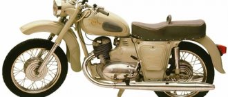
Models of IZH motorcycles are as unified as possible. The wiring diagram for IZ Jupiter 2 is not much different from later versions of the IZ motorcycle. There are external differences. For example, the Planet 5 bike has one cylinder, and the Jupiter 5 has two.
The first 12-volt motorcycle was the IZH Jupiter 4. The wiring diagram for the IZH Jupiter 5 and the wiring diagram for the IZH Jupiter 3 differ in components.
The bike of the fifth Jupiter has a contact SZ, which is powered by a battery, so the operation of the vehicle is highly dependent on the state of charge of the battery.
If charging is insufficient, the following problems occur:
- the motor runs intermittently;
- the engine starts with difficulty;
- At low speed the battery is discharged.
These problems can be eliminated by switching to BSZ. Any electrician can handle this task (the author of the video is Viter Electronic).
How to make the transition to contactless SZ?
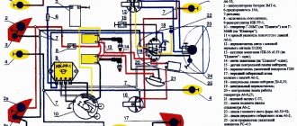
To switch to contactless SZ, motorcyclists use parts from other motorcycle models. When upgrading the generator set, the wiring of the IZH Jupiter 5 remains unchanged. Minor alterations concern the electrical circuit of the IZH. After changes, the battery is used to service auxiliary equipment. To switch to BSZ, parts are taken from Planet 5 and the VAZ 2108 car.
The following changes are being made to the electrical circuit of IZH:
- install 2 Hall sensors from the eighth VAZ model;
- 2 VAZ electronic switches must be connected to the sensors;
- each of the cylinders serves a commutator-sensor pair;
- You need to add two more ignition coils to the circuit.
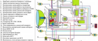
On the electrical circuit of the IZH motorcycle, the components are marked with numbers:
- Spark plug.
- Ignition coils from Planet 5.
- Switches.
- Hall sensors.
- Egnition lock.
- Battery.
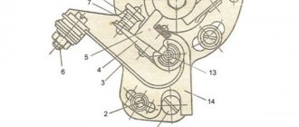
For the created ignition system, it is necessary to modify the IZ Jupiter 5 generator, the circuit of which will not require major changes.
How can I modify the generator?
The presented modernization option is advantageous in that it does not require the purchase of a new generator that will service the new ignition system.
Recycled generator design
All you need to do is follow these steps:
- make a modulator-breaker of an electrical circuit;
- install a breaker on the rotor shaft or generator.
You can create a modulator with your own hands. To do this, you need to take a metal plate and drill a hole in it for the fastening bolt. The manufactured part will serve as a modulator-chopper.
Homemade modulator for interruption
The modulator is connected as follows:
- install the modulator plate (2) and tighten it with the bolt (3), but not all the way;
- by rotating the crankshaft, you need to ensure that the piston is at top dead center;
- Next you need to set the ignition timing;
- Now you can tighten the mounting bolt on the plate.
Hall sensors (1) are installed together with the modulator.
Diode bridge for Izh Jupiter 5 installation
Motorcycle IZH - Jupiter 5 One of the diseases of IZH is charging the battery.
It is treated quite easily and simply. To do this you will need:
— relay-regulator from VAZ 2106
— 6 connecting chips (female)
- basic knowledge of electrical engineering
And so let's start the installation.
We disconnect wire “X1” from the BVP and screw it to ground. We disconnect the positive wire from the generator brush and connect it to terminal “67” on the RR. We also connect the positive wire from the ignition switch or from terminal “X8” of the BVP to terminal “15” on the RR.
Next, we connect a 5-pin relay, it is needed so that the charging indicator lamp goes out. We connect the positive wire from “X8” to terminal “30”. Connect terminal “85” to ground. We disconnect terminal “X3” from the BVP and connect it to relay “88”. We run a wire from terminal “86” and connect it to terminal “X7”.
Major problem with motorcycle wiring
On IZ Jupiter 5, the wiring had a large number of contact terminals. Therefore, the main cause of malfunctions in the electrical circuit was a violation of the integrity of the connections. This led to such moments as: there is no charging for the battery, the generator does not provide the necessary 12-volt voltage to the system, the switch is not able to generate the necessary charge for the ignition coil, loss of functionality of all lighting devices, and a number of others.
The cause of loss of connection in the terminals was contamination and oxidation of the contacts. This was especially true for motorcycles produced at the beginning of mass production. The main way to solve this problem was to exclude these terminals from the IZ Jupiter 5 wiring.
To do this, we used soldering the wires directly to each other (by analogy with), as well as sealing the terminals on the supply wires to the following main elements:
- battery;
- generator;
- coil and spark plug;
- switch;
- lighting devices.
This increased the reliability of the connections and, as a result, ensured the operability of the specified parts, and also made it possible to turn on charging for the battery in order to subsequently confidently start the engine of the IZH Jupiter 5 motorcycle.
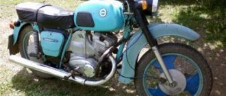
The history of motorcycles from the Izhmash plant begins in the 30s of the last century. During this time, many modifications of the IZH 1 - 6 bike were released. They are very popular. The article is devoted to the IZH Planet 5 bike, discusses its features, the IZH Planet 5 wiring diagram, and talks about maintenance.
[Hide]
Wiring diagram IZ Jupiter 5: alterations of the ignition system
Did you like the article? Follow our channel for new ideas of useful car tips. Subscribe to us in Yandex.Zen. Subscribe.
The main visual difference between the two motorcycles of the IZh family is the number of engine cylinders. The Jupiter 5 model has two of them, while the Planet 5 has only one.
In all other respects, the models are maximally unified with each other, with the exception of electrical components.
For reference: another design feature of the IZ Jupiter of the last 5 years of production is the use of water cooling. And Planet 5 has all air-cooled engines.
Motorcycle Features
The IZH Plante 5 motorcycle has the original name IZH 7.107. Just like the IZH 6, it belongs to the middle class of motor vehicles, designed for movement on roads with any surface. The main feature is the use of an oil pump; when refueling there is no need to add oil to the tank, as well as a contactless ignition system that operates independently of the battery.
It became possible to start a motorcycle from a pusher. To do this, you need to turn on the ignition, second gear and, when pushing the bike forward, the engine starts. True, without a battery, operation is possible only during daylight hours.
The Fifth Planet can be equipped with a cargo trailer and a passenger stroller. To reduce the clutch release effort, the bike has a clutch consisting of 7 pairs of discs. Vibration dampers are installed on the cylinder ribs. An important feature of this series is the presence of hydropneumatic suspension with disc brakes, which contributed to a smooth ride. The power is 22 horsepower, the maximum possible speed is 120 km/h. The volume of the two-stroke single-cylinder engine is 346 cm3. The power unit has good traction at low speeds.
Wiring diagram Izh Planet 5
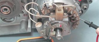
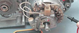
Unscrew the fastenings of the 5 upper wires.
Headlight of IZH 7 motorcycles. The main task of the new owners: Restore the electrical system - and there are no special problems with this, since the electrical wiring of IZH Jupiter 2 and Planet of the second and third generations is identical and interchangeable; Starting the engine is a more difficult task due to the need to overhaul the power unit and the availability of spare parts; Return the motorcycle to its original appearance. Guided by your knowledge of the electrical wiring of IZH Planet 5, you can easily restore the wiring on other motorcycles: the wiring diagram of IZH Jupiter 5 and its connections are similar. True, only in this state. Restoration process When the euphoria from the purchase wears off, a lot of questions arise regarding its repair and restoration with your own hands. True, without a battery, operation is possible only during daylight hours.
Rate this article. Motorcycle fuse IZH 7. To enlarge the diagram, click on it. The bike has the following control devices: a tachometer, on which there are indicator lights for the headlights and turns; speedometer showing total and daily mileage; power engine temperature indicator; Bike control devices Maintenance Anyone who loves their bike regularly monitors its technical condition.
Source
Maintenance
The owner can independently perform some maintenance procedures:
- check the motorcycle generator if the battery loses charge;
- set the gap between the breaker contacts;
- adjust the quality of the sound signal.
The need to inspect and adjust the wiring arises if:
- the motorcycle moves in the rain for a long time, as this causes oxidation of the contacts;
- a motorcyclist rides in an area with a lot of vegetation that damages wiring;
- The driver rides in snow in winter, which can stick to electrical wiring parts and damage them.
Self-check of the Planet 5 motorcycle generator in case of loss of charge
The cause of loss of charge in the IZH Planet 5 battery is most often a breakdown of the generator.
To check it yourself you need:
- multimeter device;
- straight screwdriver.
Step-by-step instruction
The following steps must be followed:
- Disconnect the wires from the battery and remove the generator cover.
- Disconnect the top 5 wires from the generator, first unscrewing their fastenings. In order not to mix up the wires during assembly, it is worth marking them.
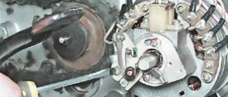
- Measure the winding resistance using a multimeter in ohmmeter mode. To do this, you need to touch the body with one probe, and the other should be connected in turn to the 3 wires of the winding. There should be no short circuits, as indicated by the inscription on the multimeter screen.
- Test the resistance between the stator contacts: you need to touch them one by one with the multimeter probes. The value on the screen should be 8 ohms.
The presence of a short circuit in the 3rd stage or a discrepancy in the indicators in the 4th will indicate problems with the generator.
Photo gallery: stages of checking the IZH Planet 5 generator in case of loss of charge in pictures
How to correctly set the gap between the contacts of the breaker?
In order to set the gap between the breaker contacts, you will need:
- straight screwdriver;
- wrench 10;
- candle key;
- probe 0.4 mm thick (+/– 0.05 mm).
Next, you need to follow the steps sequentially:
- Place the motorcycle on a stand and place the gearbox in neutral.
- Remove the right crankcase cover and unscrew the spark plug.
- Using a 10mm wrench, grab the generator rotor mounting bolt and turn the crankshaft to a position where the contacts are as far apart as possible.
- Loosen the screw securing the contact.
- Place the probe between the contacts and adjust the tightening of the eccentric screw until the probe passes the contacts with little resistance.
- Tighten the contact fixing screw.
Photo gallery: adjusting the gap between the breaker contacts
Troubleshooting the audio signal and improving signal quality
Poor sound signal quality is mainly caused by improper adjustment.
The following tools will be needed for setup:
- wrench 7;
- a simple screwdriver.
Step-by-step instruction
To adjust, do the following:
- Loosen the locknut with a wrench.
- Turn on the ignition.
- Press the button to turn on the sound signal.
- Adjust the sound by rotating the adjusting screw.
- When the desired result is achieved, tighten the locknut.
Electrical circuits of domestic motorcycles IZH Jupiter-5, Planet, IZH Junker, IZH49. To enlarge the diagram, click on it. You can also download for free and via a direct link an archive with circuit diagrams.
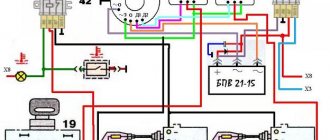
Electrical circuits of the ignition systems of the IZH Jupiter 5 motorcycle
1 - parking light lamp - A 12-4; 2 - high beam - low beam headlight - A 12-45:40; 3 - indicator lamp for generator operation - A 12-1; 4, 5 — speedometer scale illumination lamps — AMN 12-3; 6, 16, 17, 20, 23, 30 — lamps for the direction indicators of the motorcycle and side trailer; 7 - combination switch (right switch); 8 — brake light switch for the front wheel brake; 9 - breaker; 10 — spark plug; 11 — ignition coil; 12 - generator; 13 — rectifier-voltage regulator BPV14-10; 14 — brake light switch for the wheel brake; 15, 19 — side trailer clearance lamps — A 12-5; 18 — brake light lamp for side trailer — A 12-21-3; 21 — motorcycle brake light lamp — A 12-21-3; 22 — motorcycle rear marker lamp — A 12-5; 24 - battery; 25 - fuse; 26 — neutral lamp switch; 27 — ignition switch; 28 — sound signal; 29 — alarm switch (left switch); 31 — turn signal switch; 32 - high beam headlight control lamp - A 12-1; 32 — control lamp “neutral” — A 12-1; 33 - control lamp for direction indicator lights - AMN 12-3; Symbols on the BPV14-10 block (items 12,13): XI - “-” excitation windings; X2 - “-” battery (“ground”); ХЗ - “+” output to the control lamp; X4, X5, X7 - phases of the stator winding of the generator; X8 - “+” of the battery.