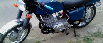
We would like to note right away that motorcycles of the IZH family were the most democratic and affordable form of transport in the 80s, which gave freedom of movement to many young men and adult men. In those years there was no Internet and cable TV, so wiping your pants on the couch was unfashionable. But the wiring diagram for the IZH Jupiter 3 was read to the gills by these same young men, which many adult aunts and uncles recall with nostalgia today.
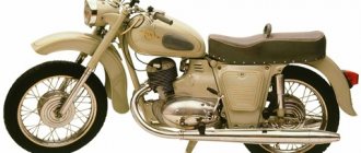
Legend in factory configuration
Model features
Therefore, even today, enthusiasts retrieve famous motorcycles from dusty sheds and garages, restore them to their original form and, as before, give the spirit of freedom to their owners.
Taking a motorcycle out of the woodshed, there is hope that it will return to service again
What is especially pleasing is the interest of modern youth in domestic technology. This article is intended for them and their parents who had the opportunity to ride Izhaks, Jupiters and Planets .
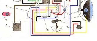
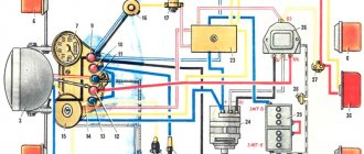
Electrical diagram
The IZH Jupiter 3 model appeared as an improved example of the previously produced IZH Jupiter 2. For the first time in domestic practice, a motorcycle received turn signals, and therefore the wiring diagram of the IZH Jupiter 3 has undergone changes.
In particular:
- There was a separate cable running under the gas tank and seat to the rear turn signals;
- For the model with a side trailer, a second cable was laid and attached to the stroller frame.
The new model is based on the proven electrical circuit of its predecessor.
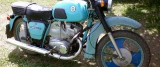
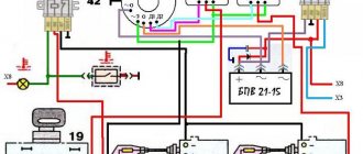
The photo above also shows the wiring on the IZ Jupiter 3 in the version with a sidecar.
They asked from her:
- Lamp (yellow) for trailer brake lights (indicated as 2a in the diagram);
- Lamp (red) for the rear marker light of a trailer (3a);
- Right direction indicator on the trailer fender (11);
- Trailer front marker light (white) (17).
One can argue for a long time about the quality of products of the domestic motorcycle industry, but a motorcycle in capable hands required only preventive maintenance and adjustment. And the era of shortages forced owners to show miracles of ingenuity, modifying unreliable components and assemblies of their two-wheeled horses.
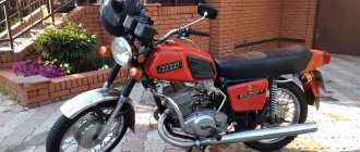
For reference: Izh Jupiter 3 deservedly received the Quality Mark. This was evidenced by a sign on the frame - in the photo below. Today, finding such a motorcycle without “crooked” improvements is a great success for collectors.
In comparison with imported “disposable motorcycle junk”, Planet 3 in capable hands served for decades
Self-improvement
Many were not satisfied with the capricious ignition of the motorcycle (see the article wiring diagram for IZH Planet 3), so the wiring diagram for IZH Jupiter 3 was often changed from 6 to 12 volt. This was facilitated by the appearance of the 281.3701 generator produced by the Izhevsk Motor Plant, which was much better and more reliable than the standard G36M7. Those owners who were not able to get it had to upgrade the existing one.
For this:
- A steel adapter plate was machined, allowing 12 internals to be installed in the generator;
- The right engine cover was purchased or exchanged from older models Jupiter 5 or Planet 5.
Exterior view of modified crankcase with steel plate
Technical specifications
- Overall length 2,115 mm
- Overall width 780 mm
- Overall height 1,025 mm
- Wheelbase 1,400 mm
- Ground clearance 135 mm
- Maximum speed 110 km/h
- Fuel tank capacity 18 l
- Highway range 360 km
- Fuel consumption on the highway is no more than 5 liters per 100 km
- Fuel: Gasoline with auto fuel in a ratio of 25: 1
- Fording capacity 300 mm
- Battery: 6V
- Engine Stroke 85 mm
- Cylinder diameter 72.0×85.0 mm
- Number of cylinders 1
- Cylinder displacement 346 cm3
- Compression ratio 7.51
- Maximum power 18 hp at 5,000-5,600 rpm.
- Air flow cooling
- Lubrication system combined with fuel
- Carburetor type K-36I, later K-62I
Izh Planeta-3K-01 in the countryside
Speedometer of the Izh Planeta-3 motorcycle
Motorcycle service
Unlike other models, both domestic and foreign (see the article for the wiring diagram of the Delta moped), the IZH Jupiter 3 is distinguished by its enviable survivability.
Here are a few instructions for resuscitating a motorcycle that has stood motionless:
- It is enough to replace or clean the candles yourself;
- Adjust the ignition;
- Replace high-voltage wires from the coils with spark plugs;
- Change the engine oil;
- Install a new battery or charge the existing one.
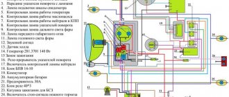
A modern scheme, more understandable to the younger generation.
And it will start and drive. And this is its distinctive feature, which is well known to the generation of the 80s. You can restore the old paintwork, reupholster the seat, or polish the chrome parts to a shine later, the main thing is its durability.
Advice: wiring IZ Jupiter 3 after long-term storage also requires close attention. Inspect it for abrasions and damage to the insulation. If any, replace the wires. Don't repair, just replace. How to do this - see the article Original Java 634 wiring.
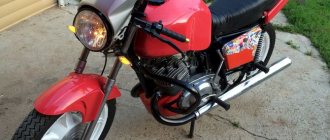
In the photo, the restored IZ Jupiter 3 (on the right) looks no worse than modern models.
In the video below you can get acquainted with the features of this model. It should be noted that the cost of restoration is quite affordable for most, and the difficulty lies only in the lack of spare parts and the need to modify those found from other models.
Setting up contact ignition on Izh Jupiter - 5
Let's take a step-by-step look at how to set up contact ignition on this device:
- Align the piston of the desired cylinder: - insert a screwdriver into the cylinder - rotate the crankshaft while holding the screwdriver
- Take a ruler and place it next to the screwdriver.
- Rotate the crankshaft, holding the screwdriver down with your finger so that it is level. We find a dead point.
- Turn the crankshaft in the opposite direction (1.5-2 mm).
- A spark is generated when the cam opens, locate the two adjusting bolts.
- Take a light bulb with two contacts, connect one to ground, the other to the contact.
- Turn on the ignition switch.
- You need to find the moment when the light comes on (the moment it lights up, the start occurs), and when it goes out, the contact closes on the contrary.
- Turn off the ignition, do and adjust the same with the second cylinder
conclusions
We hope that the electrical diagrams and video material presented in the article will help you in the maintenance and technical care of the IZH Jupiter 4 motorcycle. And thanks to your care, it will serve without fail for many more decades.
Constantly working to improve its models, in 1971 the Izhevsk Motorcycle Plant released a new motorcycle - IZH Jupiter 3, which had some differences from its predecessor.
In particular, the wiring diagram of IZ Jupiter 3 was modified, but the improvements turned out to be “capricious” and became the object of experimentation.
Installation process
It won’t take much time to replace the ignition, maybe a day. The necessary parts can be removed from the Oka vehicle. Electronic ignition is a set of wires, a generator, a two-terminal ignition coil, a Hall sensor and a switch.
There is no need to make any changes directly to the generator itself. You just need to remove the cams and, where there is space, attach a Hall sensor. It is very important that the modulator plate passes through the slots of the sensor itself. Thanks to the modulator plate, smooth ignition operation is ensured.
Unstable sparking is often caused by an incorrect design of the so-called magnetic flux contactor. In this case, you need to carefully study its placement in relation to the sensor. Overlapping of the magnetic circuit or magnet is unacceptable in the open state of the contactor, while the closed state of the contactor implies complete overlap of these two elements. If this is not the case, then most likely the sensor will emit weak signals to the switch. As a result, unstable engine operation will be observed.
To make a modulator you will need a steel disk with a cutout of 0.8-1 mm. It is important to maintain a ratio of closed to open periods of 2:1. The angle of the cutout in the modulator depends on the type of main power unit. If the main power unit is 1-cylinder, then the angle is 120 degrees. On 2-cylinder engines, an angle of 60 degrees is maintained. The width of the cutout starts from 11 mm and more, but not less. You should also know: a spark occurs when the modulator “opens” the sensor. This is very important when setting the ignition timing.
Before installing electronic ignition on the IZH Jupiter 5 motorcycle, check that there are no large plays on the generator shaft. If they are, you should replace the generator bearings in order to get rid of the “bumpiness”.
Changes made by owners
The unreliability of individual components and faulty wiring on IZ Jupiter 3 forced the owners to delve into all the intricacies of the modernized elements.
And the first to cause numerous complaints were changes in the primary circuit of power supplies:
- Battery;
- Generator.
As well as ignition systems and circuits for lighting devices of the trailer module - a cargo-passenger stroller. In most cases, the reason for the refusal was a banal manufacturing defect.
Battery charging system
Given the total shortage of spare parts for motorcycles that existed in those years, unplanned failure:
- battery;
- voltage regulator relay;
- ignition coils;
Tip: the regulator circuit presented above has been tested on many motorcycles of the IZh family. Its peculiarity lies in the separate power supply - when turned on, the ignition circuit receives “+” from the battery. And the excitation windings are powered from the generator (terminal “I”) and do not discharge the battery when the engine is stopped.
Generator replacement
The operation of the standard G36M7 DC generator also caused a lot of comments. Frequent breakdowns and unstable operation forced the owners to look for a replacement.
And among those that were freely available was the generator 281.3701, suitable for all series of “Planets” and “Jupiters”.
To re-equip the work it was required:
- Working generator 12 V;
- Block BPV 14-10;
- New 12-volt battery 6MTS-9, or another battery ZMT-8 (standard);
- New 12-volt light bulbs (to replace standard ones with 6V ones);
- Steel adapter plate for mounting a new generator;
- Right engine cover from IZH Planet 5 or Jupiter 5 models.
Advice: DIY alteration of the cover for a new generator can result in damage. Therefore, experienced owners recommend purchasing an original cover from “older” models, which was originally designed for its mounting dimensions.
The instructions for installing a new generator are very simple:
- The adapter is installed in the right half of the crankcase;
- Fixed with short bolts with a diameter of 6 mm;
- The stator of the new generator is connected to the adapter through M5 threaded holes using three screws.
Switching elements.
These include switches (high-low, turns, engine stop, etc.) as well as brake and neutral sensors and the ignition switch. You can easily “ring” them with a tester, finding out which contact group is not working.
Switching also includes the Izh electronic turn signal relay. Its malfunction is visible by the absence of interruption or no voltage supply to the turn signals.
As can be seen from all of the above, the wiring on Izh Planet is without any special secrets or complex elements, all its parts are easily diagnosed and repairs should not cause difficulties.
Now we advise you to watch the video, which shows in detail and clearly the assembly of the Izh Planet 5 circuit.
The IZ Jupiter 4 wiring diagram has become a revolutionary solution for all domestic motorcycles. It was with this model that the Izhevsk Motor Plant began to equip motorcycles with 12-volt equipment, which significantly increased spark generation in the ignition system.
conclusions
We hope that the proposed algorithm for refining the standard electrical system of the IZH Jupiter 3 motorcycle with video and photo materials will help you (see also). And you will use this method to upgrade your own motorcycle.
The charger disappeared somewhere and suddenly reappeared, it suddenly stalled during the journey or some mode does not work and the tidy is acting up - a common problem that needs to be solved. After many years of use, when you start to figure out what goes where and where, the roof goes askew, there are some twists, kilometers of electrical tape, oh yeah, things won’t work that way! I’ll say right away that I work at a car disassembly shop, getting wires or spare parts is not a problem, so, it’s decided and done - the wiring is made of Japanese wires and Chinese heat shrink. I spent a day on this. I didn’t buy connectors, I just opened them, took the wire of the required length, inserted it, clamped it, sealed it, put on a heat-shrink tube - hair dryer and voila! the wiring is ready :) then the whole harness is braided, we look and rejoice.
I decided to put up a horseshoe because I wanted to and that’s it! Is there too much room under the saddle for me? For supertuning, we will need a horseshoe from a vase (about 270 rubles), a relay-regulator (about 150 rubles), it’s better to buy it in a good store, make two brackets ourselves [-shaped (not visible in the photo, the relay is attached to them), an angle grinder. We “finalize” the relay regulator - we cut off a little meat (in the picture on the top left where the output contact is), we bend the contact itself inward, we also make two mounting holes, you can dig it out by hand with a 3 mm drill Using a grinder, we cut off the excess on the generator so that the diode bridge is without problems got in there. Everything is done locally and to the best of your imagination (we file the diode bridge so that the clutch cover does not touch it!). We secure the horseshoe with bolts - so that the diodes do not touch the ground, I used textolite washers. Yes, it’s not very beautiful, but it’s compact and has been working for the second season! Don’t forget, aluminum doesn’t solder well, so it’s better to make a hole, screw on a small bolt and nut and solder the positive wire to it!
In this picture everything is chewed in detail
BSZ! every homeowner's dream! I won’t describe the entire process of purchasing and components; there is plenty of information on the Internet. Like everyone else, I first decided to install a hall sensor (HH), I drove it for a ride, it works, but progress does not stand still! I found a replacement - the BS5-2M optical sensor! It costs quite a lot - about 250 rubles. The VAZ switch receives its signal without any problems. beautiful, but expensive, and if an arctic fox fails somewhere, it’s better to carry a spare one with you (if you still install BS5, I advise you to solder the body and side of the contacts carefully with a soldering iron, otherwise it may die from vibration) And finally, a few photos
We would like to note right away that motorcycles of the IZH family were the most democratic and affordable form of transport in the 80s, which gave freedom of movement to many young men and adult men. In those years there was no Internet and cable TV, so wiping your pants on the couch was unfashionable
. But the wiring diagram for the IZH Jupiter 3 was read to the gills by these same young men, which many adult aunts and uncles recall with nostalgia today.
Battery
The battery in the motorcycle is low-power. The motorcycle does not have a starter, so its task is only to supply voltage to the ignition system and the generator excitation winding during starting. Thanks to the battery, designed for 12 volts, a stable start of the fifth Planet is ensured; up to the third model, the wiring was 6 volt, and the ignition was not always clear.
Possible battery malfunctions:
- - housings, plates, leakage of electrolyte.
- - determined by measurements using a hydrometer.
- - detected by measuring resistance.
- minus not on the body (frame) of the motorcycle - all the electronics will not work.
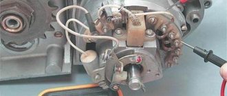
Generator
The heart is the generator (sometimes called a magneto, but they were never used on Izh Planet). Three windings produce alternating current. For excitation, an additional coil is used instead of a permanent magnet. Therefore, it is impossible to jump start a motorcycle with a completely dead or missing battery.
A diode bridge for current rectification and a voltage regulator assembled in one unit are mounted on the Izh Planet 5 generator (they are not even highlighted in the Izh Planet wiring diagram manuals).
Possible breakdowns in this unit:
- It is checked by measuring their resistance of current-carrying conductors and insulation. If the generator is damaged, it will become noticeably hot.
- — the output voltage will differ significantly from the nominal level or be absent.
- Although the electrical circuit includes short circuit protection, it happens that the automation does not work and most often the output transistor burns out.
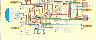
Dashboard
The new instrument panel fits well into the appearance of the new motorcycle model, combining:
- Speedometer;
- Automotive type ignition switch;
- Control and warning lamps.
The display of warning lamps separately from the instrument scales had a positive effect on the information content. Now the driver can easily see their readings, additionally provided with inscriptions.
It is also easy to replace burnt out lamps:
- Using a Phillips screwdriver;
- Remove 3 screws (in the diagram above under No. 3);
- Remove the cover;
- Remove the failed lamp;
- Install working;
- Reassemble the shield in reverse order.