Tuning Java 350, IZH, CZ, Ural, Dnieper
What is FUOZ and why is it needed?
FUOZ - ignition timing generator for any motorcycle with an electronic ignition system based on a Hall sensor or opto-sensor: Izh, Java, Dnepr, Ural, BMW, etc. It is also possible to manufacture it for carburetor cars with 4-cylinder engines.
Installed between the sensor and the switch on the signal wire.
For proper operation of the engine, it is necessary that the fuel-air mixture burns completely when the piston reaches TDC (top dead center). At this moment, the gas pressure is maximum and they push the piston down.
If you look at it, combustion of the working mixture does not occur instantly. From the moment a spark appears until the moment when the entire mixture ignites and the gas pressure reaches its maximum value, some time passes. This period of time is very short, but even during this time the piston manages to travel some distance from the position at which the mixture began to ignite.
Accordingly, the mixture must be ignited at some appropriate moment. Ignition timing is the angle of rotation of the engine crankshaft between the voltage supply to the spark plug and top dead center.
If the mixture is ignited later, for example, when the piston is already at TDC, then the maximum gas pressure will be reached later, when the piston has already traveled some distance down from TDC. The energy of the gases is lost and the power drops. If the mixture is ignited earlier than necessary, the piston has not yet reached TDC, but the fuel has already completely burned and the gas pressure reaches its maximum value even before TDC and prevents the piston from moving upward, the load on the engine increases, detonation occurs, power drops, the engine overheats and its service life decreases. .
The ignition timing is a very important parameter that greatly affects the correct operation of the engine. It primarily depends on engine speed: the higher the speed, the greater the ignition timing should be, because for maximum power the mixture must be ignited earlier.
In the standard ignition systems of Soviet-era motorcycles, the ignition was set to a certain specific advance before TDC (for example, 3.2mm for Java). In such situations, correct engine operation was achieved only at certain speeds: either at low, medium or high engine speeds.
The ignition timing generator (IAF) allows you to automatically change the ignition timing depending on engine speed. Thus, in any driving mode, maximum torque and maximum engine power are achieved, the mixture burns much better, the formation of carbon deposits on the piston and in the muffler is prevented, and the engine picks up speed faster. In a word - it comes to life.
In fact, automatic change in SOP is not a new thing today. Microprocessor FUOZ is already the fifth generation of automatic ignition timing regulators and is now even considered not a tuning, but a necessity. It is connected to the signal wire of the hall sensor or opto-sensor. In this case, the initial ignition timing angle for two-stroke engines should change and be 0.7-1.2 mm before TDC and
0mm if it is opposed (Ural, MT, K-750). We are talking about the well-known FUOZ of Saruman. It supports three different lead graphs and two additional functions to choose from:
— POWER WARMING — when the engine is turned off (there is no signal from the sensor) and this function is turned on, the controller continuously produces a spark with a frequency of approximately 1500 rpm; if the engine is running, this function does not work;
- PROTECTION 1500 or 2000 RPM - in this mode the engine can only operate at low speeds, when a certain number of crankshaft revolutions (1500 or 2000 rpm) is exceeded, the engine turns off, the indicator LED is constantly on, after the protection is activated, restart the engine can only be turned off and on;
— RPM LIMIT 3000 or 3500 or 4000 or 5000 or 6000 RPM — when this function is enabled, the controller limits the engine speed at the appropriate frequency, and the engine does not stall, but due to the passage of a spark, it stops gaining speed. This function can be used during break-in.
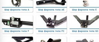
For a complete transition from a contact ignition system to a contactless system (BSZ), in addition to the FUOZ, you also need a hall sensor (or opto-sensor), a special curtain modulator that will pass through the sensor, a switch (it is best to take it from a VAZ car *.3734), wires which will connect it all, a platform for the generator and a sensor mount if an opto-sensor is used. The original coils for two-cylinder engines need to be replaced with one two-terminal one, for example from the Gazelle car 3012.3705, from the Oka car 4412.3705 and others.
Installation of FUOZ Saruman
I am very tired of adjusting the contact ignition in Java, I am very tired of the mood of the engine constantly living its own life. It trots, then sneezes, then it stupidly gains momentum. What’s most interesting is that at the age of 18 I didn’t care about it, the main thing was that it started, the rest were details, screwed the handle and flew. Now I drive more calmly and measuredly, plus the engine is running in, so much effort and money have been invested in repairing the engine, I want beautiful and clean work from it, but it doesn’t, I’ve already adjusted the ignition a dozen times with a micrometer, but it’s of little use. I decided to equip the motorcycle with a contactless ignition system with a hall sensor. Buy everything you need and install it on the motorcycle.
It starts, but does not reach more than 1000 rpm. I searched a lot on the Internet for the reasons for this behavior, thought a lot myself and tried different things.
In general, I moved away from this idea for some time, and drove on a regular cam ignition, quietly swearing to myself. As a result, after scouring the entire Internet, I found the possible causes of my malfunction. They could be:
- Using two 6 volt standard ignition coils connected in series. In general, you should install a two-spark coil from an Oka or Gazelle. (Although I read in one of the sources that standard coils can also be used.)
- Incorrect shape of homemade modulator. I made it in the form of a straight plate. (As it turned out, this was the main problem, since the plate was too narrow. In general, ideally, the modulator should be in the shape of a butterfly.)
- Using a hall sensor directly near the generator. In this regard, I can say that in principle it works, but there is still no buzz, since the hall sensor is a sensor that records changes in the magnetic field, and placing it near a permanent magnet is insanity. It's like measuring the air temperature in the open sun. Sooner or later, some problems will begin with the hall sensor.
In principle, I could eliminate all the shortcomings and use the usual VAZ BSZ (Contactless Ignition System). But in the process of searching for information on the topic on the Internet, I came across articles about FUOZ (Ignition Advance Angle Shaper), this is an electronic device that measures engine speed and, in accordance with their value, sets the most optimal spark delay. This approach allows for better combustion of fuel in the cylinders, and as a result, increased engine power, improved traction, fuel economy, and quicker revs. In general, a whole bunch of goodies compared to the ignition timing of a fixed value. What can I say, I was excited about this idea. On the Javaclub there is a huge amount of information on how to do it yourself, a complete manual and everything you need, although it will not be easy for a person ignorant of electronics to figure it out, but with a certain amount of effort, in principle it is possible, everything is very detailed there. And I probably could, but that’s the problem. All my attempts came up against the impossibility of finding suitable parts. But it doesn’t matter, it turns out there are people who make different versions of FUOZ to order and sell them online. Just off the top of my head, there are a couple of places where they sell FUOZ Saruman in different versions. As I understand it, FUOZ Saruman was designed by one person and others manufacture it and sell it. For example :
- https://vk.com/mega_bsz
- https://moto-navoroto.com/
- Personally, I took it here https://vk.com/fuoz_saruman
- There is also the BSZ Trabant. You can read about it here and order it only by contacting the author by E-mail [email protected]
In general, I decided that even if making it myself would cost less than buying a ready-made one, there would be disproportionately more fuss and work in this direction. My choice fell on https://vk.com/fuoz_saruman because everything is beautifully designed there, there are many photographs of products. there are a lot of customer reviews, it’s impossible to fake so much, there’s a lot of related information and the most important thing is that they sell a complete kit for installation with an optical sensor and not just a FUOZ. Placed an order and paid. Two weeks later, the seller sent the order by mail and received an international shipping code by which you can track its location on the Internet at https://gdeposylka.ru/ and https://moyaposylka.ru/. Which is what I did for 39 days. Yes, I didn’t expect that delivering a parcel from Ukraine to Belarus would be such a hassle.
And then she finally came, my joy knew no bounds. Not to mention the fact that in principle I love receiving all sorts of postal items, this parcel was the most long-awaited for me.
Inside was a complete set of ordered equipment, instructions and even a warranty card.
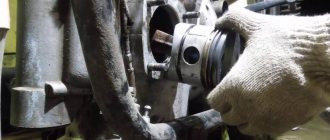
On the same day I started installing it on the motorcycle. I spent a couple of hours of time, but did everything carefully, ran all the wires through the main wires, all connections and connectors were soldered and insulated with heat-shrinkable cambric. I also bought an ignition coil from an Oka in the store.
I bought a four-position switch for the light in the car to switch the FUOZ modes. True, the insides of the switch had to be soldered to suit my needs. I actually attached it in a hurry; it was too interesting to test the device.
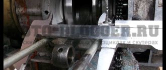
I installed a platform with an optical sensor and a modulator on the generator. I actually had to do a little work with a file because one slot on the platform slightly overlapped the hole of the mounting bolt on the generator, as a result of which it was impossible to secure the platform on the generator with a second bolt. Moreover, the error was not small; it was necessary to remove approximately the entire length of the semicircular cutout. 0.5mm. Well, these are minor things.
Since I have a 6-volt Java converted to 12, there is already not enough space under the crankcase cover for a generator; previously, its deficiency was made up for by a 5mm thick rubber gasket. This turned out to be not enough for an optical sensor and modulator. I had to expand the space. It’s good that I have a couple of engines for spare parts, I took the most damaged right crankcase cover from one of them and cut out half of the space I needed from it. Then, using a riveter and aluminum plates, I riveted it to my lid and gained the missing space. I actually had to replace the cover mounting bolts with longer ones. Having installed the cover in place, I realized that not everything is so simple. The brake foot no longer fits into place. It’s no problem either, I quickly drove it to work and, while heating it with an autogen, I bent the foot as needed so that it didn’t catch anything. The chrome was of course darkened and cracked. But sacrificing external shine for the sake of technical improvement of the device is quite acceptable.
Hurray, everything is ready, the motorcycle is completely assembled and ready for testing. I filled the carburetor with gasoline, inserted the key into the ignition, pressed the kickstarter, and the motorcycle started the first time. I am ecstatic, shocked to the core. I make a short shift and the engine stalls. Come on, I think, no matter what happens, the fuel probably doesn’t arrive. I pumped up the carburetor again and started it again with half a kick. Ahhh beauty has never turned on so well. And then she stalls again.
I removed the hose from the fuel tap, fuel flows in a cheerful stream, removed the carburetor, cleaned it and sorted it out. I must say that at the bottom of the sump there was some water with fine-grained dust, I thought that was the reason. I put everything together, I start the motorcycle, the picture is the same, it works for 10 - 15 seconds then stalls, at idle it works a little longer and stalls faster when the speed increases. I noticed that it is not necessary to pump up the fuel; to start the motorcycle again, you just need to turn off and turn on the ignition, and if you manage to do this before the engine stops spinning, then after turning the ignition off it continues to work. If it has already stalled, then pump it up, don’t pump it up, it won’t start until you turn off the ignition. Well, the point is clear, the electronics are to blame. I contacted the ignition supplier and explained the situation. He sent me to F.AQ
where is it written:
20. If the motorcycle starts and stalls after a while, but to start it, you need to turn off the ignition and turn it on again?
a) the switch freezes (the switch needs to be replaced. Some switches sometimes do not interface with the FUOZ and do not properly perceive its signal)
Recommended switches 96.3734, 961.3734, 133.3734, 0729.3734, 761.3734
b) Voltage surges in the on-board network (replacing the PSU with an electronic regulator)
This is checked by disconnecting one of the brushes on the generator so that the BSZ runs only on battery power. If, when the brush is disconnected, the motorcycle runs and does not stall, the BPV must be replaced with an electronic regulator and a diode bridge.
c) Insufficient power supply to the sensor (again due to the switch; can be treated by connecting the positive wire of the optosensor (NOT HALL SENSOR!) to the blue wire from the harness, that is, to +12V directly)
He said that I had case a) and advised me to buy another switch, option b) I checked as soon as I suspected problems with the electronics, c) that’s how it’s connected to me. The next day I went to the store and bought a switch from the recommended list, despite the fact that the one I received in the kit was already from this list. I installed it on the motorcycle and started it with zero effect. The problem remained the same.
To make sure that the problem is not in the switch, I made a BezFUOS plug. The FUOZ connector to the switch is a power connector from the computer power supply for older IDE devices and video cards. Since I am a former salesman and computer assembler, I have three bags in the attic, I took the “mother” from the video card power supply and shorted the wire that goes from the opto-sensor to the switch, the other two wires are +12 and there is no need to touch them. I turned off the FUOZ and all the problems disappeared. The motorcycle starts well and runs great. Well, I think I’m unlucky, the FUOZ is not working, the supplier says send it for diagnostics.
Yeah, send a month and a half there, no one knows how long it will be there, and a month and a half back, the prospect of receiving FUOZ for the new year was not at all encouraging. And then I remembered one incident.
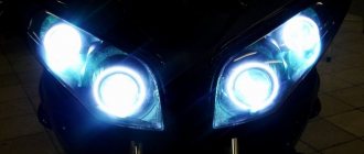
I remember about 5 years ago I wanted to install a bicycle speedometer on my moto, I bought this device at a nearby store and installed it on my moto. I spin the wheel, everything is ok. As soon as I start the engine, all the elements of the display light up on the screen and 8888, in general, the device is faulty. Then I went and bought silicone high-voltage plugs and new spark plug caps at the market. I installed it, no effect. I tried to shield the cable from the bicycle speedometer sensor itself, or rather I made it from a television cable, but it didn’t help.. In general, I installed that device on the bike and forgot about it, I decided that it was just Chinese crap in itself..
Now, with this FUOZ, I began to dig into the depths of the problem, since I felt with my fifth point that the problem was in the high-voltage electromagnetic field. I took a tester and measured the resistance in the caps, and it was 0.0.. The tuning silicone high-voltage cables also turned out to be crap, they are silicone blue and beautiful, but under the silicone there is another layer of plastic wrapping and inside there is a copper cable and that’s it. What kind of protection can we talk about? So, today I went to the store and bought VAZ high-voltage Tesla wires with distributed resistance. I installed it on the motor, and all the problems disappeared... FUOZ works..
The only negative in this whole matter is that I didn’t notice any difference between the FUOZ and the regular BSZ.. Well, maybe at idle the engine picks up better speed.. But while driving I didn’t notice any effect at all.. In general, don’t expect from Java that after installing the FUOZ it will become a sportbike.
In the end I actually got:
- Smooth operation of the engine, without farting or sneezing, the engine runs confidently in any of its feasible speed ranges, and does not falter.
- Easy engine start
- Setting up the ignition takes only 5 minutes and is not required in the future
- Very stable engine idling
- Vast experience in installation, troubleshooting BSZ + FUOZ
- Moral satisfaction from defeating the Contactless Drum
Special thanks to Nikola Tesla, What would we do without you.
Tags
- FUOZ
- Saruman
- BSZ to Java
- Optical ignition sensor
Saruman ignition to the Urals
One of the main pain points of heavy Ural motorcycles is the ignition system. Although currently motorcycles produced by IMZ are equipped with Italian-made Ducati Energia electronic ignition, only about three percent of the bikes produced today are sold in the Russian Federation. Most of the owners travel across the country using outdated mechanical ignition in the Ural. Electronic one has a number of advantages.
Modern replacement
This system has been considered outdated for almost half a century. Motorcycle owners often complain about oxidizing and burning contacts, the formation of an oil film, and the need to constantly clean and reconfigure the ignition system. Of course, inquisitive minds have already found a solution to this problem, so installing electronic ignition on the Ural is currently not something extraordinary.
Electronic ignition for the Ural motorcycle is now produced by several companies. The most common models are the SoveK microprocessor contactless ignition system, the Saruman ignition system, the Stary Oskol ignition system and the UKTUS-2 microprocessor ignition. Unfortunately, the last two systems are quite outdated, although they are still popular. In addition, there are a huge number of options for homemade systems. Many owners of motorcycles of this brand make their own ignition for the Ural. Electronic (or contactless) is superior in all respects to the old mechanical model, whose adherents remain only those who support the postulate “the older, the better.”
INSTALLING THE DEVICE ON A CAR
When installing the device on a car, the operation of the centrifugal and vacuum regulators is blocked: the weights of the centrifugal regulator must be secured using wire brackets instead of standard springs. The bearing race, on which the contact group of the breaker or the Hall sensor in the non-contact version is attached, is fixed with a metal plate connecting the race pin and the distributor body. The vacuum sampling hose for the OP angle regulator on the microcontroller is connected to the vacuum sampling pipe on the carburetor or intake manifold.
Any option can be used in a simplified form, i.e. without adjustment for vacuum. The standard vacuum regulator is not blocked in this case; input AN2 is connected to +5 V through a 10 kOhm resistor. The efficiency of the device in a simplified version will decrease. If input AN0 is not used, it must be supplied with a voltage equal to 1/2 of the microcontroller power supply (+2.3 V) from the divider through a 10 kOhm resistor.
The gap between the breaker contacts is set to the minimum possible (to reduce wear on the breaker cam), but ensures clear opening and closing of the contacts. After this, the initial angle of OZ is set: it must be equal to zero in relation to TDC and set according to the marks on the crankshaft pulley and the cylinder block when the engine is not running.
The transition to a microcontroller-based ignition system can be done in stages.
You first need to outline these stages for yourself, so that later there will be fewer alterations to the circuit.
· First, the block is assembled according to the diagram in Fig. 3 (for contact ignition system) or according to Fig. 4a/4b (for contactless ignition system). Unused ADC inputs are disabled (see above).
· Then the board is installed on the car, while the weights of the CR distributor are fixed. That's it, you can ride for your pleasure!
· If in the future you are going to connect a homemade vacuum sensor, use a slightly larger case in order to then place the sensor in it (if you plan to connect the DBP 45.3829, install a 5-volt stabilizer in the circuit to power the DBP, preferably on a zener diode and a resistor - like this more reliable).
The figure below shows an example of the design of an ignition unit with a homemade vacuum sensor
Of course, you shouldn't expect miracles from this device. “Zhiguli” will not turn into “Ferrari”, but they will drive very decently and at the same time consume noticeably less gasoline.
It is assumed that the engine is in good condition, the carburetor is adjusted in accordance with factory requirements.
If you fail to replicate the device, do not scold the author of the article and his program: read the text on the page carefully and you will find the reason for the failure.
The author does not recommend making changes to the circuits: apart from deteriorating performance and reliability (and sometimes complete inoperability), nothing will be achieved (this is especially true when replacing KS147 with 7805 or EH5). External devices (homemade tachometer) should be connected to the microcontroller ports via 3–10 kOhm resistors, and the resistors should be located on the board of the ignition unit - driver (the driver will work even if the tachometer connecting wires are shorted to the case). You cannot leave programmed but unused microcontroller inputs “in the air” (i.e., unconnected).
Optional.
It is possible to significantly reduce the error in the formation of the SPD at low speeds by installing a TDC sensor on the crankshaft pulley. Two options for implementing this option are discussed in the original author's article. Their implementation is quite labor-intensive and is not necessary when using a controller on a microcontroller, so they are not presented here. Those interested can familiarize themselves with them.
MBSZ "SoveK"
Sovek LLC has developed and successfully implements a microprocessor-based contactless ignition system for heavy Ural-type motorcycles. This option is suitable for those who do not want to bother with homemade units. The manufacturer promises improved starting in cold weather, increased engine stability by reducing spark asynchrony and optimizing the ignition timing, reducing exhaust toxicity, fuel consumption, stable starting even when the battery is discharged to a voltage of 6 volts, as well as preventing overheating of the ignition coil, which was one of the main problems of old systems. The main components are a modulator and a Hall sensor. Installing the SoveK ignition is quite simple, described in detail in the instructions and will take no more than half an hour.
Care must be taken to ensure that the modulator does not touch the Hall sensor. It is also recommended to replace old high-voltage wires with wires with distributed resistance. Reviews from motorcycle owners are rather positive, although some note a slight drop in power. Since the Soviet motorcycle, which needed to replace the contact ignition with an electronic one, has a rather worn-out engine, it is difficult to say how objective these assessments are. But many owners are very pleased that they installed this ignition on the Ural.
APPLICATION WITH CONTACTLESS IGNITION SYSTEM
This version of the program can be used to work with a contactless ignition system (instead of a breaker - a Hall sensor). The OZ angle former is assembled according to the diagram in Fig. 4a (for ignition coil 27.3705) or Fig. 4b (for coil B117A). If necessary, you can use a homemade inductive vacuum sensor (connected in the same way as in Fig. 3).
Rice. 4a. Device diagram for a contactless ignition system (coil 27.3705).
Rice. 4b. Device diagram for a contactless ignition system (coil B117A).
The operation of the driver was tested on VAZ 2109 and VAZ 21213 (Niva) cars.
Electronic ignition "Saruman"
The Saruman microprocessor ignition system is another way to quickly and without much hassle replace the outdated contact ignition of the Ural. Manufacturers promise the same set of advantages as the previous system. There are two configuration options: with a Hall sensor and with an optical sensor. The second option is somewhat more expensive, but it is usually recommended, since the optical sensor is more accurate and reliable. However, reviews from motorcycle owners are not as good as we would like, mostly complaints are made about the quality of assembly of parts. Another complaint is that the kit does not include an ignition coil.
MICROCONTROLLER FIRMWARE AND PRINTED BOARD
Printed circuit board
(pictures on the right) is universal and suitable for the manufacture of any version of the device. The elements are installed depending on the application. The board is designed to use SMD resistors, but if necessary, you can use MLT-0.125 resistors.
All parts are located on the conductor side; the foil on the opposite side of the board serves as a common wire and screen. Holes are drilled at the points where the leads of the parts connect to the common wire. The KT898A transistor is fixed to the radiator (metal casing) through a mica or fluoroplastic gasket.
Firmware check
in simulators it’s a waste of time, they (simulators) won’t tell you anything smart. If you want to make sure it works, check it on a breadboard using a two-channel oscilloscope and a PIC generator. Without instruments, the functionality of the microcontroller ignition system can be checked as follows: connect a spark plug to the high-voltage wire of the coil, open the breaker contacts (Fig. 3) and turn on the ignition. The program will operate in multi-spark start mode. For the circuit Fig. 4a, Fig. 4b, turn off the sensor and short-circuit the driver input to ground (the MK input cannot be connected directly to ground - it is possible that at this moment it is configured as an output, and this can damage the microcontroller). This mode can be used for burning carbon deposits and drying spark plugs, but, as a rule, with the multi-spark starting function there is no need for this - the engine starts reliably even with heavy carbon deposits on the spark plugs and with flooded spark plugs.
Download PCB drawing: F675OK.BAK
Download firmware for PIC12F675: F675OK.HEX
You can purchase a blank PIC12F675 controller at a retail outlet. You can flash a program into a microcontroller using an industrial or home-made programmer device, independently or to order.
ATTENTION! From us you can purchase a PIC12F675 microcontroller with the F675OK.HEX program already flashed at a fixed price of 250 rubles!
When ordering more than 5 pieces, the price is reduced.
Note. We do not sell this software. We provide services for firmware and supply of microcircuits. The program is distributed free of charge with the permission of the author.
Homemade electronic ignition system
The ignition for the Ural, electronic or contactless, can be assembled with your own hands. Such systems are assembled by craftsmen from improvised means. The main components necessary for operation are purchased at the nearest car market - a switch, for example, from a VAZ 2108, a Hall sensor and an ignition coil. The latter is often taken from Oka. Additionally, an interrupt modulator is assembled. The reliability of these systems leaves much to be desired, since the ignition timing is not always correctly adjusted in them.
The quality of the interrupt modulator is very important for such systems, but since high-precision tools are not available to many craftsmen, this negatively affects the result. Since for many Ural owners their motorcycle is not so much a vehicle as an object for technical experiments, sometimes very worthy examples appear.
IMPORTANT DIFFERENCE FROM PREVIOUS VERSIONS OF THE PROGRAM
Below is a table for generating the key closing time. The red color in the table indicates the accumulation time, which is insufficient for reliable ignition of the mixture. Under “MK is not normal.” implies the accumulation time generated by versions of programs from QRZ.RU (03.2008) and FTP of the Radio magazine (11.2008).
Effect of key closure time formation.
The table shows that older versions with a breaker as a TDC sensor and a B117A coil can form a spark with sufficient energy only at a Closed State Angle (USA) of the breaker contacts equal to 65 degrees.
Installation
It should be noted that there are quite a few ways to install electronic ignition on a Ural. It all depends on the model. You need to start by dismantling the old breaker and switch located under the saddle. Sometimes it is necessary to replace the ignition coil. Next, a modulator is mounted on the camshaft, a sensor is attached to the cover, and a new switch is installed. All that remains is to adjust the ignition timing.
Creating your own FUOZ, phase one. Data collection.
And then Ostap got carried away... I collected it on the planet for myself on Attyni2313, got the idea from the woofer, wrote it in ASMA, the usual redneck code. First I did it with a table, but with it the angle changes abruptly if you do it without interpolation. If you calculate the delay using a formula, and take points of, for example, 3-4 bends, then you will only need to tinker with selecting a formula for each section, since in ASMA I only know double division due to my denseness, i.e. For example, I had to multiply by 5 and then divide by 4; if it didn’t work out, I multiplied by 11 or 9 and divided by 8, that is, I played with the numerator (I selected it in regular Excel). The sensor was made from a mouse, due to the six-volt power of the Izha56, but it seems to me better to take an industrial one, or an inductive one, the optics are too exotic (if mass produced, then there is no market). It is better to calculate the speed immediately before the very early ignition moment, because The crankshaft rotates very unevenly (this is the case with a woofer). If you write in ASMA as I wrote above and without tables, even 13 tinks are enough. On the Atmega you can enter more parameters, for example put it under the accelerator pump, the air temperature, and just calculate the angle from the revolutions with the Atmega, it’s like hammering shoe nails with a pile machine IMHO.
For example, a program for the thirteenth tint with two angles up to 4000 thousand and after, high-impedance coil, Woofer principle: .include “tn13def.inc” .list
.def temp=r16
.cseg.org 0
rjmp reset reti reti reti reti reti reti reti reti reti
reset: in temp, mcusr andi temp, 247 out mcusr, temp ;clearing the wdrf bit of the mcusr register for the guard timer in temp, wdtcr ori temp, 24 out wdtcr, temp ;initializing the guard timer ldi temp, 11 out wdtcr, temp ;division factor guard timer ldi temp,low(RAMEND) ;select the top of the stack out spl,temp ldi temp,0x80 ;turn off the comparator out ACSR,temp ldi temp,47 out ddrb,temp ;port b to output ddrb4 to input
rjmp zdem1 ;go to curtain waiting check; zdem: wdr ;hereinafter, reset the watchdog timer sbic pinb,4 ;waiting for curtain rjmp zdem
rcall nul ;counter at 0 rcall zapusk ;start counter, division by clock cycles by 64 clr xh
provmax: cpi xh,20 brcs dalse ;to output if minimum speed, i.e. if sh>20 then go to zdem1
zdem1: wdr ;waiting procedure until the shutter comes out of the sensor at startup and at speeds less than the minimum sbis pinb,4 rjmp zdem1 rjmp zdem
dalse: wdr in temp,tifr0 sbrs temp,1 rjmp dalse1 rcall plus ;calling the SH increasing procedure when the counter timer overflows dalse1: sbis pinb,4 ;exit the cycle counting cycle rjmp provmax ;go to check the minimum speed clr temp out tccr0b, temp ;stop the counter in xl,tcnt0 cpi xl,30 cpc xh,temp brcs zdem ;set the output to maximum speed
ras4et: wdr mov yl,xl mov yh,xh mov zl,xl mov zh,xh cpi xl,$c9 cpc xh,temp brcs beta ;switch to beta angle if rpm is less than 4000
alfa: subi xl,80 sbci xh,0 rjmp iskra ;calculation of delay at rpm less than 4000
beta: add xl,yl ;calculation of delay at speeds greater than 4000 adc xh,yh add xl,yl adc xh,yh add xl,yl adc xh,yh add xl,yl adc xh,yh ldi temp,3
delenie: wdr lsr xl lsr xh brcc propusk ori xl,128 propusk: dec temp brne delenie
subi xl,10 sbci xh,0
mov yl,xl mov yh,xh
iskra: wdr rcall nul rcall zapusk rcall zaderzka sbi portb,3 mov yh,zh mov yl,zl rcall nul rcall zapusk rcall zaderzka cbi portb,3 rcall nul rjmp zdem
nul: clr temp out TCCR0B,temp out TCNT0,temp ldi temp,3 out tifr0,temp ret
zapusk: ldi temp,3 out tccr0b,temp ret
zaderzka: ldi xh,0 zaderzka1: wdr in temp,tifr0 sbrs temp,1 rjmp dalse2 rcall plus
dalse2: in temp,TCNT0 cp yl,temp cpc yh,xh brsh zaderzka1 ret
plus: inc xh ldi temp,3 out tifr0,temp ret
here is a link to the Excel file: https://exfile.ru/444237
By the way, when I tried to decompile the Woofer program, for some reason it turned out completely different from its source code, probably due to my crankiness. I won’t say anything about Saruman since I’ve never met him. Ps the power and control transistors must be used RF or microwave so that the spark front grows faster. Pps It’s better to switch to cdi because calculating the moment when a low-resistance coil starts charging to full current without switching it to resistor mode, at different speeds before it discharges into a spark, there is a great deal of confusion, and for me, for example, this is something in the realm of predicting the probabilities of the future. With CDI this problem does not exist at all.
FUOZ BSZ SARUMAN Factory production ORIGINAL
*** BUY Write to the group leader https://vk.com/id132344405 or click the buy button (above)
1. Last name, first name, patronymic 2. Your address 3. Postal code 4. Your motorcycle Sending by Russian Post (delivery time 5-9 days) or SDEK. The cost of delivery by mail within Russia is 250-350 rubles. Delivery to TC SDEK 100 rubles. Payment by Sberbank card. After sending, we write the tracking number of the shipment. Dispatch 1-2 days after payment. We temporarily do not ship cash on delivery. We ship to other countries. Belarus, Kazakhstan, Baltic states, etc.
Suitable for 12 and 6 volt power supply. Operating voltage range 5…16. B Operating temperature range: -40…+85 degrees C
The ignition unit (pictured) includes FUOZ+ switch functions. 3 UOZ graphics are recorded in the ignition at once
2 Functions to choose from ENGINE-STOP - when the function is enabled, the engine stalls, when the function is disabled, the engine runs; POWER WARMING - when the engine is turned off (there is no signal from the sensor) and this function is turned on, the controller continuously produces a spark with a frequency of approximately 1500 rpm; if the engine is running, this function does not work; PROTECTION 1500 or 2000 RPM - in this mode the engine can only operate at low speeds, when a certain number of crankshaft revolutions (1500 or 2000 rpm) is exceeded, the engine turns off, the indicator LED is constantly on, after the protection is triggered, start the engine again You can only turn the ignition off and on; RPM LIMIT 3000 or 3500 or 4000 or 5000 or 6000 RPM - when this function is enabled, the controller limits the engine speed at the appropriate frequency, and the engine does not stall, but due to the passage of a spark, it stops gaining speed. This function can be used during break-in.
ADDITIONAL PROGRAM FUNCTIONS
In addition to the above-described regulation of the ignition timing, the program has a number of additional functions that somehow improve engine performance.
Optimization of spark formation.
The program has a function to turn off the coil - if there is a constant low level at the input of the GP5 controller, after 2-3 seconds the output of GP1 is set to a high level. If GP5 is constantly high, the program generates multi-spark trigger pulses (see below).
In the range from 370 to 2000 rpm. the program generates an accumulation time of 12 ms; in the range above 2000 rpm. – maximum possible accumulation time. This allows you to obtain spark energy sufficient to reliably ignite the mixture in all engine operating modes and use the B117A ignition coil more efficiently. The heating of the coil at low speeds is reduced, and maximum speeds are easily achieved regardless of the gap in the breaker contacts.
Multi-spark start.
In the range from 0 to 370 rpm. Instead of one ignition pulse, the program generates a series of pulses with the following parameters: 2.3 ms is allocated for the spark, 12 ms for energy accumulation in the coil. The slower the starter rotates the crankshaft flywheel (CF), the more sparks occur each time the breaker contacts open (high level at the GP5 input). Multi-spark starting guarantees engine starting in severe frost, carbon deposits on spark plugs and flooded spark plugs.
Adjustment of OZ.
This version uses an additional ADC channel AN0, which can be used to shift the SCR by ±10 degrees relative to the original characteristic (Fig. 1).
The correction value is set by potentiometer R4. Instead of R4, in practice it is more convenient to use a switchable voltage divider. When the voltage at input AN0 changes from 0 to +5 V, the graph in Fig. 1 is shifted from –10 to +10 degrees relative to the original. At a voltage equal to 1/2 the microcontroller supply voltage (+2.3 V), the graph corresponds to Fig. 1. This channel can be used to regulate the SOP on a cold and warm engine - control from the choke button. Potentiometer R1 shifts the OZ by +5 degrees when the “suction” is extended on a cold engine (after setting R1, it is better to replace it with two constant resistors). Potentiometer R2 allows you to adjust the SOP manually with the air damper fully open (on a warm engine). The dependence of the voltage on the potentiometer sliders on the angle of rotation is nonlinear. R2 is located inside the car, which allows you to adjust the OZ on the go.
Maintaining XX speed.
This version of the program has a function for maintaining idle speed (idle speed) 930 rpm. To do this, on a warm engine (the headlights must be on), use the carburetor adjustments to set the speed to XX 900–930 rpm. When the idle speed deviates from 930 rpm. the program changes the SOP in the range from 7 to 14 degrees, setting the KV speed to 930 rpm. (correction along the AN0 channel is also taken into account and added to the range of 7–14 degrees). In practice, after appropriate adjustment, the speed remains constant when turning on/off the high beam headlights, heated glass and other consumers combined. Previously, you can turn off the “choke” when the engine warms up. You can get stable idle speeds with a lean fuel mixture. On a flat road, the engine “pulls” without jerking or jerking when the gas pedal is released in 1st, 2nd, 3rd and for a short time in 4th gear (this makes it easier to drive in icy conditions, in traffic jams, when driving over bumps - “riding tight”).
Adjustment for vacuum sensor.
The program has a function for automatically adjusting to the range of vacuum changes in the engine intake manifold, which simplifies the setup of a homemade vacuum sensor, and also allows you to use an industrial absolute pressure sensor (DAP 45.3829). The program independently determines the type of discharge sensor (by the maximum voltage at input AN2), therefore, in order not to mislead the program, do not configure the homemade sensor for a voltage greater than 2.3 V.
When using a homemade inductive vacuum sensor, the setting is reduced to setting the maximum voltage at the ADC input in the absence of vacuum and the minimum voltage at maximum vacuum (Fig. 2). To ensure greater accuracy in the formation of the SPD (in accordance with Fig. 1), the inductive sensor should be configured so that the maximum voltage at the ADC input is from 1.5 to 2.3 V, and the minimum is equal to or less than 0.9 V.
Rice. 2. Setting up a homemade inductive vacuum sensor.
The sensor is configured by selecting C3 and R10 before installing the unit on the car. Vacuum is simulated by moving the rod of the vacuum chamber from one extreme position to another.
Saruman ignition to the Urals
Ignition is possible in several options:
Small set: - switch (VAZ-2108) - advance board - Instructions Cost: 1200 rub.
Average ignition kit: - switch (VAZ-2108) - advance board - Hall sensor - wires, with connectors - Instructions - Shutter (Ural, Dnepr) - Mounting plate for the Hall sensor Cost: 2500 rub.
Complete ignition system: - switch (VAZ-2108) - advance board - Hall sensor - ignition coil (low resistance) - wires with connectors - Instructions - Shutter (Ural, Dnepr) - Hall sensor mounting plate Cost: 3500 rub.
Also in each ignition there are 2 additional ones. functions to choose from the list:
— speed limiter 3000,3500,4000,5000,6000 rpm.
Messages [1 to 20 of 25]
1↑ Topic by RaaF37rus 09-03-2014 16:36:24
- RaaF37rus
- Pro
- Inactive
- Name: Sergey
- From: Ivanovo region. Kamenka village
- Registered: 27-07-2013
- Messages: 568
- Reputation: 66
- Motorcycle: IMZ 8-103-10
Topic: Saruman Ignition
Guys, hello everyone! I ordered a lighter from Victor Pavlik - Saruman. In general, please share your experience, maybe someone has installed something like this, what is the best place to hang a fuoz, a switch, they recommend a coil from Oka with BSZ, and silicone wires, does the Oka coil fit into a standard place? There are a lot of videos about Saruman’s work itself, but what and who hung it where. I know that BOSS bought this, if you read it buddy, share what and how.