Electrical circuits of domestic motorcycles IZH Jupiter-5, Planet, IZH Junker, IZH49. To enlarge the diagram, click on it. You can also download for free and via a direct link an archive with circuit diagrams.
Electrical circuits of the ignition systems of the IZH Jupiter 5 motorcycle
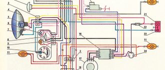
1 - parking light lamp - A 12-4; 2 - high beam - low beam headlight - A 12-45:40; 3 - indicator lamp for generator operation - A 12-1; 4, 5 — speedometer scale illumination lamps — AMN 12-3; 6, 16, 17, 20, 23, 30 — lamps for the direction indicators of the motorcycle and side trailer; 7 - combination switch (right switch); 8 — brake light switch for the front wheel brake; 9 - breaker; 10 — spark plug; 11 — ignition coil; 12 - generator; 13 — rectifier-voltage regulator BPV14-10; 14 — brake light switch for the wheel brake; 15, 19 — side trailer clearance lamps — A 12-5; 18 — brake light lamp for side trailer — A 12-21-3; 21 — motorcycle brake light lamp — A 12-21-3; 22 — motorcycle rear marker lamp — A 12-5; 24 - battery; 25 - fuse; 26 — neutral lamp switch; 27 — ignition switch; 28 — sound signal; 29 — alarm switch (left switch); 31 — turn signal switch; 32 - high beam headlight control lamp - A 12-1; 32 — control lamp “neutral” — A 12-1; 33 - control lamp for direction indicator lights - AMN 12-3; Symbols on the BPV14-10 block (items 12,13): XI - “-” excitation windings; X2 - “-” battery (“ground”); ХЗ - “+” output to the control lamp; X4, X5, X7 - phases of the stator winding of the generator; X8 - “+” of the battery.
IZh Planeta-5 (electronic ignition system) 1, 13, 28, 32 - lamps A 12-21-3 turn signal lamps; 2, 14, 27, 33 — direction indicator lights; 3 — control lamp A 12-1 “high beam”; 4 - lamp A 12-4 - parking light; 5 - headlight; 6 - lamp A 12-45-40 high beam - low beam headlights; 7 — indicator lamp AMN 12-3-1 direction indicator; 8 — control lamp A 12-1 “neutral”; 9 — control lamp A 12 “oil”; 10 — lamp AMN 12-3-1 speedometer lighting; 11 — speedometer; 12 — instrument panel; 15 - combination switch (right switch); 16 — brake light switch for the front wheel brake; 17 — ignition switch; 18 — sound signal; 19 — turn signal switch; 20 — spark plug; 21 — spark plug tip; 22 — ignition coil; 23 - switch; 24 - fuse; 25 - generator; 26 — sensor; 29 — lamp A 12-21-4 brake lights; 30 — rear light; 31 — lamp A 12-5 of the rear marker light of a motorcycle; 34 — brake light switch for the rear wheel brake; 35 — rectifier-voltage regulator; 36 - capacitor 2200 uF 63V; 37 — battery; 38 — oil supply valve-sensor; 39 — lamp switch “neutral”; 40 - alarm switch (left switch).
1 — headlight FG 137B2; 2 — lamp 12-45-40; 3, 4, 11, 12 — lamps A 12-1; 5 — sound signal S205B; 6 — thermal relay for turning on the electric fan 661.3710; 7 — electric fan; 8 — lamp switch “neutral”; 9 — lamp A 12-4; 10, 13 — lamp AMN 12-3-1; 14 - combination switch (right switch); 15 — switch IZHVK 103; 16, 28, 32, 35, 39 — lamps A 12-21-3; 17, 29, 34, 38 — direction indicator lights; 18 — overheat indicator sensor TM111; 19 — ignition switch; 20, 23 — spark plugs; 21, 24 — spark plug tips; 22, 25 — ignition coils; 26 — generator GP7; 27 — rectifier-voltage regulator BPV14-10; 33 — lamp A 12-5; 30 — switch IZHVK107; 31 — rear light 111.3716; 36 — battery; 37 - fuse; 40 — alarm switch (left switch); 41 - turn signal switch.
Leave it to mechanics or install electronics
Perhaps not all older motorcycle models are running. The Ural motorcycle sits and rusts in my grandfather’s barn because it won’t start.
The wheels are spinning, the engine is not jammed. Maybe the spark goes into the ground, as they say. In short, you need to look at the spark generation system. But even a working motorcycle, with a contact ignition system, causes unexpected and unpleasant problems for its owner:
- won't start when you really need it;
- with new oil rings in the engine, the spark plugs become covered with soot;
- there is no required engine power when driving with maximum load;
- the maximum speed is not reached;
- The battery is slightly discharged and the engine does not start.
Tuning a Ural motorcycle with your own hands - this article will help you decide in which direction to modernize your Ural.
The contact ignition system creates a lot of problems, especially when the moving parts in it have already worn out, backlash has appeared, and the geometry of the elements has changed.
The solution is simple - all cam ignition is thrown out, a modern electronic non-contact type spark generation system is installed. You will no longer have to deal with the thankless task of cleaning contacts and endlessly adjusting the gaps in the breaker. All this is possible thanks to the simple, but quite reliable design of the motorcycle. For example, it is quite easy to set the thermal gap and adjust the valves in the Urals with your own hands, using only your own tools from the garage. This way you will gain valuable experience and save money on visiting the workshop.
Maintenance
The owner can independently perform some maintenance procedures:
- check the motorcycle generator if the battery loses charge;
- set the gap between the breaker contacts;
- adjust the quality of the sound signal.
The need to inspect and adjust the wiring arises if:
- the motorcycle moves in the rain for a long time, as this causes oxidation of the contacts;
- a motorcyclist rides in an area with a lot of vegetation that damages wiring;
- The driver rides in snow in winter, which can stick to electrical wiring parts and damage them.
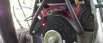
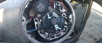
Self-check of the Planet 5 motorcycle generator in case of loss of charge
The cause of loss of charge in the IZH Planet 5 battery is most often a breakdown of the generator.
To check it yourself you need:
- multimeter device;
- straight screwdriver.
Step-by-step instruction
The following steps must be followed:
- Disconnect the wires from the battery and remove the generator cover.
- Disconnect the top 5 wires from the generator, first unscrewing their fastenings. In order not to mix up the wires during assembly, it is worth marking them.
- Measure the winding resistance using a multimeter in ohmmeter mode. To do this, you need to touch the body with one probe, and the other should be connected in turn to the 3 wires of the winding. There should be no short circuits, as indicated by the inscription on the multimeter screen.
- Test the resistance between the stator contacts: you need to touch them one by one with the multimeter probes. The value on the screen should be 8 ohms.
The presence of a short circuit in the 3rd stage or a discrepancy in the indicators in the 4th will indicate problems with the generator.
Photo gallery: stages of checking the IZH Planet 5 generator in case of loss of charge in pictures
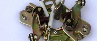
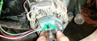
How to correctly set the gap between the contacts of the breaker?
In order to set the gap between the breaker contacts, you will need:
- straight screwdriver;
- wrench 10;
- candle key;
- probe 0.4 mm thick (+/– 0.05 mm).
Next, you need to follow the steps sequentially:
- Place the motorcycle on a stand and place the gearbox in neutral.
- Remove the right crankcase cover and unscrew the spark plug.
- Using a 10mm wrench, grab the generator rotor mounting bolt and turn the crankshaft to a position where the contacts are as far apart as possible.
- Loosen the screw securing the contact.
- Place the probe between the contacts and adjust the tightening of the eccentric screw until the probe passes the contacts with little resistance.
- Tighten the contact fixing screw.
Photo gallery: adjusting the gap between the breaker contacts
Troubleshooting the audio signal and improving signal quality
Poor sound signal quality is mainly caused by improper adjustment.
The following tools will be needed for setup:
- wrench 7;
- a simple screwdriver.
What does the contactless ignition system on the Ural and Dnepr motorcycle provide?
- No headaches for the motorcycle owner when operating it;
- Starting the engine in wet and cold weather;
- Failure-free operation of the ignition system;
- Increased driving characteristics of the motorcycle as a whole;
- Increased candle life;
- Starting the engine when the battery voltage drops to 6 volts;
- Constant, not changing over time, ignition timing;
- The ignition coil cannot overheat.
- Powerful, required color, sparking.
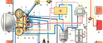
Wiring diagram IZH Planet 5
Detailed color wiring diagram for motorcycle IZH Planet 5
Explanations for the diagram
The numbers on the electrical diagram correspond to the following elements:
- Light switch, dimensions/low.
- Light switch, direction indicators and horn buttons.
- Front turn signals.
- Instrument panel lighting.
- Indicator lamp for generator operation.
- Oil pump operation indicator.
- A light indicating the operation of the neutral gear in the gearbox.
- Direction indicators.
- High beam headlight indicator.
- Front parking light bulb.
- Headlight lamp.
- Sound signal.
- Hall Sensor.
- Generator.
- Egnition lock.
- Turn signal interrupter relay.
- Neutral gear warning lamp sensor.
- Block BPV 14-10.
- Switch.
- Battery.
- Fuse.
- Relay block.
- Ignition coil.
- Foot brake light sensor.
- Rear direction indicators.
- Rear light with lamps.
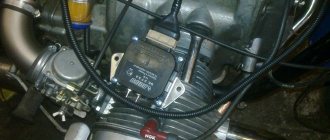
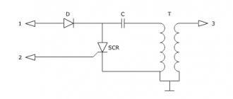
Briefly about the contactless ignition system
The contactless system, installed on all vehicles, includes:
- modulator i.e. Converter of magnetic flux into electrical impulses;
- magnetic flux sensors (for example, a Hall sensor);
- an ignition coil, slightly different in design from the traditional one;
- switch that distributes sparking;
- switching wires, terminals, fasteners.
The operating principle of a contactless ignition system is not complicated. A rotating plate mounted on the shaft, with its petals, opens and closes the path of magnetic flux (the magnetic field is formed by an installed magnet), which fixes the Hall sensor.
How to make an ATV from the Urals - this article will certainly be of interest to lovers of boxer engines and creators of real garage monsters.
These field breaks depend on the position of the distributor shaft. A pulse from a Hall sensor (or a similar one) occurs at a certain moment when the piston is at the required point for sparking. Next, instantly, the impulse is transmitted to the switch and to the ignition coil. The result is the formation of a spark in the spark plugs.
To mount the ignition system on a motorcycle, you need to either make its individual elements (modulator, plate) with your own hands, or purchase ready-made ESZ kits such as Saruman or Sovek.
Electronic ignition systems from Sovek and Saruman, equipment, features and differences.
If you don’t want to make electronic ignition elements for your Ural motorcycle yourself, you can purchase a kit ready for installation. Advantages of ready-made ignition systems:
- manufacturing takes place in a factory;
- the technical control procedure does not involve checking individual elements, but testing the performance of the entire system as a whole;
The most common and available for purchase are sez produced by SoveK and Saruman.
1. "Saruman". The package includes two options - with an optical sensor or with a Hall sensor. Any configuration includes an ignition unit, a platform for installing a sensor, a modulator with a flow interruption curtain, installation wires and installation instructions.
Features of the Saruman set:
- separate ignition timing generator (IAF);
- built-in system protection against generator overvoltage;
- LED indication to facilitate ignition setting
- microprocessor firmware is made for a specific motorcycle model;
- waterproof, locking connectors;
2. "SoveK". Several ignition system options are available. Microprocessor type and regular contactless.
The configuration can be with or without an ignition coil. Includes an ignition module, a modulator, and a switch with built-in FUOS.
Technical features of the Sovek kit:
- microprocessor module can work with various ignition coils;
- sparking is ensured both at low (6 volts) and at high voltage (16 volts) in the on-board network.
Electrical equipment IZH Planet 5
Wiring for IZH Planet 5 includes:
- generator;
- battery;
- ignition system;
- headlights;
- control devices;
- switching elements.
Video: review of IZH Planet 5 wiring
Taken by user Agronom.
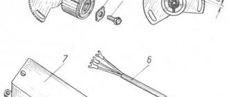
Generator
IZ Planet 5 generator design:
- voltage regulator with rectifier BPV-14-10 - 1;
- rotor - 2;
- stator with windings - 3;
- current collector brushes - 4;
- ignition system cam (battery) - 5;
- ignition system contact unit - 6.
The generator converts the mechanical energy of a gasoline engine into electrical energy, which charges the battery. Alternating current is generated by 3 windings and fed to a rectifier, which converts it into direct current. An additional coil is used as an exciter.
Photo gallery: IZH Planet 5 generator and its design
Battery
To supply all components, a low-power energy storage device of 12 volts is required, since IZH Planet 5 does not have a starter. The purpose of a lead-acid battery is only to supply voltage to the ignition system and the excitation winding of the generator during startup.
Ignition system
In IZH Planet 5, the ignition coil converts low-voltage voltage into high-voltage and transmits it to the spark plug. That, in turn, is responsible for the spark that detonates the fuel. To ensure that detonation occurs only in the desired piston position, there is an ignition chopper.
From the factory, this model is equipped with a classic ignition system, which requires periodic cleaning of the breaker contacts and adjusting the gap between them.
Installing a contactless SG on a motorcycle gives:
- timely powerful sparking;
- reduction of vibration levels;
- reduction in fuel consumption.
Control devices
The following control devices are installed on the motorcycle:
- tachometer, on which there are indicator lights for the headlights and turns;
- speedometer showing total and daily mileage;
- power engine temperature indicator;
- voltmeter.
Headlight and dashboard lamps
Conventional incandescent lamps are installed as lighting equipment and to illuminate the dashboard. Switching elements are responsible for supplying electricity from the battery to the lamps.
The headlight circuit includes lamps:
- headlight (35 watt);
- parking light headlights (4 W);
- control - blue light (2 watts);
- rear brake light (15 W).
Switching elements
Switching elements are various types of switches that close or open an electrical circuit. They can be activated using keys on the dashboard (for example, turn signals) or by sensors.
In IZH Planet 5, the switching elements include:
- turn switches;
- signal key;
- switches for low/high beam headlights;
- neutral sensor;
- egnition lock;
- foot and hand brake sensors.
Replacing spark plugs before installing electronic ignition systems
Spark plugs are the last element of the spark generation system in any engine. They work under conditions of high pressure and temperature.
Sparking occurs on them when a high voltage pulse is applied. Therefore, it is not possible to test them, without a test bench, in domestic conditions.
The serviceability of a working spark plug can only be judged visually - by carbon deposits on its tip or presence on the “skirt”. To ensure reliable engine operation, change spark plugs according to the motorcycle operating rules, without expecting them to work forever.
Choose the correct heat rating when purchasing spark plugs. Set the gap in the spark plug electrodes to 0.7-0.8 mm.
We hope that these problems with the spark plugs are not observed and, after purchasing (manufacturing) a non-contact type ignition system and replacing the spark plugs, we begin adjustment work.
Setting up and adjusting the ignition on Dnepr and Ural motorcycles.
The procedure for adjustment and tuning is the same for all motorcycle models. Features are associated only with the specifically installed electronic ignition system. General order:
- We install an electronic ignition system on a motorcycle;
- We set the ignition timing by turning the shaft and aligning the stamped arrow on the flywheel with the mark on the engine crankcase;
- We connect the wires according to the manufacturer’s diagram;
- Without turning the shaft, we adjust the position of: module, flow sensors (Hall, optical), modulator;
- We secure the elements of the ignition system.
- We rotate the shaft and control the formation of a spark;
- We adjust the optimal ignition timing after a test run.
When using 92 grade gasoline on motorcycles, we make adjustments from the standard ignition timing adjustment. We put it out a little earlier.
Installing an electronic ignition system will allow trouble-free operation of the motorcycle in any weather and climatic conditions.