Appearing in our country in the late 60s, the Czechoslovak motorcycle immediately became iconic. Its popularity was contributed not only by its speed, but also by the fact that the owner could easily provide it with technical care. The Java wiring was reliable, the components and assemblies were repairable, and maintenance was not burdensome.
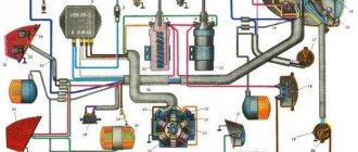
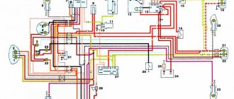
Original factory Java electrical circuit diagram for 6 volts
The colored wires indicated on the Java 634 wiring diagram have the following letter designations:
- red "A";
- blue "B";
- white "C";
- yellow "D";
- brown "E";
- green "F";
- black "G";
- gray "H".
Extreme.Newline.by
Motorcycle engines have either constant or variable ignition timing . With constant ignition timing , the beginning of the breaker break, and, consequently, the appearance of a spark, remains unchanged in all engine operating modes. With variable ignition timing, the moment of spark appearance is changed manually or automatically - with a centrifugal regulator, which, as the speed increases, increases the ignition timing from 10 to 30°. (see continuation)
In domestically produced motorcycles, the ignition timing according to factory data:
For two-cylinder engines M-61 and K-750, the breaker cam is a continuation of the camshaft, so the ignition timing is set at the factory. These machines have the same hammer break value for the right and left cylinders.
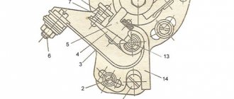
- - hole for decompressor;
- - rod for determining c. m.t.;
- — fixed contact of the breaker;
- — breaker lever;
- - fist.
The procedure for adjusting the ignition of a Java 350
Remove the right engine crankcase cover. Remove the spark plug and replace it with a device for determining the position of the piston. Turning the crankshaft with a wrench S=10 mm, placed on the head of the cam mounting bolt, place the piston in the idle position.
Set a gap between the contacts equal to 0.3 - 0.4 mm, to do this, loosen the screw securing the anvil and turn it around its axis in the desired direction. After tightening the screw, check the gap - a 0.3 mm thick feeler gauge should go through easily , but a 0.4 mm thick feeler gauge should not go through .
Connect the test lamp with one wire to the terminal clamp of the hammer, and the other to any ground point of the motorcycle. Turn on the ignition , and the lamp connected in parallel to the breaker contacts should light up.
Turning the crankshaft counterclockwise, lower the piston by the amount of ignition timing specified in the instructions. Count down according to the device. At the moment when the piston takes the desired position, the lamp should go out, signaling the closure of the contacts. If the contacts close earlier (the lamp goes out), it means the ignition is later , and later the ignition is early. In both cases, slightly loosen the screws securing the breaker disk and lightly hit the bent stop 12 (using a screwdriver) and turn it clockwise if the ignition is early, and counterclockwise if it is late. Tighten the base mounting screws and check the ignition installation. To do this, lower the piston 5 - 7 mm (the lamp does not light - the contacts are closed) and slowly raise it again. The lamp should light up (the contacts will open) at the moment when the piston does not reach TDC. by the amount of ignition timing (see TABLE ABOVE). Turn the crankshaft several times using the kick starter, and then check the ignition timing again when the piston moves to the top dead center. It should be remembered that when performing this work, you cannot keep the ignition on for a long time, so as not to damage the ignition coil.
On the Java-350 the ignition timing is adjusted in a similar way, first for the right cylinder - accordingly, the upper breaker, then for the left - the lower breaker. To do this, loosen the fastenings of the base (disk), and then for the left cylinder - the fastenings of the sector. To ensure synchronous engine operation, the ignition in both cylinders should be set to the same.
It sometimes happens that the required ignition timing of the JAVA 350 cannot be set due to the insufficient length of the groove limiting the rotation of the base. This indicates excessive wear on the breaker hammer stop or chipping. In this case, you need to replace the stop or install a new hammer.
During operation, the heel of the breaker hammer wears out and its height decreases. The anvil and hammer with contacts less than 0.5 mm thick are replaced with new ones. The wear occurs especially intensively after installing a new hammer. Changing the height of the heel of the hammer causes a change in the ignition timing.
Wear reduces the gap between the breaker contacts and the initial advance , and installing a new unused hammer to replace the failed one increases the gap between the breaker contacts and the ignition timing . Therefore, after replacing the breaker parts, it is necessary to adjust the ignition timing.
Ignition adjustment Java 638
The Czechoslovak motorcycle has a number of advantages compared to other Soviet units, but is almost the same in terms of electrical equipment. The JAVA 638 wiring diagram is quite simple. Even an inexperienced motorist can handle repairs and maintenance.
Adjusting the ignition of the JAVA 638 is very important for the correct operation of the engine. You can do it yourself at home. To do this you need:
- Remove the spark plugs from both cylinders and remove the sump cover.
- After removing the spark plugs, install the indicator in the hole of the right cylinder.
- Now you need to fix the piston at top dead center. To do this, turn the crankshaft using a key.
- Then the cylinder contact spacing is adjusted. They should only touch slightly (distance approximately 0.35 millimeters ).
- A light bulb is connected to the contact on which the advance is set. This is done before setting up the ignition on the JAVE 638, to accurately measure the distances between the contacts.
- Zero is measured on the indicator, after which the position is fixed.
- The advance is different for each gasoline. So, when using the 92nd and 95th, the adjustment is 2.7-3.1 millimeters, for the 80th – 2.9-3.3 millimeters.
- If the installation is correct, the light goes out. Otherwise, adjustment will be carried out by a movable disk.
- An identical procedure is carried out on the other cylinder.
- When the adjustment is completed, crank the crankshaft several times using the kickstarter. Then the control ignition advance is performed. This completes the YAVA 638 ignition installation.
It is important to understand that if the ignition is incorrectly measured, the engine's operating life will be reduced.
Ignition BSZ CDI, FUOZ, IZH, URAL, YAVA, TMZ
Sale of contactless ignition system (BSZ) for motorcycles IZH/URAL/DNEPR(K750,M61)/YAVA/TMZ/SNOWMOBILE BURAN/TAIGA 6-12 volts Show in full…
Any kit and parts (except cdi) can be purchased as a set or separately. Fuoz Saruman, optical sensors (slit and reflection), inductive sensors, pads, modulators-butterfly curtains, switches, adapter for Dnepr K 750, Saruman ignition unit (2in1 switch + fuoz), wiring with and without fuoz
You can ask questions in the comments of the photos and on the group wall. Sending by Russian Post with prepayment (cash on delivery is temporarily not available) and by transport company anywhere in Russia, Kazakhstan, Belarus, Moldova, etc., preferably “SDEK”, “ENERGY”.
In Ufa (Russia, Republic of Bashkortostan) you can pick it up. Before asking questions, please watch the video and discussions (->Prices)
Ignition BSZ with Fuoz Izh/Ural/Dnepr/Java/Buran/Opposit Buy ignition with Fuoz on an opto-sensor
Electrical diagram
The electrical circuit of the YAVA 638 has been modernized based on the wiring of the previous model. The experimental 12-volt equipment was completely replaced and required the installation of a larger battery. Features of this innovation:
- the appearance of a 210-watt generator;
- possibility of installing an additional fog lamp;
- The stroller consumers were provided with current from a standard generator.
Thanks to the new system, the level of luminous flux was increased, which ensured driving safety at night. Spark formation has also improved, which contributes to more uniform and dynamic engine operation.
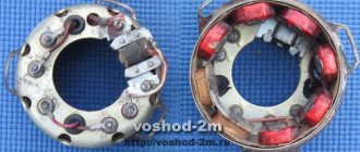
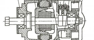
The new generator contains such basic elements as a rotor, stator and a metal casing. Its efficiency significantly exceeds the previously used 6-volt generator. This system allows charging even when the engine is running at low speeds.
However, the created system generated direct current, which needed to be converted into alternating current. For this purpose, a rectifier was built into the system. Its convenient location under the saddle makes it easy to carry out maintenance yourself.
However, when installing such equipment, the problem of overheating of the generator walls arose. It became impossible to use the rectifier inside a metal casing, so it was located under the driver's seat, providing air flow to cool the system.
The permissible power to a temperature of 150 degrees Celsius was 15 amperes. With the stroller and the use of all devices, it became possible to connect one additional consumer that does not require more than 40 watts of power.
Adjusting the gap between the contacts of the breaker and the ignition timing of the Java motorcycle
Setting the ignition timing is a very subtle and important adjustment.
The smooth and uninterrupted operation of the engine depends on the quality of this operation. Before you begin setting the ignition timing, it is advisable to make two devices that will greatly facilitate the upcoming work and increase its accuracy.
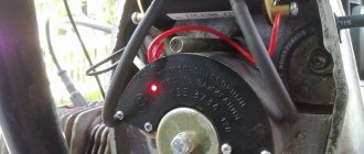
The first is a control light to determine when the breaker contacts begin to open. To do this, solder a crocodile-type contact and a connecting soft wire, also ending in a crocodile, to a regular 6 V, 1.5-5 W light bulb (see Fig. 35).
The second is an indicator for determining the ignition timing. A simple indicator can be made according to the drawing shown in Fig. 20; It is possible to make a more accurate device by adapting a dial indicator for this purpose.
Rice. 20. Indicator for setting ignition timing
Before starting the adjustment, it is necessary to inspect the breaker contacts, which must be in perfect condition and in full contact with each other. You cannot begin adjustment if the contacts are burnt or there are irregularities on their surfaces. Convexities on the contact planes must be eliminated. To do this, the breaker contacts must be removed and, carefully secured in a vice, the contact must be filed with a finely notched needle file in such a way as not to disturb the parallelism of the contact planes of the hammer and anvil contacts. Then it is recommended to polish the contact planes or at least sand them using fine-grained sandpaper. After finishing work, the breaker must be thoroughly cleaned of sawdust and washed in clean gasoline.
The plane of the newly filed contacts is checked by aligning them after installation in place. After making sure that the breaker contacts are in good condition and clean, you can proceed directly to setting the ignition timing itself.
The ignition timing of the Java-350 motorcycle must be adjusted in the following order.
1. Remove the spark plugs from both cylinders.
2. Remove the right crankcase cover.
3. Screw the indicator into the threaded hole of the spark plug in the right cylinder.
4. Set the piston of the right cylinder to top dead center (TDC) by turning the crankshaft with a wrench by the head of the bolt securing the generator rotor to the axle, or by rotating the rear wheel with direct transmission engaged.
5. In the position of the piston at i.d.t. set the gap between the contacts of the upper breaker (for the right cylinder) equal to 0.35-0.40 mm. To adjust the gap, it is necessary to loosen screw 8 (Fig. 27) securing the base of the anvil (fixed contact) and turn the base in the direction of increasing or decreasing the gap.
6. Having established the required gap between the contacts, turn the crank in the opposite direction and lower the piston 3.5-4.0 mm from the top. With this position of the piston and the ignition set correctly, the contacts of the breaker should begin to open and, accordingly, a spark should jump through the spark plug. It is most convenient to control the beginning of contact opening with a light bulb connected parallel to the breaker contact. When the ignition is turned on, at the moment the contacts begin to open, the light comes on, but when the contacts are closed, it does not light up.
To set the required contact opening moment, do the following:
a) loosen two screws 5 and 9 (Fig. 21) securing the main disk 7 to the body of the generator, and, turning clockwise or vice versa, install the disk so that the beginning of the opening of the breaker contacts coincides with the set position of the piston (3, 5-4.0 mm to b.m.t.); : the moment of the beginning of rupture is monitored by the flashing of the light bulb;
b) tighten screws 5 and 9 and again check the moment when the contacts begin to open; If necessary, if the adjustment is lost when tightening the screws, repeat the installation of the disk.
7. After setting the ignition timing for the right cylinder, set the ignition timing for the left cylinder. The sequence of operations and actions will be similar to those described above, but to adjust the moment when the contacts begin to open, you need to turn the base 2 of another breaker, attached to the main disk with two screws 1 and 4 (the main disk with the breaker for the right cylinder remains stationary). In no case is it permissible to adjust the gap between the contacts of the breaker after setting the ignition timing, since any change in the gap between the contacts significantly changes the amount of ignition timing.
Rice. 21. Motorcycle breaker "Java-350": 1 and 4 - screws securing the base of the left cylinder breaker; 2 – base of the left cylinder breaker; 3 — screw securing the base of the fixed contact of the left cylinder breaker; 5 and 9 - types of fastening of the main disk; 6 - protrusion; 7 - main disk; 8 — screw securing the base of the fixed contact of the right cylinder breaker.
Despite its apparent simplicity, ignition adjustment operations require certain skills. Complications may appear after final tightening of the screws securing the breakers to the base, especially if the screws were previously turned out significantly.
As the screws are tightened, the base of the breaker changes its position on the main disk (or the main disk changes position on the generator housing when adjusting the timing for the right cylinder). At the same time, the heel of the hammer changes its position in relation to the breaker cam; the gap between the contacts and the moment at which the contacts begin to ignite change accordingly. Therefore, when setting the ignition timing, it is necessary to take into account changes in the position of the chopper after tightening the screws and be able to make corrections to the measurements and to the position of the chopper before final tightening of the mounting screws.
Preventative maintenance of the ignition system. To ensure uninterrupted operation of the ignition system, the following rules should be followed.
1. Systematically clean the external ignition system devices from dust and dirt (ignition system devices must be spotlessly clean).
2. After 3000 km: a) lubricate with a drop of oil used for the gearbox, the fillets and the axles of the breaker hammers; b) check the condition and monitor the gaps between the contacts of the breaker and between the electrodes of the spark plugs; c) check the ignition installation and, if necessary, adjust it. To clean the breaker contacts during operation, use fine-grained sanding paper folded in half (Fig. 22).
Rice. 22. Cleaning the breaker contacts with sanding paper
This article is from the section - electrical equipment
, which is devoted to the topic of
adjusting the gap between the contacts of the breaker and the ignition timing of a Java motorcycle
. I hope you appreciate it!
What will you need?
To install the ignition from a scooter in Java, we will need a specific conversion kit. First of all, there is the generator itself; there are two models to choose from. The simpler QMB-139 will perform all the necessary functions, but problems may arise with the light at night, since the winding for the head light is rather weak and will greatly depend on the speed. If this parameter is important to you, then choose a stator from the QMI-157 or 152QMI model - they will be sufficient to achieve your goals.
You will also need an ignition coil with two terminals, here again there is plenty to choose from. For our purposes, motor coils ZMZ-406 or from Oka are suitable.
You will need a 12 volt battery. We don't need a new one; any used motorcycle or new Chinese battery will do. Its role is to smooth out voltage drops in the turn signal and stop signal circuits.
Also, do not forget about the set of wires/terminals. It is better to take the latter from Japanese scooters.
The last item is the adapter plate. Alas, it cannot be found on sale, but kind people have prepared the exact drawings presented below, according to which you can assemble your own adapter plate or order it. The thickness of the metal is 4 mm, this is an important parameter, because if you make the plate larger or smaller, some elements of the system may not fit or work incorrectly.
Top ads View all
Contactless ignition JAWA/JAWA 634-360-CHESET/CZ 472/3
Motorcycle parts and accessories » Motorcycle parts
1,000 UAH
Java Panonia Voskhod IZH BSZ generator 12v without battery cdi vape ignition
Motorcycle parts and accessories » Motorcycle parts
1,200 UAH.
BSZ Java IZH MT electronic ignition contactless system. Set.
Motorcycle parts and accessories » Motorcycle parts
440 UAH
CDI electronic ignition with Generator New on IZh Java Dnepr
Motorcycle parts and accessories » Motorcycle parts
1,000 UAH
CDI BSZ Java Jawa IZh Electronic ignition
Motorcycle parts and accessories » Motorcycle parts
Guaranteed to receive the goods or money back to the card More details.
1 150 UAH.
We install the ignition from the scooter to Java
First of all, we check whether our adapter plate is suitable, if so, then we attach it, install the rotor and stator. The latter should fit completely into the rotor; for convenience, we adjust the distance with washers. We install the sensor and make sure that everything rotates with a reserve and does not touch anything.
Now we need to modify the rotor. From the existing mark on the rotor, after 180 degrees we install a new mark. To maintain the accuracy of the procedure, it is best to use special devices that measure the angle of rotation; you can also use a lathe for this. We solder or weld the mark, obtaining 100% reliability of the unit.
The next step is to set the ignition timing. From the TDC point, we move the mark out from under the sensor by 2.5 mm, while the core should be located on the edge of the mark. The process is complex, so you should ask someone for help. The main thing is to securely fix the mark, turn it a few times and make sure that the settings still match.
Next, we set the gap, the optimal distance, between the plane of the mark and the core - 0.5 - 0.7 mm. To adjust, take a suitable probe and insert it between the mark and the core. The latter, under the influence of magnetic forces, will become at the optimal clearance distance. Next we make sure that the second gap is within the tolerances. If you have deviations in the gaps between the marks, you should make sure that they are within the acceptable values, otherwise the mark will have to be redone.
The next step is to assemble the circuit (wires, coils, etc.). To make it easier, you can use the diagram below.
Now, if you did everything correctly, you should check the operation of the entire system. First, we crank the crankshaft using a kickstarter, having previously unscrewed the spark plugs and placed them on the cylinders. The presence of a spark indicates that the electrical circuit is assembled correctly, but the accuracy of its settings can only be determined after the engine has been started. Smooth engine operation and responsiveness to gas are the first sign of success.
Types of BSZ
There are two types of BSZ:
— Single-channel (one Hall sensor, two-lobe modulator, one switch, one two-terminal ignition coil operating on two cylinders at once)
— Two-channel (two Hall sensors, one, or better yet two, modulator lobe, two switches, two ignition coils, one for each cylinder)
It is preferable to install a single-channel system, since it will be more stable, because here you do not have to adjust each cylinder (which you have to do at KSZ); here, if the modulator is properly made, then only one cylinder is adjusted. Also, in a single-channel one, fewer wires are used, its parts take up less space, and energy consumption is lower (which is very important for 6-volt generators)
There are many people who like to “get confused” who install a two-channel one, shouting at the same time that this way they can configure it more accurately, etc. I assure you that these are unnecessary hassles, and there will be no accuracy here (why is indicated above)
Spark plug. I said above that spark plugs “live” longer, which begs the question “Why?”
Actually the answer is simple. If you decide to install a single-channel BSZ (or a two-channel one with a two-lobe modulator), then this is what will happen:
When igniting in one cylinder, in the other, a spark will also strike at BDC, since it strikes simultaneously on both spark plugs, that is, spark twice per revolution on each spark plug.
What does this give? This allows for warming up and cleaning of the spark plugs at that moment the pistons are at bottom dead center, we get a smaller temperature difference between the spark plug electrodes (not allowing it to cool) and clean electrodes, ready for the new ignition of the fuel mixture. These factors, as practice has shown, increase the service life of candles.
PS Please note that spark plugs must be used exactly those that are designed for BSZ (when purchasing at a car store, you must indicate this to the seller)
What to do next?
Most likely, the ignition you assembled from a Java 634 scooter is rough and consists of twists, which is why you should replace them with normal terminals and twist the wires into braids. There is only a small matter left to do - completely replace all the remaining electrical elements, starting from the dashboard and ending with the head lighting and turn signals. Fortunately, now you have full 12 volts, so you can replace everything with spare parts from older models. On the other hand, 12 volts open up the opportunity to install almost any modern turn signal, high-quality lighting and many other useful devices such as a charger for a smartphone or an on-board audio system.
Comments
Yuri Kolotov:
Hello, how did you achieve charging 634 at idle? I have at least 1500 rpm
dimasikz:
When the key is inserted, the dynamo light should light up? java634
Edik Pivovarov:
I installed BSZ on Java 634 6v and it worked like clockwork for a week and then the spark became weak, what should I do?
Nikas3715:
Today I installed the original generator on my 634, it works even when it doesn’t charge at idle. I can make a video. switch 0529.
Mikhail Suchkov:
on Jupiter 3 do the same thing
OGSStudio:
will be as long as the battery holds its charge, as soon as it gets low it will stop working, so it’s better to charge
Miroslav Pavlyuchik:
and if there is no idle, will the BSZ work?
Dima Koryagin:
Ivan, to make it work, buy a VTN switch
OGSStudio:
watch the second video on installing “BSZ 2” on our channel, everything is already chewed down to the smallest detail. or go to our website on the forum in the topic “BSZ for 634 6 volts”, re-read the entire topic from the very beginning and you will find the problem. I’ll say right away that the problem is in the switch and battery, you can find out more from the above
Ivan Shavanov:
Today I posted everything as shown in the video (Java 350 633 6v) nothing works, I connect 12 volts, there is a spark, but from 6 there is no spark! Is this all bullshit or can you tell me what the problem is?
OGSStudio:
all this is discussed on our MOTO MASTER website, the link is in the description, and in the video itself there is a sign “to find out how to install. " etc. Just click on that inscription and a video on how to install all this will open
Gleb Rudakov:
Can you describe in detail how you did it and what you hooked up where (wiring). What kind of generator is there, 35w or 45w?
OGSStudio:
the modulator must be made as shown by me in the video on installing the BSZ, that is, the butterfly must be made according to the drawing indicated in the video
visn. Alex:
is the modeler homemade??
OGSStudio:
yes it will work, the main thing is that the charging is constant at all speeds, 6 volts is enough for such an ignition
visn. Alex:
Will this ignition work on Jupiter 3??
OGSStudio:
heh, if you have it working like that (not on the battery but on the generator) then it will be