How to replace the turn signal relay on a scooter - Scooter-Expert - online magazine about scooters and technology
A turn signal relay on a scooter is a necessary attribute for the correct operation of the turn indicators. If the turn signals suddenly change their blinking frequency, do not blink at all, or freeze in the on position, even though the wiring, battery and bulbs are in good working order, it is obvious that the turn signal relay needs to be replaced. Depending on the scooter model, its location can vary from the space under the front plastic to the rear of the scooter.
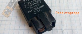
As a rule, the manufacturer tries to place the turn signal relay under the front plastic. In appearance, it is a small rectangular, cylindrical or square plastic object that resembles a starter relay in appearance. Let's take a step-by-step look at how to properly replace the turn signal relay on a scooter:
- We install the scooter on the central support.
- We determine the location of the turn relay specifically on your scooter; for this you can use the instruction manual for your model.
- The part is usually attached to the scooter frame with rubber clamps. We remove the relay.
- Carefully disconnect the plastic relay connector. Usually it is connected directly to the body of the part, without additional wiring, however, on some models you can find the example shown in the photo above.
- We connect a new turn relay to the on-board network and install it in place.
- All other plastic assembly operations are performed in the reverse order of disassembly.
As you can see, the procedure is very simple and even a novice scooter rider can handle it. If you still encounter difficulties during the process of repairing your scooter, you can use the comments field on our website, Scooter-Expert.com magazine will help you.
scooter-expert.com
Ignition circuit elements.
One of the most important electrical circuits in a scooter is the ignition circuit. It includes a CDI ignition module (1), an ignition coil (2), a spark plug (3).
CDI ignition module.
The CDI ignition module (1) is made in the form of a small box filled with compound. This makes it difficult to disassemble the CDI unit if it malfunctions. Although the modular design of this unit simplifies the process of replacing it.
There are 5 wires connected to the CDI module. The CDI module itself is located in the bottom of the scooter body near the battery compartment and is secured to the frame with a rubber clamp. Access to the CDI block is made difficult by the fact that it is located in the bottom part and is covered with decorative plastic, which has to be completely removed.
Ignition coil.
Ignition coil (2). The ignition coil itself is located on the right side of the scooter and is mounted on the frame. It is a kind of plastic barrel with two connectors for connection and a high-voltage wire output that goes to the spark plug.
Structurally, the ignition coil is located next to the start relay. To protect against dust, dirt and accidental short circuits, the coil is covered with a rubber cover.
Spark plug.
The ignition coil is connected to the A7TC spark plug (3) using a high-voltage wire.
The spark plug turned out to be cleverly hidden on the scooter, and it can take quite a long time to find it the first time. But if we “walk” along the high-voltage wire from the ignition coil, the wire will lead us straight to the spark plug cap.
The cap is removed from the candle with a little effort. It is fixed to the spark plug contact with an elastic metal latch.
It is worth noting that the high-voltage wire is connected to the cap without soldering. The insulated stranded wire is simply screwed onto the screw contact built into the cap. Therefore, you should not pull the wire too hard, otherwise you can pull the wire out of the cap. This can be easily fixed, but the wire will have to be shortened by 0.5 - 1 cm.
It's not so easy to get to the spark plug itself. To dismantle it, a socket wrench is required. With its help, the candle is simply unscrewed from its seat.
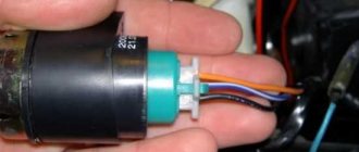
Starter.
Starter (8). The starter is used to start the engine. It is located in the middle part of the scooter next to the engine. It's not easy to get to.
The starting of the starter is controlled by the starting relay (10).
The start relay is located on the right side of the scooter frame. The starting relay receives a thick red wire from the positive terminal of the battery. This is how the start relay is energized.
Fuel gauge and indicator.
The fuel level sensor (14) is built into the fuel tank.
There are three wires coming from the sensor. Green is common (minus power), and the other two sensors are connected to the fuel level indicator (11), which is installed on the dashboard of the scooter.
The fuel sensor (14) and indicator (11) are one device and are powered by a constant stabilized voltage. Since these two devices are spaced apart, they are connected by a three-pin connector. The positive supply voltage is supplied to the fuel indicator and sensor via the black wire from the ignition switch.
If you open the three-pin connector coming from the fuel sensor, the fuel indicator will no longer show the fuel level in the tank. Therefore, if your fuel indicator does not work, then check the connecting connector between the sensor and the fuel indicator, and also make sure that they are receiving power.
It is also worth remembering that the supply voltage is supplied to the sensor and indicator when the ignition switch (12) is closed. According to the diagram, this is the right position.
Turns relay.
Turn relay or breaker relay (24). Serves to control the front and rear turn signal lamps.
As a rule, the turn relay is installed next to the instruments (speedometer, tachometer, fuel level indicator) on the dashboard. In order to see it you need to remove the decorative plastic. It looks like a small plastic barrel with three terminals. When the turn signals are on, it makes characteristic clicks with a frequency of about 1 Hz.
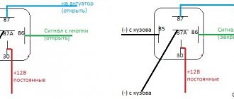
After the turn relay, a turn signal switch (23) is installed. This is an ordinary key switch that switches the positive voltage from the turn relays (gray wire) to the lamps. If you look at the diagram, when the switch (23) is in the right position, we supply voltage through the blue wire to the right front (21) and right rear (32) indicator lamp. If the switch is in the left position, then the gray wire is shorted to the orange one, and we supply power to the left front (19) and left rear (33) indicator lamp. In addition, in parallel with the corresponding indicator lamps (19, 20, 32, 33), signal lamps (20 and 22) are connected, which are located on the dashboard of the scooter and serve as a purely informational signal for the scooter driver.
Replacing the scooter turn relay
To move the scooter in the dark, the front headlight and rear brake signal are used. And to warn other road users about an overtaking or turning maneuver, turning lights are provided. However, in the dark, the continuous turn signal at the rear of the scooter will merge with the brake light and other drivers simply will not notice it. For this purpose, a flashing option for turns is provided on all vehicles. And to make this possible, a special relay is installed in the system for supplying electricity to the headlight bulbs. This means that the main purpose of the scooter turn relay is to provide an intermittent supply of electricity to the light bulb. It is because of this that it blinks at a certain interval.
The main indicators of partial or complete failure of the turn relay are:
- unstable or more frequent switching on (blinking) of turn signal lights;
- inability to turn on the turns (the light does not respond to the switch);
- The turn signal lights turn on, but do not blink (they just light up and go out only after they are turned off).
If such symptoms appear when the lamps and wiring are fully operational, then it’s time to replace the turn signal relay. And to do this, naturally, it is necessary to disassemble that part of the scooter that interferes with free access to this unit. In different scooter models, the location of the relay can vary from the area under the front plastic to the rear of the vehicle. Depending on this, the front or side parts of the scooter are disassembled.
When disassembling the scooter to replace the relay, you must:
- Place the scooter on a flat surface on the center stand;
- determine the location of the relay on this scooter, guided by the operating instructions;
- unscrew and remove the plastic at the location of the relay;
- release the part from the fastening clamps (in most cases they are rubber);
- remove the part;
- carefully disconnect the plastic connector of the relay (it can be either with or without additional wiring);
- connect the new relay to the on-board network;
- install the part in place and secure it with clamps;
- Reinstall the removed plastic and securely fasten it with the fixing bolts.
The procedure for replacing the turn relay is one of the simplest types of scooter repair, which even an inexperienced novice driver-owner can handle.
However, when replacing the turn relay, one should not neglect the general rules for all types of scooter repairs, namely:
- before starting disassembly, you need to thoroughly clean, wash and dry the scooter (especially hard-to-reach places and places most exposed to dirt);
- carry out repairs in a clean room and only using clean tools (keys, screwdrivers, containers);
- You should stock up on a container (or several) for storing small parts (bolts, nuts, O-rings).
After installing the new relay, you need to check its functionality by driving the scooter for some distance.
Source
Replacing the scooter turn relay updated: August 27, 2016 by: admin 2016-08-27
www.ezdaskut.ru
Do-it-yourself turn signal relay for a scooter - diagram
Very often, when replacing factory turn signals with LED ones, scooter owners have problems with the correct operation of the turn relay. This problem is common to all types of scooters - Chinese and Japanese, 2t and 4t, 50 cc and 150 cc mopeds.
Turn signal relay for scooter
To solve this problem when tuning a scooter, there are the following methods:
- buy an electronic relay for a scooter
- install additional resistance on the regulator
- make a turn signal relay for a scooter with your own hands
Setting the resistance is a bad option because when the turns are turned on, they consume electricity, causing the relay to “think” the turns have an incandescent bulb and not an LED.
Scooter turn relay diagram
So we will make an electronic turn signal relay for a scooter using a diagram (you can download it).
The circuit itself consists of three parts - a powerful field-effect transistor, a resistor and a flashing LED. All parts are not in short supply and inexpensive; they can be bought at any radio store or radio market.
Download the turn signal relay diagram
The best results are obtained with a flashing red LED. Everything is soldered directly using hinged mounting, output to output.
This is what the turn signal relay looks like on a scooter
The approximate cost of this scooter turn regulator is $2 with a time investment of 1 hour. Of course, if you don’t even know where the relay is on the scooter, then you don’t need to start soldering something right away - first read our articles on repairing and tuning scooters with your own hands. Happy DIY tuning!
skuterov.ru
Electrics and electrical equipment of a scooter
Dedicated to all owners of Chinese scooters...
To begin with, I would like to present a wiring diagram for a Chinese scooter.
Since all Chinese scooters are very similar, like Siamese twins, their electrical circuits are practically no different.
The diagram was found on the Internet and is, in my opinion, one of the most successful, since it shows the color of the connecting conductors. This greatly simplifies the diagram and makes it more comfortable to read.
It is worth noting that in the electrical circuit of a scooter, just like in any electronic circuit, there is a common wire. On a scooter, the common wire is the minus (-). In the diagram, the common wire is shown in green. If you look more closely, you will notice that it is connected to all the electrical equipment of the scooter: headlight (16), turn relay (24), instrument panel backlight lamp (15), indicator lamps (20, 36, 22, 17), tachometer (18 ), fuel level sensor (14), horn (31), tail light/brake light (13), start relay (10) and other devices.
First, let's go over the main elements of the Chinese scooter circuit.
Egnition lock.
Ignition switch (12) or “Main switch”. The ignition switch is nothing more than a regular multi-position switch. Even though the ignition switch has 3 positions, the electrical circuit uses only 2.
When the key is in the first position, the red and black wires are connected. In this case, the voltage from the battery enters the electric circuit of the scooter, the scooter is ready to start. The fuel level indicator, tachometer, sound signal, turn relay, and ignition circuit are also ready for operation. They are supplied with power from the battery.
If the ignition switch malfunctions, it can be safely replaced with some kind of switch like a toggle switch. The toggle switch must be powerful enough, because the entire electrical circuit of the scooter is, in fact, switched through the ignition switch. Of course, you can do without a toggle switch if you limit yourself to short-circuiting the red and black wires, as the heroes of Hollywood action films once did.
In the other two positions, the black and white wire from the CDI ignition module (1) is shorted to the housing (common wire). In this case, engine operation is blocked. In some scooter models, to block the engine, there is an engine stop button (27), which, like the ignition switch, connects the white-black and green (common, body) wire.
Generator.
The generator (4) produces alternating electric current to power all current consumers and charge the battery (6).
There are 5 wires coming from the generator. One of them is connected to a common wire (frame). The alternating voltage is removed from the white wire and supplied to the relay regulator for subsequent straightening and stabilization. The yellow wire removes voltage, which is used to power the low/high beam lamp, which is installed in the front fairing of the scooter.
Also in the design of the generator there is a so-called hall sensor. It is not electrically connected to the generator and there are 2 wires coming from it: white-green and red-black. The hall sensor is connected to the CDI ignition module (1).
Relay regulator.
Regulator relay (5). People may call it a “stabilizer”, “transistor”, “regulator”, “voltage regulator” or simply “relay”. All these definitions refer to one piece of hardware. This is what the relay regulator looks like.
The relay regulator on Chinese scooters is installed in the front part under a plastic fairing. The relay-regulator itself is attached to the metal base of the scooter in order to reduce the heating of the relay radiator during operation. This is what the relay regulator looks like on a scooter.
In the operation of a scooter, the relay regulator plays a very important role. The task of the relay regulator is to convert the alternating voltage from the generator into direct voltage and limit it to 13.5 - 14.8 volts. This is the voltage required to charge the battery.
The diagram and photo show that there are 4 wires coming from the relay-regulator. Green is the common wire. We have already talked about it. Red is the output of positive DC voltage 13.5 -14.8 volts.
The regulator receives alternating voltage from the generator through the white wire to the relay. Also connected to the regulator is a yellow wire coming from the generator. It supplies the regulator with alternating voltage from the generator. Due to the electronic circuit of the regulator, the voltage on this wire is converted into a pulsating one, and is supplied to powerful current consumers - the low and high beam lamps, as well as the dashboard backlight lamps (there may be several of them).
Failure of turn signals (turn signals do not work) Alpha moped
The turn signals on the Alpha moped
• •
relay
on
Alpha moped
•
The supply voltage of the lamps is not stabilized, but is limited by the relay regulator at a certain level (about 12V), since at high speeds the alternating voltage supplied from the generator exceeds the permissible limit. I think those who have had their dimensions burned out due to malfunctions of the relay-regulator know this.
Despite all its importance, the device of the relay regulator is quite primitive. If you pick apart the compound with which the printed circuit board is filled, you will find that the main relay is an electronic circuit consisting of a BT151-650R thyristor, a diode bridge on 1N4007 diodes, a powerful 1N5408 diode, as well as several wiring elements: electrolytic capacitors, low-power SMD transistors, resistors and a zener diode.
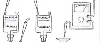
Due to its primitive circuitry, the relay-regulator often fails. Read about how to check the voltage regulator here.