From time to time, questions arise with turn signal relays when LED lamps are installed in the turn signals on a motorcycle, and not only on motorcycles, but also on cars, or when the turn signals themselves are replaced entirely with LED ones. Standard relays, as a rule, refuse to work with such light bulbs because the load is too small. It (the relay) perceives the LED lamp as a broken wire and begins to switch faster than usual. Under normal conditions, this is convenient: the relay began to “click” faster than usual, which means that some light bulb has burned out. But for someone who has consciously replaced incandescent bulbs with LEDs, this is the beginning of a headache. Just a few years ago, electronic turn signal relays for LEDs cost about 500 rubles, which is not at all humane. Then I just needed a relay for the LEDs. After scouring the Internet, I found an article about converting a conventional automotive three-pin electronic turn signal relay into a relay for LEDs. I did everything as described, everything worked, I forgot. But lately, apparently, spring is taking its toll, and the question of relays for LEDs has often come up. Anyone interested, please see cat. Compared to what it was a few years ago. the situation seems to have improved. So, literally today, while corresponding here with one of the forum members, who ordered himself a special turn signal relay for LEDs, I found out that the prices for these relays have dropped. According to this forum member, he ordered himself a relay for 170 rubles. Today, I bought a regular car relay at a car store for the same 170 rubles. I suppose that I could find it cheaper, because... this store is far from the cheapest, but I live in a small town, there are few stores, I stopped by another store, they ran out of relays. And I don’t see the point in going somewhere else because of winning 10-20 rubles. So, let's move on to the remake. To understand what exactly and how we will remake, here is a relay diagram: The basis of the relay is a specialized integrated (on a microcircuit) pulse generator that controls the closing and opening of a small-sized relay. The microcircuit has a special pin that monitors the voltage drop across the shunt. This drop depends on the total resistance of the lamps connected (in parallel). If a lamp burns out, the resistance increases, the voltage drop across the shunt decreases, and the microcircuit begins to switch faster. If this pin of the microcircuit is turned off, it will give pulses at a constant frequency, regardless of the number and power of connected lamps, which is exactly what we need.
In the diagram, the pin that needs to be disconnected is crossed out.
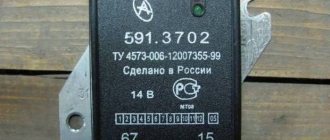
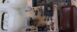
Now let's move on to practical implementation. I bought a relay like this: A wide strip of metal - it’s like the same shunt. View of the board with the microcircuit: We see the microcircuit. There is a dot on her body, it is always in the corner. This point calls the key. The key is always placed at the first pin of the microcircuit. The pins are numbered sequentially counterclockwise. If we return to the circuit, we need pin No. 7. I crossed out the conductor coming from him. This is the optimal place to cut the conductor. If someone buys another relay, more precisely, from a different manufacturer, the internals may differ in appearance. That's why I explain in such detail how to find the right conductor. I cut the track on the board with the tip of an ordinary knife, scratched it several times, saw that instead of the copper track the board was visible and that was enough. The current there is scanty, it won’t break through. The incision site is circled.
I would like to draw the attention of those who have a standard two-contact relay. This was exactly what happened on the old Yamaha R1-Z. Don't be scared! There is simply no mass wire there.
Relay connection. The relay has 3 outputs: 39 - ground, always connected. 49 - constant +, connects when the ignition is turned on 49a - signal, goes to the remote control, the turn switch and the emergency lights. To connect, you need to determine which wire is which in the standard wiring. If there is a diagram, good; if not, you need a test lamp. First, let's find the mass. One terminal of the test lamp is on the + battery, with the other we try the wires in the connector. The turn switch and hazard lights must be turned off. Where the lamp lights up, that is the mass output. We connect the wire of the probe lamp to any ground contact and try the wires in the connector, while not forgetting to turn on the ignition. But the lamp can light up in both wires (depending on the connection diagram of the control lamp in the device), so we turn on any turn signal or emergency lights. The wire where the probe lit up is the desired +. The remaining wire is the signal wire. You can check it by shorting the + and signal wires with the turn signals or emergency lights on. The turns should light up. If anyone is afraid, you can connect these 2 wires with a probe lamp, then the turn signals will light up, but dimly, and the probe is only slightly worse than when connected to the battery. And all because we turned on the turn signals in series with the probe.
Further, there are already possible options for who exactly will connect the relay to the standard connector. In such cases, I usually do not cut off the connector itself, but make an adapter from wires and terminals.
If anyone still doesn’t understand something, ask, I’ll try to answer. But I'll be away for the weekend, so there may be a delay in replies.
ps I made a video with the converted relay connected. If anyone is interested, please follow the link
How to replace the turn signal relay on a scooter - Scooter-Expert - online magazine about scooters and technology
A turn signal relay on a scooter is a necessary attribute for the correct operation of the turn indicators. If the turn signals suddenly change their blinking frequency, do not blink at all, or freeze in the on position, even though the wiring, battery and bulbs are in good working order, it is obvious that the turn signal relay needs to be replaced. Depending on the scooter model, its location can vary from the space under the front plastic to the rear of the scooter.
As a rule, the manufacturer tries to place the turn signal relay under the front plastic. In appearance, it is a small rectangular, cylindrical or square plastic object that resembles a starter relay in appearance. Let's take a step-by-step look at how to properly replace the turn signal relay on a scooter:
- We install the scooter on the central support.
- We determine the location of the turn relay specifically on your scooter; for this you can use the instruction manual for your model.
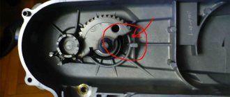
- The part is usually attached to the scooter frame with rubber clamps. We remove the relay.
- Carefully disconnect the plastic relay connector. Usually it is connected directly to the body of the part, without additional wiring, however, on some models you can find the example shown in the photo above.
- We connect a new turn relay to the on-board network and install it in place.
- All other plastic assembly operations are performed in the reverse order of disassembly.
As you can see, the procedure is very simple and even a novice scooter rider can handle it. If you still encounter difficulties during the process of repairing your scooter, you can use the comments field on our website, Scooter-Expert.com magazine will help you.
Replacing the scooter turn relay
To move the scooter in the dark, the front headlight and rear brake signal are used. And to warn other road users about an overtaking or turning maneuver, turning lights are provided. However, in the dark, the continuous turn signal at the rear of the scooter will merge with the brake light and other drivers simply will not notice it. For this purpose, a flashing option for turns is provided on all vehicles. And to make this possible, a special relay is installed in the system for supplying electricity to the headlight bulbs. This means that the main purpose of the scooter turn relay is to provide an intermittent supply of electricity to the light bulb. It is because of this that it blinks at a certain interval.
The main indicators of partial or complete failure of the turn relay are:
- unstable or more frequent switching on (blinking) of turn signal lights;
- inability to turn on the turns (the light does not respond to the switch);
- The turn signal lights turn on, but do not blink (they just light up and go out only after they are turned off).
If such symptoms appear when the lamps and wiring are fully operational, then it’s time to replace the turn signal relay. And to do this, naturally, it is necessary to disassemble that part of the scooter that interferes with free access to this unit. In different scooter models, the location of the relay can vary from the area under the front plastic to the rear of the vehicle. Depending on this, the front or side parts of the scooter are disassembled.
When disassembling the scooter to replace the relay, you must:
- Place the scooter on a flat surface on the center stand;
- determine the location of the relay on this scooter, guided by the operating instructions;
- unscrew and remove the plastic at the location of the relay;
- release the part from the fastening clamps (in most cases they are rubber);
- remove the part;
- carefully disconnect the plastic connector of the relay (it can be either with or without additional wiring);
- connect the new relay to the on-board network;
- install the part in place and secure it with clamps;
- Reinstall the removed plastic and securely fasten it with the fixing bolts.
The procedure for replacing the turn relay is one of the simplest types of scooter repair, which even an inexperienced novice driver-owner can handle.
However, when replacing the turn relay, one should not neglect the general rules for all types of scooter repairs, namely:
- before starting disassembly, you need to thoroughly clean, wash and dry the scooter (especially hard-to-reach places and places most exposed to dirt);
- carry out repairs in a clean room and only using clean tools (keys, screwdrivers, containers);
- You should stock up on a container (or several) for storing small parts (bolts, nuts, O-rings).
After installing the new relay, you need to check its functionality by driving the scooter for some distance.
Replacing the scooter turn relay updated: August 27, 2016 by: admin 2016-08-27
Signs that a check is needed
If the battery on your scooter often runs out, and it is still quite new, this means that there is a problem with the operation of the relay regulator. As practice shows, it burns out quite often. If the device is faulty, the battery stops charging completely and loses its capacity. This means you won’t be able to start the scooter with a button; you’ll have to start it with a kickstarter.
Another characteristic sign of incorrect operation of the device may be the frequent burnout of incandescent light bulbs. They themselves are durable and have a good durability, but are quite sensitive to voltage changes. This happens because the optimal voltage in the scooter network is considered to be 12-13 V. Increasing this value even by 2 V reduces the service life of electronics and components by 2 times.
The greater the deviation from the norm, the greater the likelihood that something will burn out in the scooter. Therefore, when starting the scooter from the starter due to a power surge and a faulty relay, the bulbs usually burn out.
Signs of a malfunctioning regulator are identical for all models of Chinese scooters. They are especially typical for charging relays for scooters of Chinese models with an engine capacity of 50 cc. Therefore, before making a decision to replace something in electronics, testing systems and devices should begin with the relay regulator.
Scheme and principle of operation
The operation of the stabilizer for all models is almost the same and consists in distributing the current supplied from the generator to stabilize it and further distribute it to consumers.
The operation of the stabilizer is almost the same for all models
The main peripheral consumers of the scooter include:
- battery;
- indicators;
- light bulbs;
- sensors;
- enrichment agent;
- other nodes;
- starting enrichment.
How does the stabilizer work? The main principle of its operation is to act as a transformer, which lowers the voltage to an optimal level acceptable for the operation of electrical appliances, and also stabilizes the network and prevents unexpected power surges.
If the relay malfunctions, the scooter’s devices fail, quickly wear out or burn out.
To avoid these problems and their undesirable consequences, you should know the basics of the correct operation of the electrical circuit and voltage components of the scooter (Figure 1).
Voltage relay pinout diagram and wiring for main scooter models
The pinout of the relay regulator is standard for all models of Chinese-made scooters.
Scooter relay-regulator pinout
The stabilizer has an aluminum body and plastic contacts, each of which has its own wire. Each contact has its own wire color. This makes it convenient to connect the device to the wires if the plastic connector is worn out. The wires must be connected to the contacts according to the electrical diagram (Figure 3).
Electrical diagram for connecting the relay regulator