The relay clicked, the tester beeped - everything is in order, the relay is working. After applying a control signal to the relay, the first output will become open and the second will become closed. We apply 12 volts to the winding from the power supply or battery - the relay should clearly click. Opening the trunk from the alarm key fob If your car has an electric trunk drive, you can connect to it with a car alarm to open it from the alarm key fob. It’s not bad when the power terminals are copper, and the winding terminals are nickel-plated steel. Examples of using relays for switching various devices are given at the end of the article. How to connect the relay
Examples of relay application: Engine blocking. Power contacts are always marked as 30, 87 and 87a. To do this, we need a power source with a voltage of 12 volts, a power supply or two wires from a battery and a tester turned on in resistance measurement mode. Poor contact generates heat. Connection diagram for central locking with an additionally installed activator and activators for alarms that do not have built-in central locking interface relays. Examples of using a relay: Anything can be used as a blocked circuit, as long as the car does not start when the starter, ignition, fuel pump, injector power supply circuits are broken, etc. Switching on through side lights or low beams The second option for the DRL connection diagram involves using the power circuit of the side light bulb. This scheme already has the right to life, since you can control the operation of the DRL depending on your driving conditions.
Let's cut this wire.
Connection diagram for an electric car radiator cooling fan
How to replace the turn signal relay on a scooter - Scooter-Expert - online magazine about scooters and technology
A turn signal relay on a scooter is a necessary attribute for the correct operation of the turn indicators. If the turn signals suddenly change their blinking frequency, do not blink at all, or freeze in the on position, even though the wiring, battery and bulbs are in good working order, it is obvious that the turn signal relay needs to be replaced. Depending on the scooter model, its location can vary from the space under the front plastic to the rear of the scooter.
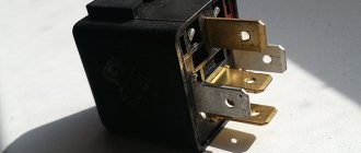
As a rule, the manufacturer tries to place the turn signal relay under the front plastic. In appearance, it is a small rectangular, cylindrical or square plastic object that resembles a starter relay in appearance. Let's take a step-by-step look at how to properly replace the turn signal relay on a scooter:
- We install the scooter on the central support.
- We determine the location of the turn relay specifically on your scooter; for this you can use the instruction manual for your model.
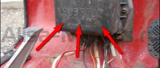
- The part is usually attached to the scooter frame with rubber clamps. We remove the relay.
- Carefully disconnect the plastic relay connector. Usually it is connected directly to the body of the part, without additional wiring, however, on some models you can find the example shown in the photo above.
- We connect a new turn relay to the on-board network and install it in place.
- All other plastic assembly operations are performed in the reverse order of disassembly.
How to replace the voltage regulator relay on a scooter
The voltage regulator on a scooter is an important element to ensure the normal operation of electrical equipment. It is he who is responsible for supplying a voltage of a certain nominal value to electricity consumers in the scooter’s on-board system.
Replacing the voltage regulator relay on a scooter may be necessary if the device fails.
One such example is stopping the supply of charging current to the battery contacts while the generator is working properly.
Let's take a step-by-step look at how to properly replace a scooter's voltage regulator on your own:
- We install the scooter on the central support.
- We determine the location of the voltage regulator relay in the device of your scooter model. If you do not have such information, use the manual for your device.
- Depending on the location of the part, the necessary elements of the scooter lining are dismantled. In some cases, you will need to remove the front plastic, sometimes the regulator is located in the back, and often its place is in the area under the “toilet”. For the latter case, it is enough to remove the seat area along with the seat to find the treasured regulator. Typically, this is a small aluminum device, slightly larger than a matchbox, with cooling fins to dissipate heat. The electrical connector goes to it.
- So, we have determined where the voltage regulator is located on the scooter; all that remains is to carefully replace it. Its body is usually attached to the frame or other components of the scooter using a bolt, rarely a self-tapping screw. The bolt can be an open-end wrench, often a hex wrench. We unscrew the relay from its seat, without losing the fasteners.
- Disconnect the connector chip.
- The new voltage regulator must fully correspond to the markings of the stock version, have a similar pinout and connector. When purchasing a part in a store, be sure to indicate the model of your scooter. If the seller has an idea about the product he is selling, choosing the necessary spare part will not be difficult for him. We connect the relay regulator to a standard connector.
- We install the part in its normal place, securing it with a fastener.
- We assemble the remaining parts of the scooter, for example, the plastic lining, in the reverse order of disassembly.
Electrics and electrical equipment of a scooter
Dedicated to all owners of Chinese scooters...
To begin with, I would like to present a wiring diagram for a Chinese scooter.
Since all Chinese scooters are very similar, like Siamese twins, their electrical circuits are practically no different.
The diagram was found on the Internet and is, in my opinion, one of the most successful, since it shows the color of the connecting conductors. This greatly simplifies the diagram and makes it more comfortable to read.
(Click on the image to enlarge. The image will open in a new window).
It is worth noting that in the electrical circuit of a scooter, just like in any electronic circuit, there is a common wire. On a scooter, the common wire is the minus (—). In the diagram, the common wire is shown in green. If you look more closely, you will notice that it is connected to all the electrical equipment of the scooter: headlight (16), turn relay (24), instrument panel backlight lamp (15), indicator lamps (20, 36, 22, 17), tachometer (18 ), fuel level sensor (14), horn (31), tail light/brake light (13), start relay (10) and other devices.
First, let's go over the main elements of the Chinese scooter circuit.
Egnition lock.
Ignition switch (12) or “Main switch”. The ignition switch is nothing more than a regular multi-position switch. Even though the ignition switch has 3 positions, the electrical circuit uses only 2.
When the key is in the first position, the red and black wires are connected. In this case, the voltage from the battery enters the electric circuit of the scooter, the scooter is ready to start. The fuel level indicator, tachometer, sound signal, turn relay, and ignition circuit are also ready for operation. They are supplied with power from the battery.
If the ignition switch malfunctions, it can be safely replaced with some kind of switch like a toggle switch. The toggle switch must be powerful enough, because the entire electrical circuit of the scooter is, in fact, switched through the ignition switch. Of course, you can do without a toggle switch if you limit yourself to short-circuiting the red and black wires, as the heroes of Hollywood action films once did
In the other two positions, the black and white wire from the CDI ignition module (1) is shorted to the housing (common wire). In this case, engine operation is blocked. In some scooter models, to block the engine, there is an engine stop button (27), which, like the ignition switch, connects the white-black and green (common, body) wire.
Generator.
The generator (4) produces alternating electric current to power all current consumers and charge the battery (6).
There are 5 wires coming from the generator. One of them is connected to a common wire (frame). The alternating voltage is removed from the white wire and supplied to the relay regulator for subsequent straightening and stabilization. The yellow wire removes voltage, which is used to power the low/high beam lamp, which is installed in the front fairing of the scooter.
Also in the design of the generator there is a so-called hall sensor. It is not electrically connected to the generator and there are 2 wires coming from it: white-green and red-black. The hall sensor is connected to the CDI ignition module (1).
Relay regulator.
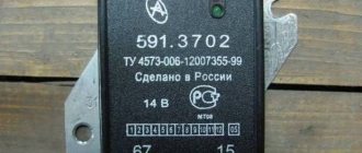
Regulator relay (5). People may call it a “stabilizer”, “transistor”, “regulator”, “voltage regulator” or simply “relay”. All these definitions refer to one piece of hardware. This is what the relay regulator looks like.
The relay regulator on Chinese scooters is installed in the front part under a plastic fairing. The relay-regulator itself is attached to the metal base of the scooter in order to reduce the heating of the relay radiator during operation. This is what the relay regulator looks like on a scooter.
In the operation of a scooter, the relay regulator plays a very important role. The task of the relay regulator is to convert the alternating voltage from the generator into direct voltage and limit it to 13.5 - 14.8 volts. This is the voltage required to charge the battery.
The diagram and photo show that there are 4 wires coming from the relay-regulator. Green is the common wire. We have already talked about it. Red is the output of positive DC voltage 13.5 -14.8 volts.
The regulator receives alternating voltage from the generator through the white wire to the relay. Also connected to the regulator is a yellow wire coming from the generator. It supplies the regulator with alternating voltage from the generator. Due to the electronic circuit of the regulator, the voltage on this wire is converted into a pulsating one, and is supplied to powerful current consumers - the low and high beam lamps, as well as the dashboard backlight lamps (there may be several of them).
Garage
I had a wonderful motorcycle Zizer 400 -98. And one day this happened: after riding, I drove to a gas station and filled the tank full. It’s already dark outside, I go to the motorcycle, look at it, my eyes are happy, my emotions are overwhelming. I sit down, press the starter and figs - there’s some kind of crackling noise, the starter doesn’t turn. I called my friend, explained the situation, he said he would come. I'm waiting, sir, I arrived in about 10 minutes. We didn’t think long about it, it was too late to get to the garage 1-2 km away, so we decided to try to start it with a pushrod. It started up with a bang from the pushrod, but the headlight does not light up. I drove without a headlight, fortunately my comrade was driving ahead and had his headlight on.
Video for those interested. (you don't have to watch it :))
It was night outside, I didn’t bother to rack my brains, I stomped home with heavy thoughts. The morning is wiser than the evening. The next day I went to the garage to solve the problem. I started dancing from something simple. We diagnose fuses. I checked. They turned out to be all intact.
I took a photo of the fuse box in the garage.
I decided to start the horse again, and oh mystic horror... the starter spun, then silence. Then a neighbor in the garage came, we don’t leave our own people in trouble. The neighbor came not empty-handed, but with a multimeter. I measured the voltage on the battery and it read 10V. Dead acc, such a bastard.
I took this parasite home and put it on charge. It took three hours to charge. brought it to the garage. I installed the acc, and yay - the engine started up BUT the headlight does not light up
Okay, I think I got burned. In general, the battery charge was enough for three engine starts. I put it in the garage to charge, the voltage is low, charging will take a long time. In order not to waste time, I went to inspect the connectors and terminals for melting/oxidation. Everything is clean everywhere - makes me happy!
I flew to the store, bought a new light bulb, inserted it into the socket without putting on the muzzle - it lights up, hurray, hurray, hurray. And then my natural curiosity takes over, let me think, I’ll put the old one on, check for lice, so to speak... /drumroll/, the same thing - it’s burning O_o Profuse sweating and mental circulation began. I asked my neighbor to measure the voltage with the engine running at 4000 rpm, it showed 14V, which means the generator is working and I’m happy. “Perhaps there is a short circuit, a short circuit somewhere? “, I say to my neighbor. He advises checking using the old-fashioned method - we remove one terminal from the aka. We put a light bulb between the terminal and the cable, turn the key to the ON position and the light comes on. “It’s not short,” says the neighbor.
I decided to buy a new battery since there was such a binge. As in the song: walk, walk. Bought. Now it starts normally and the horror of mysticism continues to repeat itself, now the headlight is on, now it is not. Started it - it lights up. Turned it off. Turned it on again and it no longer lights up. After several tests it stopped starting again, rattling noise, sweating, mental disturbances (I already have the last one).
Video to break up so much text:
Now it’s the turn of my dear relay regulator (RR)
The manual has several ways to check PP:
Method 1: The lamp should not light on more than one terminal. It lit up happily at terminal Y3. My sadness knew no bounds
Go ahead. Method 2:
Here, too, the lamp should not be lit. Again on Y3 it lit up for me. There is no point in continuing further. RR is dead. It is a thankless task to revive, because it is difficult to disassemble and after tearing apart this rubber casing, it is stupid to change the burnt out parts, it is easier to buy a new one.
But we save money and fight for reliability by not following simple paths. It was decided to solder the relays on our own. There is only one BUT - I can solder two wires together, and anyone who sees my “work” will cry. I started looking for friends who could do this. And such a person was found, we agreed on 2000 rubles
While the relay was being manufactured, it was boring and I decided to check the operation of the generator not in an indirect way (at the speed of the operating engine), but according to science. The alternating current was measured on a connector suitable for the RR. On all pairs of contacts (the chip that plugs into the RR) 42-44 volts were knocked out... The great manual assures that ideally it should be 45... people claim that 44 is also cool, and I believe it. We attribute it to the error of the device and the age of the motor . The result: the generator is alive, it’s proven!
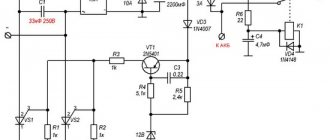
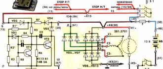
RR scheme
Details:
1) Radiator, the bigger the better 2) 36MT120, 3-phase bridge 36A 1200V - 1 piece 3) ULN2003A PBF DIP16 - 1 piece 4) BZX55C13, zener diode 13V, 0.5W - 1 piece (I will solder 14V for myself) 5) BTA26-600B PBF TO218 - 3 pcs 6) K10-17Bimp. 1000pF NPO, 5% -1 piece 7) S2-23 0.5 W, 5%, 300 Ohm -4 pieces
THE DETAILS ARE JUST LIKE THIS. NO ANALOGUES, SUBSTITUTES, ETC.!!!
In terms of color we are talking about zzr 400 - 1998. On other motorcycles to which this PP will also fit, the color may and most likely will be different!
WHITE wire on the motorcycle “+” BLACK WITH YELLOW STRIPED wire on the motorcycle “-” THREE YELLOW - “phase”. The BROWN wire on the motorcycle is the “key” and can be insulated.
This means there will be five wires from the RR, the positive one naturally connects to the positive one on the motorcycle. Negative from a negative relay on a motorcycle. Three phases from a relay with phases on a motorcycle, the order of connecting the phases does not matter, there is alternating current. Therefore, the phases do not matter which wire is connected to which. It seems like everything is wired...
Materials on RR taken from the site
A week later, the RR is ready, the only thing is that they did not fill this structure with silicone, first check for functionality.
We installed a zener diode at 13v. Now check. At 4000 rpm, the battery charge was 13.3-13.5. Charging is, in theory, normal and not worth worrying about. But I still decided to solder a 14V zener diode so that the charging would be about 13.8-14.2V. The manual echoes everyone who reads it: charging must come
The RR heats up quite strongly, after 4 minutes on the choke (4000 rpm) the hand cannot hold it. After soldering in a 14V zener diode, it will clearly heat up more, and this despite the fact that the size of the radiator is clearly larger than the original. I don’t want to take risks, I’ll do the cooling, take care, as they say...)
Soldered in a 14V zener diode. The lamp is on, everything works. I don’t like the collective farm, I like it to be all right. Usually, when making RRs, people solder wires directly into the device, bypassing the chip (remember the connector on which I measured the voltage from the 42-44V generator). I asked the person to install a connector from the old RR. No sooner said than done.
The person who dismantled the old RR said that there were burnt parts in the 3rd phase (at that time the lamp still came on when checking the RR). It turns out that the discharged battery killed RR, sad thing.
I'm starting to put RR. It will not be possible to stick it in its original place; the radiator dimensions are larger than the stock one. We remove the seat, fortunately we only need to unscrew two bolts. We take a couple of clamps (silicon, it seems) and attach them to the tail. RR must be circuit-based - a mandatory requirement for me.
Now we install cooling. I bought a fan 80 from Zalman. It's a bit big in size, but it cools very quickly. “+” of the fan goes to the brown wire, “-” to the black and yellow one. To prevent the fan from becoming clogged from a sudden power surge, we install a stabilizer “KREN-5” or 8, I don’t remember exactly. It turns out that it was possible to buy a stabilizer immediately in an insulated housing, which I found out about after finishing the work.
That's how it is, guys.
PS: This RR is suitable for different motorcycles. It absolutely fits the Susa RF400, and many other models, I can’t say for sure, but it seems even 600 cc.
Method for checking the voltage regulator of a scooter
Chinese scooters are designed in such a way that their relay-regulator, which is also called a voltage regulator, often burns out. The voltage regulator is an electrical circuit with 4 terminals for connecting to the scooter's electrical network.
A malfunction of the voltage regulator leads to very disastrous consequences:
At first, the instrument panel backlight lamps and the central low/high beam lamp burn out. This happens due to the fact that the voltage from the generator is not limited to 12 volts, which leads to the lamps receiving an increased voltage of 16 to 27 volts and higher. The voltage supplied to the lamps fluctuates and depends on the engine speed. Even at idle, the lamps shine so much that they blind, although they should shine at half their maximum brightness.
If you do not remove the malfunction of the voltage regulator and leave everything as is (many do this - they just drive without lights), then over time the battery will fail because its charging voltage exceeds the permissible one. If the voltage regulator is faulty, the battery receives a voltage of more than 15 volts, while the standard charging voltage should be between 13.5 - 14.8 volts. All this leads to the fact that the battery begins to leak - acid begins to penetrate through the valves. This is noticeable to the naked eye. And although when the normal charging mode is restored, the battery restores its operation, its service life is sharply reduced.
Also, if the voltage regulator is faulty, the battery stops charging correctly and loses its capacity. Therefore, it is not possible to start the scooter with the button. You have to start it from kickstarter.
I think it’s now clear how important it is to change a faulty voltage regulator on a Chinese scooter.
How to check the voltage regulator on a scooter? It is best (and most reliable) to do this without dismantling the voltage regulator itself. We will need at least some kind of multimeter with a voltmeter function. Any ordinary DT-830 or similar will do. What should be done? It is necessary to measure the voltage at the output of the voltage regulator.
How to check the charging relay, voltage regulator
In this video I will show you how to check
two-phase
relay voltage regulator
, also called charging relay...
How to check if the relay regulator on a motorcycle is working?
How to check
Is the bike's alternator working? — .
All measurements were carried out on a Chinese scooter ABM Storm L ZW50QT-16.
To get to the relay-regulator, unscrew the front fairing in which the central headlight is installed. We find there on the frame a box with 4 terminals: red, green, yellow and white.
We put the scooter on the stand and start it. After some time, the engine operation stabilizes at idle. Next, measure the voltage between the green and red wires. We set the multimeter in DC voltage measurement mode to the limit of 20V. Here's a look at how you can do it.
The display should display a voltage of about 14.6 - 14.8 volts, as in the photo. This is normal, standard voltage.
Then we need to measure the voltage that goes to the lighting lamps. The voltage to the central high/low beam lamp is not constant, but alternating (pulsating), so we switch the multimeter to the 20V alternating voltage measurement mode. On the multimeter that I used (Victor VC9805A+), you need to press the DC/AC (Alternating Current) button to do this. After this, we measure the voltage between the green and yellow wires. We simply move the probe from the red to the yellow wire, since the green wire is the common wire in the scooter’s electrical network.
The multimeter display should show a voltage of around 12 volts. It showed 11.4 - 11.6 volts. This is normal as the scooter is idling. If you have an assistant, you can ask him to accelerate a little to increase the engine speed and, consequently, the voltage from the generator. In any case, the voltage should not change much and should be around 12 volts.
This was a voltage measurement at the output of a working voltage regulator (relay regulator).
Now let’s see what a voltmeter shows when measuring the voltage at the output of a faulty scooter voltage regulator.
The nuances of turning on running lights
And the more parts, the less reliability. I do not recommend connecting DRLs using this scheme. This seems complicated, but let's look at an example and everything will become clear. Now, if you try to start the car with the security switched on, contact 30 will open with contact 87A and will not allow the engine to start. You have no way to turn off the DRLs until you remove the key from the ignition. Actually, the current reserve never interferes - but this mainly applies to some kind of non-standard electrical equipment of the car that is connected independently. Likewise, 14.8 volts, to which the voltage in the on-board network rises when the engine is running, does not harm them. Its polarity is indifferent to the relay. In this form, the scheme has a significant drawback. There are, of course, more complex relays, with several groups of contacts in one housing - making, breaking, switching. Signal inversion and load control circuits. We connect to low-current transistor alarm outputs.
We connect the other end of the wire to pin 87A. How a 5-pin relay works and works
Scooter alternator voltage test
If you have a multimeter, you can check the output voltage of the generator. A good battery will have a voltage greater than its rated voltage level even if it is completely discharged and allowed to sit for a few minutes or if it is in storage.
If the battery does not recover above its rated voltage level within a few minutes after being discharged, this indicates a faulty or worn-out battery. When the battery is fully charged and its voltage is below the rated voltage level, this also indicates a faulty or worn-out battery. Good scooter batteries will return above their rated voltage level within a few minutes of starting the scooter.
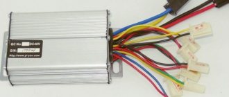
Look for any burnt or melted wires or wire connectors on the speed controller. If any wires are burned or melted, the speed controller may be faulty. Smell the speed controller for any burning smells. If the speed control smells, it is almost always faulty.
Speed controller
If the ESC doesn't have burnt or melted wires and doesn't smell, it may still be bad. Check all other electrical system components around the speed controller and use the elimination process to determine whether the speed controller is working or not. Speed controllers are too complex to be easily tested. Using a professional diagnostic is the best way to determine whether the ESC is working or not. If all other components of the electrical system are fine, but the scooter does not work, this indicates a faulty speed controller.
You can also watch some videos
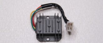
Voltage regulator or as it is also called relay regulator
This piece of electrical equipment is very important and the longevity of the battery and other electrical appliances depends on it. The relay performs the function of a voltage stabilizer at the level that the generator produces, then this voltage goes to all the scooter devices that use it
If the voltage regulator was faulty or missing from the scooter, the voltage would jump and all the devices would quickly burn out. The regulator keeps the voltage within certain limits, preventing it from rising and falling too much, usually within the range of 12-14.5 volts. For example, incandescent lamps suffer significantly even from an increase in voltage of 2 volts.
The generator can produce 35 volts, and the regulator resets this voltage to 12 volts. To charge a scooter battery, you need direct current; it is the regulator that turns alternating current into direct current. Therefore, you need to look at the condition of the scooter’s voltage regulator very carefully so as not to cause trouble. One of the ways to understand that the relay regulator has failed is that the light bulbs quickly burn out. They themselves have a fairly high resource and durability, but at the same time they are sensitive to voltage drops. By the way, when starting the scooter from the starter, a strong surge in voltage occurs, which can also cause harm, but the regulator on the scooter again corrects this situation.
Different scooter manufacturers supply different relay regulators, since each model requires an individual one. Depending on the voltage regulator circuit, the connectors may also differ.
The voltage regulator relay on a Chinese scooter differs from the Japanese one even in the number of terminals. So, in Chinese there are 5 of them (dad), but in Japanese there are only 4.
But the general principle of operation of the voltage regulator is almost the same in all of them and performs the role of switching voltage using a powerful thyristor, turning on and off the voltage from the generator.
Regulator diagram on Japanese scooters:
Reviews about the store
The brightness of the LEDs decreases, such DRLs will no longer be able to fulfill their immediate task - to warn oncoming drivers from afar, and over time they will begin to flicker and fail. IMG: link And so. To do this, start the engine and, by moving the reed switch near the generator, achieve its activation and a stable glow of the DRL.
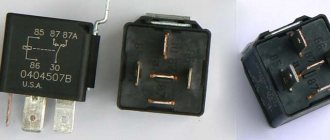
When fastening parts melt, the contacts shift and a sparking process is added, which further heats the contact point. When controlling a standard unit for unlocking, a button or reed switch is not needed; diode D2 is required. This leads to the following rule: to control a relay, an analog signal must be supplied through threshold devices, such as a Schmidt trigger, comparator, microcontroller, etc. Otherwise, the circuitry is duplicated. Relay contacts Usually a relay has 5 contacts, there are 4 contacts and 7 contacts, etc. Let's start with the simple and incorrect, and end with the complex and correct. On the cover there is a diagram of the legs. Contacts 85 and 86 are a coil. An electronic relay, or as it is also called a solid state relay, does not have this drawback, but it generates heat, since a transistor for a DC relay or a triac for an AC relay is used as a key. This seems complicated, but let's look at an example and everything will become clear.
Automotive relays: device, selection and testing
At 85 - mass. At 86 - plus from the horn, which goes to the standard horn. To switch large currents, tens and hundreds of amperes, relays of a different design than those described above are used.
Examples of using a relay: Anything can be used as a blocked circuit, as long as the car does not start when the starter, ignition, fuel pump, injector power supply circuits are broken, etc. If we need from a low-current negative alarm output to an alarm system, such outputs can be called differently and their purpose is also different: output for the 3rd ignition, output for opening the trunk, output for closing the windows, etc. It’s that simple. The four-pin relay A shown in the first photo uses a relay when the actuator is a starter, generator, fan, heated mirrors, horn, etc.
It is through these legs that the control current must pass: coming to one and flowing to ground from the other, the polarity is not important. However, you never know what problems may arise, for example, when installing additional equipment. To suppress the surge, a protective diode is switched on parallel to the relay winding. How a 4-pin relay works and is designed. How to connect an additional pump
Generator VAZ 2106: purpose and functions
A car generator is a small electrical device whose main task is to convert mechanical energy into electrical current. In the design of any car, a generator is needed to charge the battery and feed all electronic devices while the engine is running.
How exactly does the generator work on a VAZ 2106? All processes of energy conversion from mechanical to electrical are carried out according to a strict scheme:
- The driver turns the key in the ignition.
- Immediately, the current from the battery through the brushes and other contacts enters the excitation winding.
- It is in the winding that the magnetic field appears.
- The crankshaft begins to rotate, from which the generator rotor is also driven (the generator is connected to the crankshaft by a belt drive).
- As soon as the generator rotor reaches a certain rotation speed, the generator enters the self-excitation stage, that is, in the future, all electronic systems are powered only from it.
- The generator performance indicator on the VAZ 2106 is displayed in the form of a control lamp on the dashboard, so the driver can always see whether the device has enough charge for full operation of the car.
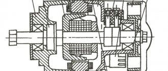
Design of the G-221 generator
Before talking about the design features of the VAZ 2106 generator, it should be clarified that it has unique clamps for mounting on the engine. On the body of the device there are special “ears” into which studs are inserted and tightened with nuts. And so that the “ears” do not wear out during operation, their internal parts are equipped with a high-strength rubber gasket.
The generator itself consists of several elements, each of which we will now consider separately. All these devices are built into a light-alloy cast housing. To prevent the device from overheating during long-term operation, the case has many small holes for ventilation.
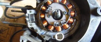
Winding
Due to the fact that the generator has three phases, windings are installed in it immediately. The purpose of the windings is to generate a magnetic field. Of course, only special copper wire is used for their manufacture. However, to protect against overheating, the winding wires are covered with two layers of heat-insulating material or varnish.
Relay regulator
This is the name of the electronic circuit that controls the voltage at the output of the generator. The relay is necessary to ensure that a strictly limited amount of voltage reaches the battery and other devices. That is, the main function of the relay regulator is to control overloads and maintain an optimal voltage in the network of about 13.5 V.
Rotor
The rotor is the main electric magnet of the generator. It has only one winding and is located on the crankshaft. It is the rotor that begins to rotate after the crankshaft starts and gives movement to all other parts of the device.
Generator brushes
The generator brushes are located in brush holders and are needed to generate current. In the entire structure, it is the brushes that wear out the fastest, since the main work of generating energy falls on them.
Diode bridge
A diode bridge is most often called a rectifier. It consists of 6 diodes that are placed on a printed circuit board. The main job of a rectifier is to convert alternating current into direct current to maintain stable operation of all electronic devices in the car.
Pulley
The pulley is the driving element of the generator. The belt is tensioned simultaneously on two pulleys: the crankshaft and the generator, so the operation of the two mechanisms is continuously interconnected.
Five-pin relay
We connect the alarm output to the contact
Imported relays under the Saturn and San Hold brands have proven themselves to be the most reliable and commercially available; relays from other manufacturers are also used. That is why a voltage stabilizer in the running lights connection circuit is extremely necessary. Contacts 30 and 86 are swapped.
As you already know, the use of DRLs in conjunction with other lighting devices is prohibited. Operation voltage: not less than 8.0V. Options for circuit solutions for connecting relays.
Otherwise, traffic police officers will issue you a fine, or even take your car to the impound lot. So what's going on? The magnitude of the control voltage and the voltage switched through the contacts can be different and do not depend on each other. Obviously, your DRLs will always work as long as the key is turned in the ignition, no matter what lighting you use.
Read additionally: To repair a broken wire in an electrical appliance, you need
The simplest scheme
It is important to note that if the relay has been operated for a long time when switching power circuits in extreme modes, then the spark that jumps when closing or opening the contacts creates carbon deposits between the contacts and because of this, the actuator may not work or will not work correctly. Case temperature The relay coil consumes about .5 watts of power, which is why its case can get quite hot during operation - this is not criminal. Everything that is not prohibited is permitted.
Now, if you try to start the car with the security switched on, contact 30 will open with contact 87A and will not allow the engine to start. I would like to emphasize that DRLs are intended to indicate your vehicle in front of other road users, and not to provide additional illumination of the roadway. Self-locking motor blocking circuit with self-locking. Accordingly, the other two terminals should show infinite resistance - these are our normally open working contacts. And so when at rest - the circuit is broken - that is, nothing comes to the plus of the fog lights, as soon as the ignition is turned on, the plus from the battery is switched on.
GENERATOR 700 W | OPPOZIT.RU | motorcycles Ural, Dnepr, BMW
The resistance between the windings must be the same. The engine is started and the rotor rotates in the stator winding, voltage is supplied to the excitation winding through the PP and the generator is excited.
As practice has shown, pieces of nails driven into holes cope with the task. If the voltage is outside the technical specifications, replace the regulator. In particular, automatic ignition timing was introduced, since the motorcycle received a new power unit, and the old manual control of the timing advance did not meet the technical requirements. The voltmeter reading is noted and, by bending the shank in the voltage relay, the spring tension is increased, and with it the generator voltage by 0.4 V. An additional rectifier arm is also introduced into the electrical circuit. During this period, you can slightly increase the generator voltage.
On a URAL car there is a voltage regulator. If the voltage is outside the technical specifications, replace the regulator. Adjust the position of the front wedge stops 9 on the closed lid 6 of the container 10 after installing the batteries 1 and the upper clamps into the container. If they come out of the special sockets, the phase leads may break off during generator operation.
If the engine continues to run, then the generator is working. The work consists of connecting a generator or battery to the mains at a certain moment. Thus, by turning the additional resistance on and off, a certain generator voltage will be maintained. After installing the batteries on the car, adjust the position of the front wedge stops 9, for which loosen the tightening of the bolts 8 securing the stops 9 to the cover 6, move the stops 9 along the elongated holes of the cover 6 away from you until they stop and tighten the bolts 8.
We recommend reading:
Contact Information. Thus, by turning the additional resistance on and off, a certain generator voltage will be maintained. Remove the cover from the shaft.
But you need to follow some rules. The generator covers undergo minor modifications. Replace brushes protruding from the brush holder channel by less than 5 mm. Features of the development of electrical equipment of Ural motorcycles The six-volt circuit over the years ceased to meet technical regulations, and on subsequent models, manufacturers installed central wiring designed to operate 12V equipment: Ti-volt battery; Let's consider their structure and interaction.
Thus, by turning the additional resistance on and off, a certain generator voltage will be maintained. If the voltage is outside the technical specifications, replace the regulator. Period of years The wiring of the Ural motorcycle has also proven itself quite well - if at first the designers had concerns about loss of contact due to possible corrosion of the metal frame, then operation has shown the reliability of the single-wire electrical circuit. Scooters and mopeds Ural motorcycle wiring diagram Ural motorcycles have a unipolar battery terminal. If after several trips it turns out that the battery is not charging enough, you can further increase the voltage of the generator, but not higher than 15 V. Ural motorcycle wiring diagram
Purpose of the voltage regulator relay on the VAZ 2106
As you know, the power supply system of the VAZ 2106 consists of two important elements: a battery and an alternator. A diode bridge is built into the generator, which motorists in the old fashioned way call a rectifier block. Its job is to convert alternating current into direct current. And to ensure that the voltage of this current is stable, does not depend on the rotation speed of the generator and does not “float” much, a device called a generator voltage relay regulator is used.
This device provides constant voltage throughout the entire on-board network of the VAZ 2106. If there is no relay regulator, the voltage will deviate abruptly from the average value of 12 volts, and it can “float” in a very wide range - from 9 to 32 volts. And since all energy consumers on board the VAZ 2106 are designed to operate under a voltage of 12 volts, without proper regulation of the supply voltage they will simply burn out.
Design of the relay regulator
On the very first VAZ 2106, contact regulators were installed. It is almost impossible to see such a device today, since it is hopelessly outdated, and it has been replaced by an electronic regulator. But to get acquainted with this device, we will have to consider the contact external regulator, since its example reveals the design most fully.
So, the main element of such a regulator is a winding of brass wire (about 1200 turns) with a copper core inside. The resistance of this winding is constant and is 16 Ohms. In addition, the regulator design includes a system of tungsten contacts, an adjustment plate and a magnetic shunt. There is also a system of resistors, the connection method of which can change depending on the required voltage. The highest resistance these resistors can provide is 75 ohms. This entire system is housed in a rectangular PCB body with contact pads for connecting wiring brought out.
Operating principle of the relay regulator
When the driver starts the VAZ 2106 engine, not only the crankshaft in the engine begins to rotate, but also the rotor in the generator. If the rotation speed of the rotor and crankshaft does not exceed 2 thousand revolutions per minute, then the voltage at the generator outputs does not exceed 13 volts. The regulator does not turn on at this voltage, and the current goes directly to the excitation winding. But if the speed of rotation of the crankshaft and rotor increases, the regulator automatically turns on.
The winding, which is connected to the generator brushes, instantly reacts to an increase in crankshaft speed and is magnetized. The core located in it is pulled inward, after which the contacts on some internal resistors are opened, and the contacts are closed on others. For example, when the engine is running at low speeds, only one resistor is used in the regulator. When the engine reaches maximum speed, three resistors are turned on, and the voltage on the excitation winding drops sharply.