The Solex carburetor (DAAZ) is one of the most popular devices in the list of carburetor metering systems, since with the right approach it is possible to flexibly configure carburetors of this type. For this reason, car enthusiasts install Solex carburetors on different engines, after which they are further adjusted, achieving the required fuel efficiency indicators, quality of mixture formation at power and other operating modes of the internal combustion engine.
We also recommend reading the article on how you can do carburetor tuning yourself. From this article you will learn about various ways to independently modify carburetor metering systems.
After installing Solex on the engine, it is often necessary to configure this device. To solve the problem, you can contact a service center, where a specialist in setting up the carburetor will perform all the necessary operations. You can also adjust the carburetor yourself. In this article we will talk about how to adjust the quality of the mixture on a Solex carburetor, how to adjust the fuel level and adjust the float chamber of the Solex carburetor, adjust the idle speed, etc.
Solex carburetor: setting and adjustment
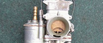
Before starting the setup work, if it is necessary to adjust the carburetor air damper, the fuel level in the chambers, setting the idle speed and other manipulations, it is necessary to separately study the design of the carburetor system, the location of the jets and other basic elements (econostat, economizer, float, first and second chamber, dampers, etc.) You should also pay attention to how the cover is removed and the carburetor is disassembled.
We also recommend reading a general article about the structure and principle of operation of a carburetor. In this article you will learn about the main components of a mechanical dispensing device.
You need to start setting up by setting the fuel level in the float chambers. The recommended method is to set the specified level according to the position that the floats have in relation to the carburetor cover. All manipulations are carried out using a separate template. Note that, as practice shows, this method cannot in any way be considered optimal, since when installing Solex on a car, it should be taken into account that the fuel pump on one specific vehicle may differ from the fuel pump on another car. There may also be other differences in the power supply system. The result is that the pressure on the carburetor needle (carburetor shut-off valve) is also different. Most often, after tuning according to the template, fuel enters the carburetor in large excess. In order to accurately set the gasoline level in the carburetor and adjust the Solex carburetor float successfully, you must follow the steps described below.
- Usually, immediately after installing Solex on different internal combustion engines with different displacements, even without preliminary adjustments, the engine should still start. The engine must be started, after which the power unit should run for about 10 minutes. When running at idle, you can lightly press the gas and increase the speed to avoid the engine shooting into the carburetor or exhaust system.
- Then the power plant can be turned off, after which it is necessary to remove the fuel supply hose. It is recommended to prepare a rag to remove any remaining gasoline that splashes after removing the said hose. The hose is removed so that after removing the carburetor cap, gasoline, which is under pressure in the hose, does not spill into the carburetor chamber. In other words, excess fuel entering the chamber can interfere with the accuracy of the measurements.
- Now you can unscrew the screws securing the carburetor cover, then you need to remove the cable that controls the “choke”. The next step is to carefully lift the carburetor cover. The specified cover should be lifted in a strictly horizontal position so as not to cause damage to the floats themselves.
- Next, you should prepare a ruler or caliper.
With these tools you need to measure the distance that is obtained from the fuel itself in the chamber to the adjacent surface of the carburetor cover. The indicated distance from the surface of the cover to the surface of the fuel should be about 2.5 cm. We add that the distance must be measured in both chambers. This distance may vary, taking into account that the collector is not in a strictly horizontal position. Based on the difference in distances in both cameras, an average value is selected. If the fuel level is insufficient or exceeds the required level, then the tongue of the floats must be very delicately bent for less or more filling. Then the excess gasoline must be removed from the chambers to more accurately determine the level obtained after adjustments at the next measurement. The carburetor should be assembled, after which the engine starts again. - After the engine has been started, it is necessary to illuminate the carburetor chambers with a test lamp or flashlight, observing the small diffusers. During the period from 30 seconds to 1 minute, fuel should not drip from the diffusers. If you notice even a small drop, then this indicates that there is an overflow in the chamber. Please note that you cannot accelerate while observing the diffusers; the engine should only run at idle. The fact is that an unexpected shot or sneezing into the carburetor while applying gas can lead to eye injury.
If no drops of fuel were noticed, then all that remains is to re-measure the fuel level in the chamber using the already known method. If the result is positive, this part of the setup can be considered complete. If the level again differs from the norm, then the level should be adjusted again. Note that setting the level with the engine turned off during manual pumping is not correct, since after starting the internal combustion engine the carburetor will still overflow, especially on engines where the return line has been blocked.
Solex carburetor: idle speed adjustment
The next step after adjusting the fuel level in the carburetor float chamber is to adjust the idle speed. To set up, you must first warm up the engine until it reaches operating temperature. After warming up, the unit should be turned off.
At the very beginning, you need to find the air-fuel mixture quality screw, which is rotated using a flat-head screwdriver. The specified screw is located in the hole, which is made in the lower part of the carburetor.
- The quality screw must be tightened until it stops. Screwing is carried out clockwise, and there is no need to apply force, as the thread can be damaged. After the screw stops, you should turn it back from the stop position by 4-6 turns.
- Now the engine should be started, the choke should be removed. Then you should set the minimum permissible speed by turning the quantity screw. Such minimum speed can be considered an indicator when the engine operates stably and steadily. Also, the vacuum in the vacuum advance fitting should be minimal. A fairly simple way to determine the vacuum is to close the tube that goes into the so-called vacuum advancer with your tongue. If the idle speed is in the range from 600-1200, the carburetor is fine.
- Next, the quality screw must be slowly tightened until the operation of the unit begins to lose stability. As soon as the engine begins to operate unstably, you should unscrew the screw back one or one and a half turns, catching the position when the motor is operating stably again
- We return again to the quantity screw, with which the idle speed should be set to 800-950 rpm. We set the speed screw at XX to about 850-900. If the engine stalls when setting such speeds, then you need to unscrew the quality screw.
- The quality and quantity screws are adjusted until the required idle speed is set, the vacuum in the advance tube will be minimal, and the internal combustion engine itself will be able to operate stably.
Please note that during the setup process you may encounter certain difficulties. For example, the operation of the engine may not change in any way when trying to tighten the quantity screw (normally, the speed should drop, the engine starts to run unevenly, then stalls as the screw is tightened). If this does not happen, then a large amount of fuel enters the idle channel, which cannot be blocked by the quality screw.
This problem arises for a number of reasons. First of all, a large idle jet can be installed. You should also pay attention to how tightly the solenoid valve or plug is screwed in. If the fit is not tight, excess gasoline may be sucked in bypassing the idle jet. Also, one should not exclude possible problems with the jet itself, as well as with its seat. To more accurately understand the reason, you will need to remove the solenoid valve wire with the engine running and idling. In this case, after removal, the unit should quickly stall. If this is the case, then the cause is most likely a large idle jet. The solution will require installing a smaller jet.
If the engine does not stall after removing the wire from the valve, then this problem may arise as a result of gasoline overflowing into the float chamber. It is also possible that when the internal combustion engine is running, fuel bypasses the jet or even the entire idle system. First of all, we again check that the level in the float chamber is set correctly. If everything is normal with the level, then the solenoid valve/plug should be unscrewed, after which you need to inspect the nozzle and its installation location. There should be no defects. If there are any, then the carburetor cap may need to be replaced. If no defects are found, then the jet is put on the valve, the O-ring is lubricated with engine oil, after which it is tightened with a wrench without effort.
Lean mixture: what is it?
A poor fuel assembly is a fairly common problem. It leads to significant problems in the engine and serious malfunctions. Of course, such a mixture, like an over-enriched one, is considered a deviation from the norm, because the amount of air in such a mixture is off scale, and the amount of gasoline is not enough. From such a mixture, the engine constantly smokes, overheats, loses power, etc.
The consequences can become even more severe if a lean mixture is constantly supplied to the cylinders. The spark plugs will signal this with a white coating, misfires will begin, overheating and burnouts will occur, and the pistons may even melt.
Adjusting the quality of the fuel mixture
It is noteworthy that a lean fuel assembly is always a change in the recommended ratio of 1x15, which is considered the most optimal. The fuel assembly obtained in this percentage ratio is called stoichiometric; it allows the car’s power plant to reach its best performance.
As soon as the amount of air in the fuel assembly increases, the charge becomes depleted. This reduces fuel consumption, but significantly reduces power.
Jets and accelerator pump
Owners of carburetor cars know that jets change, but they do not always understand why jets are needed and how their size affects the operation of the carburetor. Let's start with the fact that the engine sucks in air through a special hole made in a large diffuser. At the same time, a certain amount of fuel is drawn through the fuel nozzle. The engine displacement directly affects how much air the engine will draw through the diffuser in a certain time, as well as the amount of gasoline sucked in parallel with the air.
It is for this reason that large-volume engines have carburetors with small jets. Installing such a carburetor on an engine with a smaller volume will mean that the “original” jets in this carburetor will produce a mixture that is too lean for normal engine operation. To solve this problem, you should find jets from a carburetor, which was initially designed for a specific internal combustion engine volume or as close as possible to it. You need to select jets starting with the fuel jet, then select the air jet under the fuel jet. The selection is made from a group of jets for the first chamber, the second chamber is adjusted only after the first.
Now let's talk about the accelerator pump. The accelerator pump delivers additional fuel when the throttle valve opens, allowing for more efficient acceleration. The pump is activated using a special cam. On engines with a Solex carburetor installed, the indicated accelerator pump cam must be set to the largest one.
You should also pay attention to the so-called “spout” of the accelerator pump. When the valves are opened, fuel should flow in a clear stream and not drip even with a slight throttle opening. It is also important what position the nose occupies. The stream of gasoline must fall exactly into the area between the diffuser wall and the throttle valve, that is, the fuel is jetted directly into the manifold. The jet must not hit the diffuser or damper. If this happens, then after sharply pressing the accelerator pedal the car will not accelerate immediately, and a failure will occur. Self-refinement of the carburetor involves installing two spouts in the chambers to obtain better performance from the engine, or only one spout in the first chamber of the carburetor for a more economical mode.
Nozzle design for four-stroke engines
The design described below is currently also widely used for two-stroke engines, as it allows one to obtain a leaner and more homogeneous mixture in all modes.
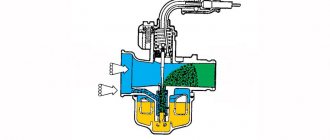
The body of the four-stroke type atomizer is equipped with rows of holes, and the annular chamber that surrounds it is constantly in communication with the atmosphere, but does not communicate directly with the diffuser. This allows the fuel to begin mixing with air before it reaches the diffuser, forming an emulsion inside the atomizer. With this design, the nozzle atomizer has no protruding part into the diffuser.
The operating principle of the main dosing system with a four-stroke type sprayer is shown in the figure. The holes in the lower part are immersed in fuel, since they are below its level. The holes in the upper part are always open for air to pass through. When holes in the top portion predominate, the mixture becomes leaner, while increasing the number and/or diameter of holes in the bottom portion results in increased fuel consumption with intense emulsification. Due to the location of the holes throughout the entire area of the nozzle, the annular chamber, initially filled with fuel, becomes empty as the speed increases, since the fuel is consumed through these holes, which leads to an over-enrichment of the mixture at the beginning and to its depletion in the future.
Operation of the main dosing system with a four-stroke type atomizer: Fuel rises from the float chamber along the atomizer 5, passing through the nozzle, which, together with the needle 3, regulates the fuel consumption. The fuel is initially mixed with air passing through channel 2 in the annular gap between the nozzle and the body. The emulsion is mixed with air entering through the inlet device 1 in the diffuser and mixing chamber 4.
Simply put, the location of the holes in the nozzle body and their diameter significantly affect the flow of fuel and the engine response that depends on it. Thus, by varying the parameters of the holes, it is possible to achieve the optimal mixture composition for all operating modes.
Carburetor transition setting
While the engine is idling, the throttle valves are closed. A vacuum (vacuum) is formed under the dampers. Thanks to this vacuum, gasoline is sucked out through a small idle channel and nozzle, and the engine itself runs smoothly at idle. If you open the damper sharply, then the vacuum also weakens. Moreover, this vacuum is not enough for normal operation of the MDS (main dosing system) in the first chamber, and the idle system and accelerator pump are not yet capable of normalizing engine operation. In other words, when you sharply press the gas after idling, there is a delay in the response to pressing the accelerator pedal.
To minimize or completely eliminate this failure, a transition system is used in the carburetor device. This diagram is a hole-slot made above the throttle valve in the first chamber. At the moment you press the gas pedal, the slot-shaped hole appears in a zone of high vacuum, due to which intensive fuel suction occurs parallel to its supply through the idle jet.
Let's go back to the settings. After the carburetor has been installed, many cars experience a failure when starting from a stop, reactions to pressing the gas pedal are slow, and the engine may start shooting at the carburetor or stall. In such a situation, the transition system may be to blame. In order to normalize the operation of the carburetor, it is necessary to correctly select the cross-section of the “spout” of the accelerator pump and the size of the idle jet.
The fact is that it is during operation in the transition mode that fuel comes from both the accelerator pump and the transition system. As a result, the fuel-air mixture may become too rich or, conversely, lean, which does not allow the engine to operate normally and gain speed.
It is important to know that the nozzles in the first chamber do not need to be touched, and the indicated failures should not be attempted to be eliminated by replacing the nozzles of the main dosing system. To solve the problem, use a previously built carburetor to correctly select the idle jet and the accelerator pump spout. The selection must be made after the internal combustion engine has warmed up, the choke must be removed.
In practice it looks like this:
The level in the float chamber was previously set and the idle speed was adjusted. A warm engine idles normally without chugging. A stream of gasoline from the accelerator pump nozzle hits the manifold. Now you can sharply press the gas pedal. What is needed is the sharpness of the press, and not how hard the pedal was pressed (to the floor, half a stroke or ¼). Normally, the motor should immediately respond and spin up, that is, the speed increases without delays or failures. If the response to a sharp press on the accelerator is slow or there is a noticeable pause before the speed increases, then you should go to the settings.
To accurately determine the cause, you need to press the gas pedal again, but this time smoothly and not sharply. If in this case there is an even increase in speed (without pauses, dips or delays), then you should pay attention to the idle jet and the pump spout, since the main dosing system has nothing to do with the failure. If, when you gently press the gas, the engine spins up poorly, the unit itself begins to work jerkily, hums, vibrates strongly, etc., then the problem lies in the selection of jets for the first chamber. In other words, excessive enrichment or leanness of the mixture occurs after the carburetor switches to power mode after pressing the accelerator. An indirect sign of a too “rich” mixture during operation in transition mode is that the engine emits black smoke and the smell of gasoline comes from the exhaust system. The specified smoke and smell appear after sharp throttling.
To remove the dip, you must carefully select the idle jets to match the pump spout or vice versa. This is done until the delay disappears when you sharply press the accelerator pedal. In parallel with this, it may be necessary to re-adjust the idle speed, since replacing the XX jet will make changes to the operation of the idle system. Let us add that if the mixture remains lean and there is a dip, and the idle jet is too large and it is not possible to adjust the idle speed, then you can install a paired pump spout, after which both tubes are bent into the first float chamber.
Main dosing system sprayer
The simplest atomizer is a tube connecting the main fuel jet to a diffuser. Engineers conventionally divide sprayer designs into “two-stroke” and “four-stroke”. Some nozzles (called the four-stroke type) have rows of holes around the perimeter, drilled all the way through into the main fuel well.
Sprayers differing in the design of emulsion tubes
Nozzle design for two-stroke engines
The nozzle is screwed into a nozzle (Generally speaking, a hydraulic nozzle is a short pipe for releasing liquid into the atmosphere or flowing liquid from one reservoir to another, also filled with liquid), fixed in the carburetor body.
Pairing the sprayer with the nozzle
As can be seen in the figure below, at the junction of the sprayer and the nozzle, an annular slot is formed, which turns into an annular cavity. The cavity is connected to the atmosphere through an additional air channel. This allows air to enter the diffuser through the annular slot. If the atomizer has holes for emulsifying fuel, air is also supplied to it through an auxiliary channel.
Annular gap between sprayer and nozzle
The inlet of this channel is usually located in front of the diffuser in its inlet part (under the letter b
in the figure below).
The hole next to it is the idle air duct. Sometimes, to reduce the influence of pressure pulsations in the intake receiver, the auxiliary channel communicates directly with the atmosphere. For example, as shown in the picture under letter a
, through the tube on the right side of the carburetor.
Methods for communicating the auxiliary air channel with the atmosphere
In total, the main dosing system works as follows. Under the influence of vacuum, the fuel rises through the nozzle. The flow of fuel is regulated by a jet and a metering needle. Part of the air passes through an additional channel and enters the annular cavity. As a result, intense mixing of fuel and air occurs in the area above the annular slot and the nozzle.
Operation of the main dosing system with a push-pull type atomizer: Fuel from the float chamber rises along the atomizer 6, passing through the nozzle 7, which, together with the needle 3, regulates the fuel consumption. The fuel is initially mixed with air passed through channel 2 in the annular gap between nozzle 5 and the atomizer. The emulsion enters the diffuser 4 and is mixed with air entering through the inlet device 1.
Along with the diameter of the atomizer, the adjusting parameter is the diameter of the air channel (the larger it is, the poorer the mixture), as well as the height of the protrusion of the atomizer and the nozzle into the diffuser. Options for sprayers and nozzles are presented in the figures below.
Sprayers varying in height
Various nozzle options
Let's take a closer look at the atomizer.
Under constant other conditions, the less the atomizer protrudes into the diffuser, the lower the height the fuel needs to rise from the float chamber, which contributes to an earlier start of the process of fuel atomization in the diffuser. The "low" spray is a characteristic feature of sports carburetors. On the contrary, with a high atomizer, the fuel mixture will be leaner in transient (unsteady) conditions.
The same physical principles apply to the operation of an air nozzle. Its protrusion into the diffuser creates resistance to the air flow, so a zone of strong vacuum is created behind the protrusion, which contributes to the flow of fuel. In other words, the higher the nozzle, the greater the vacuum behind it and the richer the mixture becomes. You can lean the mixture using a carburetor with a low nozzle height.
Adjusting the second chamber of the Solex carburetor
Let's start with the fact that when adjusting the carburetor, the second chamber is usually not touched, since often standard jets will be sufficient. The carburetor also has an econostat that can correct possible nuances. The econostat is a tube located in the second chamber at a slight angle.
The purpose of the econostat is that when the throttle is fully opened, the vacuum in the carburetor allows fuel to be sucked through the econostat. The econostat is activated when the engine is running at high speeds and allows the fuel-air mixture to be enriched. To refine the second chamber, which allows for “pick-up,” jets are installed to enrich the mixture. The selection of jets in this case is no different from the selection for the first chamber.
Messages [20]
1↑ Topic from PATRIOT 03/25/2013 14:32:03
- PATRIOT
- Patriot IMZ
- Inactive
- Name: Ilya
- From: Krasnodar region, Krasnodar
- Registered: 18-02-2011
- Messages: 3 148
- Reputation: 177
- Motorcycle: No. Next will be the K750!
Topic: Carburetor adjustment (mixture quality) for beginners!
I think once again it will be useful for beginners to read about adjusting the quality of the mixture, and even the carburetor itself. As already noted, the quality of the mixture at different crankshaft speeds is adjusted differently:
for small ones, use the “quality screw” of the idle speed system;
at medium - with a throttle needle;
at maximum - with the main fuel jet.
Before proceeding with the adjustment, it is necessary to determine the quality of the mixture in various modes by external signs of engine operation. Signs of working on a lean mixture are popping sounds in the carburetor, a drop in power (deterioration of throttle response, drop in maximum speed). Signs of running on a rich mixture are black smoke from the exhaust at maximum speed, popping noises in the muffler, and poor engine response.
In addition, the quality of the mixture can be determined by the color of the spark plug insulator:
with normal mixture quality, the color of the insulator is brown,
with a lean mixture, the color of the insulator is whitish-gray or light brown,
with a rich mixture, the color of the insulator is dark brown or black.
Carburetors are adjusted on a warm engine. If the carburetor is adjusted on a cold engine, then when the engine warms up, it will be disrupted, since the volatility of gasoline in contact with heated parts will change and the quality of the mixture will change accordingly.
The left and right carburetors are adjusted separately. To do this, place the motorcycle on a stand and start the engine (to facilitate starting on two cylinders). On the carburetor cylinder that is not being adjusted, remove the tip from the spark plug and short it to ground. If the tip of the spark plug is not connected to ground, the process of spark formation in a working cylinder will be difficult, especially with discharged batteries. In this case, the engine will operate at an increased speed and the carburetor adjustment will be inaccurate. Next, you need to make sure that there is a gap between the cable sheath and the stop on the carburetor. If there is no gap, ensure it by screwing in the stop.
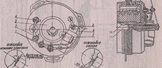
Then adjust the mixture quality at idle. To do this, you need to unlock the idle quality and quantity screws. Screw the “quality screw” 22 (Fig. 5.4) all the way and use the “quantity screw” to set the minimum stable crankshaft speed. Then slowly turn out the quality screw. In this case, the over-enriched mixture begins to become leaner, but will still be rich. When the mixture composition corresponds to the norm, the rotation speed will increase.
As you further turn out the quality screw, the mixture will become leaner, the rotation speed will not increase, and if the mixture becomes too lean, popping noises will appear in the carburetor, so during the adjustment process, turn the quality screw out until the rotation speed increases. It is difficult to determine from the first time at what position of the quality screw the increase in rotation speed stops, so it is advisable to repeat the adjustment operation 2 - 3 times. Turning out the screw, notice when the increase in rotation speed stops. Having finally established the required position, lock the screw. After adjusting the quality of the mixture at idle using the quantity screw, reduce the engine crankshaft speed to the minimum stable speed. After one carburetor has been adjusted, the second one must be adjusted in the same way. Then, with the engine idling, you must alternately remove the caps from the spark plugs of the left and right cylinders and check by ear whether the crankshaft rotation speeds are the same when operating on the left and right cylinders. If the frequencies are not the same, then you need to use the quantity screw, increasing or decreasing the rotation speed, to restore the balance.
This is interesting: How to disassemble a bicycle fork with a shock absorber
After adjusting the quality of the mixture at idle, adjust the quality of the mixture at average speed. But first it is necessary to check the quality of the mixture by sharply “opening” the throttle. If at the same time popping sounds appear in the carburetor or “dips” in engine operation (flashes in the cylinder stop; at the same time, if the throttle is “opened” smoothly, the engine gradually picks up speed), then the mixture is lean. If the engine speed begins to increase slowly, the mixture is rich, if quickly, the quality of the mixture is normal.
The quality of the mixture at average speed is regulated by the throttle needle. If the mixture is lean, you need to move the needle lock to a lower groove so that the needle rises. If the mixture is rich, you need to lower the needle, move the lock to a higher groove.
Setting up the float mechanism
The level of the fuel mixture in the float chamber is directly related to its quality. At an increased level, the mixture will turn out to be lean, which will negatively affect gasoline consumption and increase toxicity. Without adjusting the floats, the question of how to adjust the carburetor cannot be solved. The process of adjusting the floats includes the following operations:
- Adjusting the floats in relation to the lid and walls of the fuel chamber. If deformation of the float fixing bracket is noticed, it should be aligned manually;
- We adjust the bracket with the needle valve closed;
- We adjust with the float retracted and the valve open; the distance between the float and the valve should in this case be set to about 15 millimeters.
Adjusting the carburetor draft
Before you begin adjusting the rods, you should remove the air filter cover so that nothing interferes with the process. First, using a caliper, measure the distance between the rod tips. According to factory parameters, it should be 80 millimeters. To adjust the length of the rods, you need to loosen their clamps.
Checking the strainer should be carried out when there is fuel in the float chamber. This will help you see if the shutoff valve is closing completely. After examining the valve, you need to clean and dry it. Problems with loss of power and engine failures occur due to obstructed fuel supply. This is another reason to thoroughly flush the carburetor.
The tightness of the shut-off needle can be checked using a rubber bulb, while listening for air leaks. If they are present, it is time to change the needle.