Introduced in the 70s, the JAWA family of motorcycles represented a completely new concept in a two-wheeler.
Although, at first glance, all the parameters of the motorcycle are standard - the electrical wiring of the Java 350, the engine operating diagram and electrical systems have been encountered before on other models, including domestic ones.
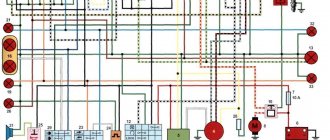
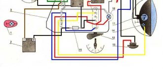
Factory wiring diagram for Java 350 model 1976
how to assemble an ignition lock java 638 YouTube
1 year ago
The easiest way to assemble and repair/restorate the ignition switch Java 638/634 (Gvozdik). Quick repair...
1 year ago
Link to my channel: https://www.youtube.com/channel/UCDJ4OlmeqgxE8zx6b3K0E-g?view_as=subscriber.
5 months back
Ignition switch JAVA 350, 638, 639, 640 (12V) JING, Article: N-2463, review, measurements. More information and current price for...
2 months back
Hello everyone, at the request of a subscriber I made this video. Maybe someone who doesn’t understand motorcycle wiring diagrams...
5 years ago
Java castle is an old lady, For those who have taken it apart and don’t know how to put it back together correctly.
1 year ago
It's time to finish the wiring since the standard Ural lock was used to repair another...
5 months back
JAVA steering lock, A story on how to remove the JAVA 634 steering lock without a key.
12 months back
JAWA lock, JAWA 360 seat lock repair video.
1 year ago
VK: https://goo.gl/aVq38U moto2: https://goo.gl/4na4SA instagram: https://goo.gl/0DlCTy JAVA motorcycle electrical equipment, Java wiring. ...
12 months back
Music / Music in the video: 1. NIPPER - Music for video ▻I'm on VK: https://vk.com/id400345486 ▻My partners: 1.
11 months back
My JAVA 350 638 burned out? Lesson for life! Group in VK - https://vk.com/club151996595 I'm in VK - https://vk.com/id424508073.
3 years ago
One way... if you know better, please share.
2 years ago
THE WHOLE RANGE AND THE LARGEST, WIDE SELECTION OF QUALITY, ORIGINAL SPARE PARTS FOR JAWA MOTORCYCLES 6V, 12V,…
3 months back
A simple solution to the java seat lock problem without a key.
syoutube.ru
Features of the package
The motorcycle was supplied to the USSR in several modifications:
- “JAWA 250” model 559-07 - option with 6V equipment and a 250 cc engine with 12 hp. Produced since 1969;
- “JAWA 350” model 634-04 - option with 6V equipment and a 350 cc engine with 16 hp. Produced since 1973;
- "JAWA 350" model 634-08 - version with 12V equipment on 16-inch wheels. Produced since 1977;
- “JAWA 350” model 638 is the last of the models supplied to the USSR. It was produced since 1986 and was distinguished by wheels increased to 18 inches and a different frame shape.
The price of a used Java was 2 times higher than the price of a new domestic motorcycle
Power supplies for electrical equipment
A special feature of the Czech motorcycle was a generator, which made it possible to operate the Java without a battery. Its design included a method of exciting an electric current sufficient to supply a spark when the engine starts.
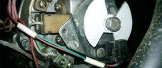
Factory black and white instructions - main generator components
In the diagram presented, the numbers indicate:
- JAWA generator stator;
- breaker lever;
- electronic voltage regulator;
- relay-regulator panel 4-terminal;
- capacitors 2 pcs. - for each cylinder.
For reference: the generator was a system of insulated radial lamellas. Inside the stator there were coils and a rotating rotor with a winding. During the rotation process, a magnetic field was formed in the excitation winding, and the alternating current was converted into direct current through an electronic converter.
Accumulator battery
Along with the new motorcycle, a 14 Amp-hour alkaline battery was included.
Its peculiarity was that:
- The battery was supplied in a dry charged state;
- Before operation, it was required to fill it with electrolyte;
- It was recommended to charge the battery for 5-6 hours before starting work.
In practice, everything happened differently:
- The happy owner brought ready-made electrolyte with him to the store;
- I filled the battery containers with it;
- ;
- Exploited (drove home).
For reference: the additional battery charge recommended by the manufacturer is needed to ensure that the lead plates are saturated with electrolyte under the influence of electric current. Thanks to this, the battery life increased to 4-5 years, while violation of this recommendation shortened the service life to 1-2 years.
How to Assemble the Ignition Switch Java 638
Egnition lock
ignition switch java 638
java seat lock
egnition lock
partsjawa jawaparts java jawa stainless steel java java luxury
MOTOR OPERATION
TOLIK SOROKIN
how to assemble a java 638 ignition switch
how to assemble a java ignition switch
connection diagram
how to repair ignition switch java
Java ignition switch assembly
java ignition switch diagram
how to make ignition switch clicks in java
ignition switch java 634
ignition switch diagram
how to connect ignition switch java
Java ignition switch repair
repair ignition switch java
assemble a java ignition switch
Assembling the Java Castle
Java assembling a castle
buy spare parts
Viper scooter parts
buy spare parts for a scooter
buy spare parts for Honda scooter
scooter spare parts
scooter parts
sale of motorcycle parts
scooter parts 50
buy motorcycle parts
motorcycle parts store
inexpensive motorcycle parts
fitweb.me
Ignition switch Java 638 | Fitweb
Egnition lock
buy spare parts
scooter spare parts
inexpensive motorcycle parts
scooter parts
motorcycle parts online store
scooter parts 50
Viper scooter parts
buy spare parts for Honda scooter
buy spare parts for a scooter
sale of motorcycle parts
motorcycle spare parts internet
buy motorcycle parts
motorcycle parts store
ignition switch java 638
java seat lock
with your own hands
partsjawa jawaparts java jawa stainless steel java java luxury
MOTOR OPERATION
TOLIK SOROKIN
how to assemble a java 638 ignition switch
ignition switch java 634
connection diagram
how to repair ignition switch java
how to make ignition switch clicks in java
ignition switch diagram
Java ignition switch assembly
fitweb.me
- Ignition switch Java 638
BMW E38 ignition switch- UAZ 417 ignition adjustment
- Ignition coil control key
- BMW E38 ignition switch
- Goetz replacing spark plugs
Hyundai Tussan ignition switch- Ford Sierra ignition switch
- Ignition coil 2141 Moskvich
- Ford Sierra ignition switch
- Ignition coil 2141 Moskvich
Thanks to the introduction of a 12 V power supply system with a 14 V 15 A generator (i.e. 210 W) on the Java-638 motorcycle, its power is sufficient not only to cover the electricity needs of all consumers on the motorcycle, including the trailed stroller, but also Also, its power reserve allows you to power other consumers, for example, an additional fog lamp, etc.
All elements of the power supply system are manufactured using modern technology and achieve high power and reliability. To prevent damage to them, Java-638 motorcycles should be operated only with a securely connected battery, which cannot be disconnected from the motorcycle’s electrical network while the engine is running. The battery, permanently connected to the synchronous generator (via the “+B” terminal of the rectifier), with its capacity absorbs all voltage peaks that occur in the secondary stator circuit, which in size can be many times greater than the maximum permissible blocking voltage of semiconductor elements and damage them. These voltage peaks occur on the same principle as engine ignition - a spark created by the energy of the spark plug. Under the load of the generator, electric current flows through the coils of the stator winding. As a result of its sharp decrease (by turning off some of the consumers) or even complete cessation (disconnecting the battery if the consumers are turned off), the energy of the electromagnetic field of the coil causes a voltage in the coil by reverse induction, the size of which is directly proportional to the rate of decrease or attenuation of the current and its size. If electric arc welding will be performed on the motorcycle (various types of repairs, improvements, etc.), then before this all wires from the regulator and rectifier should be disconnected.
The following fundamental recommendation regarding the selection of the maximum current of the generator is 15 A. This power can be selected according to the technical conditions of the generator, provided that the temperature of the stator winding does not exceed 155°C. In practice, this means that for a Java-638 motorcycle, including a trailed sidecar, for which a continuous generator power of 12 A is quite sufficient for permanently or temporarily switched on consumers, it is possible to connect another consumer with a power of up to 42 W (i.e. 3 A) for a long time maximum ambient temperature 30-40°C. When using the maximum generator output of 15 A at higher - tropical temperatures exceeding 40 ° C, thermal damage to the stator winding or the insulation of connected wires and connections may occur, particularly when the motorcycle is running at low engine speed and the generator is operating at low engine speeds. characteristic (see Fig. 1) does not yet develop full power.
Rice. 1. Characteristics of a generator with a rectifier in a heated state at an ambient temperature of +20°C
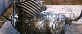
Now let’s look in more detail at the individual elements of the 12 V power supply system. The generator used on the YAVA-638 motorcycle is a three-phase synchronous generator with independent excitation from the battery (i.e., with a six-diode circuit) and a separate rectifier. It consists of a rotor and a stator, and the way it works is similar to how car alternators work.
Rice. 2. Three-phase generator 12 V motorcycle Java-638. The arrow shows the direction of rotation
The rotor is a rotating electromagnet formed by an excitation winding (connected by its contacts to two slip rings), which is wound on a magnetic mild steel core - the core simultaneously represents the rotor axis. It is equipped with an internal cone with a cutout to fit onto the crankshaft. At the other end of the core, in a cylindrical hole, an ignition interrupter cam is installed, the same as that of the generator. The field winding, compressed on both sides between the star-shaped frontal surfaces of the rotor, is impregnated with polyester resin. The magnetic flux generated by the passage of current through the field winding passes through the air gaps between the individual protrusions of the opposite frontal surfaces of the rotor in such a way that its lines of force extend beyond the perimeter of the rotor and, therefore, pass through the stator sheet steel. When the excited rotor rotates, its magnetic field crosses the perpendicular wires of the stator windings, in which an electric current is thus generated by electromagnetic induction. This arrangement of the field winding and the secondary (stator) winding, such as the generator has, produces an electric current with a much higher efficiency already at a lower speed than that of the old 6 V generator - 10.7 A. Therefore, the generator can develop a much higher power than a similarly sized DC generator. The recharging start speed is also lower than that of a DC generator, which allows you to recharge the battery already at engine idle speed when the motorcycle is moving without the headlights on.
The generator stator is a bundle of welded sheet steel with grooves on the inner perimeter in which insulated coils of a three-phase operating winding are installed. The windings of all three phases at one end are combined into a common unit (the so-called star connection), which is output to terminal “86” of the four-pole terminal block and its voltage is controlled by the recharge signal lamp relay. The opposite ends of the windings of the individual phases are individually connected to the “X”, “Y”, “Z” terminals of the four-pole terminal block located in the upper part of the stator casing (when looking towards the generator installed on the engine).
The stator housing is a high-pressure precision casting of aluminum; The stator is hot pressed into the casing. In the middle of the stator casing there is a main breaker board, which differs from the breaker board on the YAVA-634 DC generator only in the size of the 6.3 flat plugs and the longer length of the wires of the connected capacitors. On the right side of the stator casing there is a brush holder made of plastic that is resistant to elevated temperatures. It contains two brushes, pressed by springs to the rotor slip rings; Copper Litz wires connect the individual brushes to the external connection terminals in the form of a 6.3 flat plug, marked "DF" and "I" (ground). The holder with brushes is designed to supply excitation current to the rotor. This is practically the only component of a synchronous generator that is recommended to be checked after a run of about 10 thousand km, namely the degree of wear of the brushes and the possibility of their free movement in the holder. For ease of control of the brushes, a cutout is provided on the side of the stator casing, which allows, after unscrewing the mounting bolts, the holder with brushes to be pulled out of the generator without the need to remove the breaker board and thereby cancel the fine adjustment of the ignition timing. When subsequently installing holders with brushes on a synchronous generator, it is recommended to use the holes in the lower part of the holder under the wire fuse. By first inserting the brushes into the holder and threading a wire approximately 50 mm long through the holes, it is easier to install the holder with brushes and prevents the possibility of breaking the brushes, which otherwise could get stuck behind the edge of the slip rings and break when the holder is pulled to the generator casing. When installing the holder with brushes fixed in this way, thread the wire protruding at the bottom through a suitable hole in the breaker board. After tightening the brush holder bolts, do not forget to remove the wire, since the wire remaining in the brush holder can cause a short circuit on the brushes and damage to the expensive semiconductor regulator when the ignition is turned on (and therefore also the excitation circuit).
The synchronous generator does not require any other monitoring and maintenance. It is only necessary to adjust and lubricate the breaker board in the manner described in the motorcycle maintenance instructions. Therefore, maintenance comes down to only periodic monitoring of the connector connections (no loosening or corrosion). This is the only monitoring and maintenance operation rectifier, semiconductor regulator and relay for the recharge warning light.
The rectifier converts the alternating voltage of all three phases of the synchronous generator into direct voltage. Its basis is a three-phase rectifier bridge, characterized by high rectification efficiency and minimal output voltage ripple
Rice. 3. Connection diagram for generator and rectifier
Rice. 4. Rectifier with designation of connecting terminals made with flat plugs
Due to the fact that it was impossible to place the diodes directly on the stator casing, as is usual on synchronous generators in cars, due to the significant temperatures of the generator without the possibility of cooling by flowing air, as well as due to the vibrations occurring on the engine and the lack of space under the right engine cover, The rectifier is located separately in a box under the saddle. The rectifier is cooled by air flowing into the intake pipe of the intake silencer, near which the rectifier is located, and by air entering under the right cover of the box under the saddle while the motorcycle is moving.
For the rectifier on the YAVA-638 motorcycle, a conventional automobile rectifier bridge is used, from which a direct current of 60 A can be taken with intensive cooling by air supplied from the fan included in each automobile synchronous generator. Due to the fact that the motorcycle does not have such intensive cooling, you can select a maximum direct current of 15 A from this bridge in order to avoid overheating and damage to the diodes - the maximum power of the synchronous generator corresponds to this permissible current.
The rectifier bridge used is manufactured using the most modern technology. So-called tablet diodes are soldered to nickel-plated aluminum profiles - coolers - in a hydrogen electric furnace with one of their electrodes - a cathode or anode, depending on whether the cooler is “plus” or “minus”. A nickel-plated copper strip is soldered to the second electrode of the diode. After assembling both coolers with an insulating insert, these strips are connected by solder at two opposite diodes. Silicon junction pellet diodes can be loaded at high currents and temperatures for short periods of time. The rectifier bridge is mounted in a cover made of sheet material of the rectifier with insulated “PLUS” and “MINUS” pins; on the “MINUS” pin of the rectifier, designated “-I” (grounding). The connections of opposite diodes are connected to the four-pole terminal block by short wires to the terminals “X”, “Y”, “Z”, and to the terminal “+B” - the “+” pole of the rectifier. In this way, the rectifier is connected to the phases of the synchronous generator using the motorcycle wiring harness. The sequence of mutual connection of terminals “X”, “Y”, “Z” on the generator and rectifier does not matter (this means that, for example, you can connect the generator terminal “Y” to the rectifier terminal “X”, etc.).
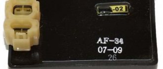
The semiconductor regulator maintains the DC voltage at the output of the synchronous generator, i.e. at the “+V” terminal of the rectifier, at a constant value of 14 V with a tolerance of +0.3 V - 0.6 V.
Rice. 5. Semiconductor regulator with designation of connected terminals
Its work is to change the value of the average value of the excitation current passing through the generator rotor, in instantaneous, precise dependence on changes in the output voltage of the synchronous generator. This voltage is supplied from the “+B” terminal of the rectifier through the ignition switch to the input of the regulator, i.e. to the “+D” terminal, located in a four-pole terminal block with flat plugs, similar to the rectifier. The output terminal of the regulator “DF” is directly connected to the “DF” terminal on the brush holder of the synchronous generator, the “minus” end of the field winding is grounded, so that the generator excitation operates with the so-called. positive regulation. The “+B” terminal of the regulator must be perfectly connected to the “minus” pole of the synchronous generator, battery and frame (ground) of the motorcycle. For safe operation and shielding of the regulator, the regulator casing is also shorted to ground. The remaining terminal of the regulator “54” in the case of our synchronous generator is not connected; it is intended to signal the recharging of a self-excited synchronous generator, i.e. with a nine-diode circuit (usually used on SKODA passenger cars). To ensure constant regulated voltage at different temperatures, the regulator is equipped with compensation circuits, as well as protective elements to increase operational reliability.
The recharge warning lamp relay is a conventional mechanical relay with NC. contacts - its connection to the terminals is visible in the figure.
Rice. 7. Appearance of the electromagnetic relay of the recharge warning lamp
Rice. 8. Diagram of the electromagnetic relay for the recharge warning lamp
Attraction of the armature (opening of contacts) occurs when the DC voltage on the control winding (terminal “86”) is within the range of 4.8 - 8.6 V; this voltage value, taken from the center of the stator winding of the synchronous generator, corresponds to the correct function of all three phases. In the event of a malfunction or complete failure in the operation of one phase, a change in this voltage occurs, which will immediately be manifested by a constant or intermittent light of the warning lamp. Whenever manipulating the relay, it is necessary to ensure that the plastic relay cap is properly seated so that the relay contacts do not become dirty during operation of the motorcycle.