How to assemble a gearbox on a motorcycle in Minsk
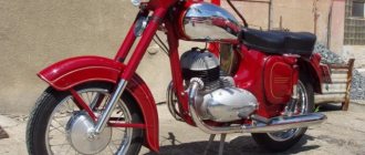
Lightweight 125 cc cars of the Minsk Motorcycle Plant (MMVZ) have long and firmly won the sympathy of motorcyclists. They do the first kilometers, mastering the ABCs of driving. Many remain faithful to this brand for many years due to its unpretentious operation and maintenance, sufficient cross-country ability, and, of course, low price.
Gears do not turn on or off . The reason may be that the gear shift pawl is stuck due to heavy oil contamination or the base of the mechanism is loosened. In such cases, the oil is replaced with clean oil, having first washed the gearbox crankcase with kerosene. The base of the gear shift mechanism is securely fixed.
The gears switch on indistinctly - sometimes only after the second or third attempt, sometimes they switch off on their own, and sometimes they turn off with difficulty. The cause of the malfunction, as in the first case, may be a weakening of the base, but excessive axial movement of the shift shaft cannot be ruled out. To eliminate it, you should loosen the lock nut, tighten the adjusting screw on the gearbox cover until it stops, and then unscrew it a quarter turn and tighten the lock nut again.
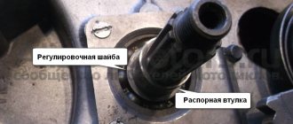
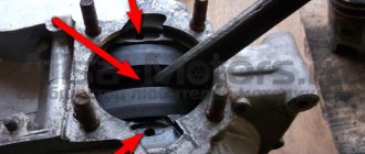
Self-switching off 3rd gear . The most likely cause is axial play of the intermediate shaft. To eliminate the backlash, remove the oil seal housing installed at the output end of the secondary shaft and place the opened intermediate shaft bearing inside the box. Install washers of the same size as the bearing into the resulting recess. Their thickness should be such that they are flush with the plane of the gearbox cover or do not reach it by 0.1-0.2 mm. The washers should not be allowed to protrude outward - then the shaft will be tightened, the bearings and gears will overheat and fail.
If the axial play of the shaft is normal, this means that the transmission may turn off due to a malfunction of the switching mechanism or damage to the working surface of the cams on the gears.
Gear cam repair : 1 - emery wheel; 2 - gear cam.
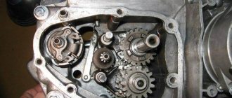
Chipped gear cams can be corrected using an emery wheel, as shown in Fig. 1. In this case, it is necessary to remove the same layer of metal from all three cams, ensuring their simultaneous contact with the cams that work in tandem with them. Note, however, that gears repaired in this way are short-lived, since a hard hardened layer of metal 0.3–0.4 mm thick is removed from the cams, and soon (after 6–10 thousand kilometers) the repair will have to be repeated or the gears replaced.
content .. 11 12 18 ..GEARBOX OF MOTORCYCLE “MINSK” MMVZ 3.111
The motorcycle uses a four-speed gearbox. The gearbox requires careful and careful handling. To avoid disruption of the gearbox, sudden gear shifting and high force on the gear shift pedal are not allowed.
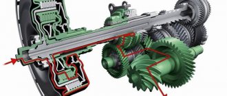
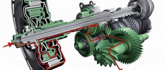
The gearbox diagram is shown in Fig. 14. Gears marked with an X sit rigidly on the shafts, the rest rotate freely on them. In this case, gears 12 and 22 connected to the shift forks are movable, that is, they can move on splines in the axial direction in one direction or another, engaging with the cams of adjacent gears.
Rice. 14. Transmission operation diagram: I - first gear; N - neutral position; II - second gear; .III - third gear; IV - fourth gear; O—neutral position of the moving gear; "—"-. direction of movement of the movable gear when switching; X - gears rotating in concert with the shafts; 1 - fork axis; 2 — fork for shifting 1st and 3rd gears; 3 — gear 1 of the intermediate shaft Z-29; 4 - intermediate shaft; 5 — intermediate shaft bearings; 6 — clutch release rod; 7 - input shaft; 8 — input shaft bearing; 9 — input shaft gear Z-13; 10 — input shaft gear Z-16; 11 — retaining ring; 12 — movable input shaft gear Z-20; 13 — fork for shifting II and IV gears; 14-gear secondary shaft Z-23 (secondary shaft); 15 .- secondary shaft bearing; 16 — drive gear of the main gear; 17 — gear nut; 18 — spacer sleeve; 19 — intermediate shaft gear Z-19; 20 — retaining rings; 21 — intermediate shaft gear Z-22; 22 — intermediate shaft gear Z-26 is movable.
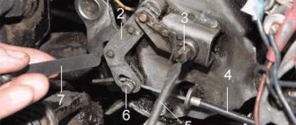
Rice. 15. Gear shift mechanism: 1 — fork axis; 2 — fork for shifting 1st and 3rd gears; 3 - intermediate shaft; 4 — clutch release rod; 5 - input shaft; 6 — movable input shaft gear; 7 — fork for shifting II and IV gears; 8 — clamp; 9 - crankcase; 10 — gear shift pedal; 11 — pedal fastening bolt; 12 — crankcase boss; 13 - base; 14 — return spring; 15 — spring cap; 16 — pawl body; 17 - lower pawl; 18 — upper pawl; 19 — gear shift disc.
In Fig. 14 shows the neutral position, when torque is not transmitted to the secondary shaft and, therefore, to the wheel.
To engage the first gear, the gear shift pedal 10 (Fig. 15) moves down, the pawl 18, resting against the protrusion of the disk 19, turns it to a certain angle. In this case, fork 2, the protrusion of which is placed in the shaped groove of disk 19, moves along axis 1, moving gear 22 (Fig. 14) to the left, the cams of which enter the windows of gear 3. At the same time, fork 13 and movable gear 12 remain in place . Torque is transmitted according to the 14-I scheme.
To engage 2nd gear, the pedal moves up, the lower pawl 17 (Fig. 15) rests on the protrusion of the disk 19 and turns it. In this case, fork 2 (Fig. 14) disengages movable gear 22 from engagement with gear 3, and fork 13 moves movable gear 12 to the left, bringing it into engagement with gear 10. In this case, torque is transmitted according to scheme 14-II.
When the third gear is engaged (the pedal moves up), fork 13 disengages the movable gear 12 from engagement with gear 10, and fork 2 moves the moving gear 22 to the right, bringing it into engagement with gear 21. The torque is transmitted according to scheme 14-III.
When IV gear is engaged (the pedal moves up), the movable gear 22 disengages from the gear 21, and the movable gear 12 engages with the gear 14. In this case, the torque is transmitted according to the 14-IV scheme.
To return the pedal to its original position after each switch, a return spring 14 is used (Fig. 15). To prevent self-switching or self-switching of gears, a ball retainer 8 is used, which holds the gear shift disc in a certain position.
In order to adjust the position of the pawl housing, there is an adjusting screw with a lock nut in the gearbox cover. The screw must be tightened until it stops and loosened 1/4 - 1/2 turn, then locked.
content .. 11 12 18 ..
How to set the outline for the best ignition
Initially, the outline is installed at the factory, when the finished motorcycle is in a state of assembly, and is tightly adjusted with special screws. In most cases, this avoids problems, but sometimes they become loose, disrupting the course of the ignition spark and reducing its intensity.
Setting an outline on a Minsk motorcycle is not easy. This procedure takes a lot of time and effort, and also requires utmost attention from even the most experienced drivers. Therefore, you need to start it only if you are absolutely sure that the problem lies in the outline. You can check this by measuring the intensity of the spark when adjusting the contacts. Changing it indicates a problem, but if it remains stable, no adjustment is required.
Loosen the outline screws and check how the spark changes. If it increases with increasing distance between the contacts, then the plate should be gradually rotated clockwise, and vice versa if it decreases. The steps must be repeated until you get a strong ignition spark that will remain stable when the distance between the contacts changes.
Installing a Minsk motorcycle ignition will be much easier with the assistance of experienced drivers or mechanics if you are new to this matter. However, you can easily do it yourself, paying maximum attention and effort to it, saving a lot on the price of repairing a motorcycle at a service center.
Adjusting the gap in the breaker
Adjusting the gap between the contacts is a simple procedure with which you should begin diagnosing problems. First of all, prepare a key for 10 - you will need it more than once when setting up the ignition in Minsk.
To adjust the gap you will need to do the following:
- rotate the rotor as much as possible, placing it in a position in which the gap will be as wide as possible;
- then it is necessary to loosen the fastening screw, which ensures the connection of the contact post with the cover;
- Having access to the eccentric, begin to tighten it until the gap is about 0.4 mm. You can measure this distance using a special probe - if adjusted correctly, it will be slightly clamped by the contacts.
Next comes setting the ignition timing. It must be performed only after the above steps.
You can set the ignition timing as follows:
- first you need to set the piston to top dead center and turn it 3 millimeters in the opposite direction;
- then pay attention to the starter bolts - lower them and start turning it so that an open circuit is formed between the contacts. You can determine this moment using an ordinary piece of paper - at the moment of rupture it will pass between the contacts without any problems
- Having determined the gap, tighten the bolts and tighten them tightly, then check the breaker and its clearance.
If after this the problem with the ignition on the Minsk motorcycle has not been corrected, then you need to proceed to the next, not the easiest step - installing the outline.
Buy spare parts for the Minsk motorcycle at the best prices
Our regular customers know that on the MotoImport website you can profitably buy a clutch, a generator, or a new clutch for any wheeled vehicle. Spare parts for the Minsk 125 motorcycle are always in stock and available at reasonable prices. The products will allow you to breathe a second life into the vehicle, ensure comfort and safety of its operation in any conditions. We sell parts and components of both domestic and foreign production. You can easily choose an option that suits you in terms of cost and quality of production. Store employees are always ready to provide free advice on the assortment.
Minsk motorcycle front fork: repair or replacement
Before you begin repairing or installing a new front fork on Minsk equipment, you will need to remove it correctly. To do this you need to do the following:
- Remove the wheel and front fender of the motorcycle.
- Unscrew the nut that secures the feather and pull out the spring. At this point you may need to remove the steering wheel.
- Release the lower axle pinch bolt by grasping the sliding tube. After this, you can remove the feather from the bridges.
- If you are unable to release the nib, you will need to lightly tighten the nut holding it in place and then lightly hit it with a block of wood. If necessary, you can remove the headlight along with the cover, gasket and cap.
- Remove the oil seal, then unscrew the rod axis and drain the oil.
After this, you can begin repairing the motorcycle fork or installing a new one. Reassemble the fork in reverse order. Note! All bolts need to be fully tightened only after tightening the nuts that secure the feather.
Clutch, ignition, generator and other spare parts for Minsk 125
Our range of spare parts for Minsk includes parts for 125 and other motorcycle models. You can buy the following products from us at affordable prices:
- ignition;
- generator;
- clutch;
- engine;
- carburetor;
- brake system elements;
- fasteners and much more.
We supply products from trusted manufacturers, and we guarantee that the new fork, gearbox or any other part will fit perfectly and last a long time. Spare parts are intended for Minsk 125 and do not cause problems with replacement. You can install the ignition, clutch or generator yourself if you know the structure of the vehicle and have a tool at hand. We recommend that you consult with store managers about the operating features of the parts and components presented on the website before purchasing them.
Please note that the catalog contains both individual spare parts and entire assemblies. The second option makes it possible to completely replace the faulty unit with a new one and not worry about its stability in operation. We sell both original spare parts for Minsk and analogues with decent performance characteristics.
