Russian motorcyclesIZH motorcycles
Among domestic middle-class motorcycles, the leader was the IZH Jupiter series.
A special feature of these motorcycles was a two-cylinder engine, which provided some advantage over another Izhevsk machine-building motorcycle.
Serial production of IZH Jupiter began in 1961; this series included five generations and was produced until 2008.
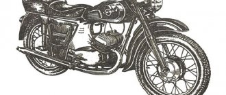
Now let’s look at the third generation model “IZH Jupiter 3”.
It was no coincidence that this model was chosen, since at one time completely redesigned engines began to be installed on these motorcycles, which had significantly increased power compared to their predecessors , so IZH Jupiter 3 was already the first model of a new generation of motorcycles.
It should also be noted that this motorcycle was produced for a very long time - 10 years (from 1971 to 1981) and in this indicator only IZH-Jupiter 5 surpasses it.
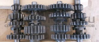
Motorcycle IZH Jupiter disassembly and assembly of gearbox
Disassembly and assembly of the gearbox and shift mechanism of the IZH-U motorcycle are carried out as follows.
Disassembly. Remove the engine from the frame and disconnect the carburetor pipe. Remove the shift pedals and kick starter, drain the oil from the gearbox crankcase by unscrewing the plug. Unscrew the mounting screws and carefully remove the left crankcase cover without damaging the paper gasket, and also remove the right cover. Disassemble and remove the clutch mechanism. Remove the hatch cover located at the bottom of the crankcase and loosen the flywheel pinch bolt. Remove the lower pipe of the rubber boot and, by unscrewing the seven screws and the flywheel tightening bolt, separate the crankcase into two halves. All gearbox parts, except the output shaft, can be removed from the crankcase. To disassemble the shift mechanism, you need to remove the clutch release cam and remove the key. When disassembling, it is necessary to monitor the order in which the parts were assembled. Pay special attention to the adjusting washers. Assembly. The gearbox and shift mechanism are assembled in the right half of the crankcase. Install the shift mechanism shaft along with its parts and key. Place the clutch release cam and secure it. Install the intermediate shaft into the ball bearing without the first gear and the input shaft, putting a 2 mm thick ring on it. Install the worm shaft and shift forks, connecting them to the carriage gears of the primary and secondary shafts, and put a 1.4 mm thick adjusting washer on the right end. The worm shaft is installed so that the existing core marks on the sector teeth and the worm shaft coincide. This is important for proper gear engagement.
Place a key on the crankshaft axle shaft of the right half of the crankcase and put on the flywheel. Clean the crankcase connector surfaces from varnish and re-coat them with bakelite varnish. Insert the key into the left crankshaft axle shaft. Place an adjusting washer 0.2-0.3 mm thick on the left end of the worm shaft. Inserting the first gear gear into the left half of the crankcase and supporting it with the fingers of your left hand, through the hole in the crankcase wall, begin connecting the left half of the crankcase with the right, for which you put the left half of the crankcase on the gear shift shaft and, turning the flywheel, align the crankshaft key with the flywheel keyway and connect the crankcase halves. At the moment of connecting the crankcase, after the first gear gear is put on the intermediate shaft, use a screwdriver to remove the gear shift lock through the hole in the crankcase, which will allow the worm shaft to fit into place. Once the crankcase is connected, secure the mounting screws. Set equal gaps between the flywheel and the crankcase walls, and then tighten the flywheel pinch bolt until it stops.
Source
"Sores"
There are three problems in the planetary checkpoint:
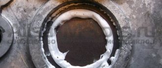
I solve the problem with oil leakage very easily and simply: I take out the retaining ring; I remove the intermediate shaft bearing, degrease the plug, retaining ring, mounting hole, then apply sealant to the outer edge of the plug, put it in place and immediately press it with the bearing and voila - the leak is eliminated!
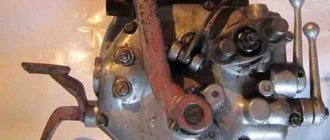
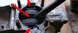
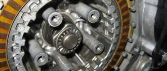
Due to a factory defect, the gear-carriage for engaging the first-third gear does not fully engage the first-gear gear with its cams, but only in a small part, barely catching the gear with its cams, which is why the edges quickly wear out and the first gear begins to knock out.
This moment is clearly visible in the photo. For this particular gear, the hook was no more than a couple of millimeters. It is difficult to cure this “sore”: from the side of the first gear gear, you need to grind the end of the intermediate shaft by 3-4 mm and, using adjusting washers, move the first gear gear to the carriage. I don't see any other way.
During operation, the bolts securing the stop are constantly unscrewed, either due to vibration or something else - they are unscrewed and that’s it, no matter how you tighten them... Even special lock washers do not help. I struggled with this disgrace for a long time using all the traditional methods known to me and came to the conclusion that the best solution to this problem is red thread locker. Feel free to put bolts on it and get rid of this problem once and for all.
How to properly assemble a Jupiter 5 gearbox
The engine of the Izh Jupiter 5 motorcycle must be removed from the frame when disassembling and assembling the gearbox. In this case, you do not have to disassemble the cylinder-piston group, but be sure to disconnect the inlet pipe from the cylinders. Drain the oil from the crankcase before disassembling.
Disassembly. Remove the trigger and shift levers, left crankcase cover and gasket. Disassemble the clutch, transmission from the engine to the clutch and the trigger mechanism. Disconnect the lower pipe of the motorcycle wheel drive chain cover from the engine crankcase. Knock out the mounting sleeve at the front of the engine to half its length.
Unscrew the seven screws securing the crankcase halves and, having unscrewed the nuts, remove the engine mounting bolt at the rear. Remove the remote flywheel cavity hatch cover with the gasket and drain the oil. Use the special wrench from the tool kit to loosen the bolt holding the flywheel together. Separate the crankcase halves using screwdrivers, installing them in the grooves of the rear and front parts of the crankcase, or using a hammer and drift. Remove the remote flywheel and keys.
Remove the input and intermediate shafts with gears and washers, the worm shaft with gear shift forks from their seats, and mark the installation locations and the number of adjusting washers. Disassemble the gear shift mechanism in the following order: * straighten the ends of the cotter pin and remove it from the hole in the gear shift mechanism shaft; * unscrew the coupling bolt on the cam, remove the adjusting washers and the clutch cam, remove the key from the groove; * remove the gear shift shaft, anchor stopper and sector, taking precautions, since the mechanism spring with its ends is wound behind the anchor stop; * straighten the lock washer and unscrew the nut securing the anchor stop to the crankcase; Disconnect the spring from engagement with the bolt stop and remove the stopper.
Disassemble the secondary shaft in the following sequence:
* remove the rubber cap from the clutch pusher; * straighten the lock washer of the secondary shaft sprocket; * unscrew the nut (left-hand thread) and, holding the shaft, remove the washer and sprocket; * remove the shaft, making sure that the rollers do not fall apart; * press out the oil seal, remove the installation and support rings from the hole in the crankcase half; * press out the outer ring of the roller bearing.
* place a 1.35 mm thick support washer on the end of the hole in the right half of the crankcase and insert the worm shaft with the locking grooves facing up; * using a ruler and a caliper depth gauge, measure the height of the protrusion of the shaft support plane above the crankcase connector plane; * measure on the left half of the crankcase the distance between the reference plane of the shaft seat and the plane of the connector. The difference in these dimensions gives the axial clearance of the worm shaft, which should be 0.1. 0.4 mm; * if the gap is more than 0.4 mm, then select the required number of washers with a thickness of 0.2. 0.3 mm, which during assembly, install on the end of the shaft from the side of the grooves for the retainer; * remove the worm shaft and support washer.
How to rebuild a gearbox on Jupiter 5
The engine of the Izh Jupiter 5 motorcycle must be removed from the frame when disassembling and assembling the gearbox. In this case, you do not have to disassemble the cylinder-piston group, but be sure to disconnect the inlet pipe from the cylinders. Drain the oil from the crankcase before disassembling.
Disassembly. Remove the trigger and shift levers, left crankcase cover and gasket. Disassemble the clutch, transmission from the engine to the clutch and the trigger mechanism. Disconnect the lower pipe of the motorcycle wheel drive chain cover from the engine crankcase. Knock out the mounting sleeve at the front of the engine to half its length.
Unscrew the seven screws securing the crankcase halves and, having unscrewed the nuts, remove the engine mounting bolt at the rear. Remove the remote flywheel cavity hatch cover with the gasket and drain the oil. Use the special wrench from the tool kit to loosen the bolt holding the flywheel together. Separate the crankcase halves using screwdrivers, installing them in the grooves of the rear and front parts of the crankcase, or using a hammer and drift. Remove the remote flywheel and keys.
Remove the input and intermediate shafts with gears and washers, the worm shaft with gear shift forks from their seats, and mark the installation locations and the number of adjusting washers. Disassemble the gear shift mechanism in the following order: * straighten the ends of the cotter pin and remove it from the hole in the gear shift mechanism shaft; * unscrew the coupling bolt on the cam, remove the adjusting washers and the clutch cam, remove the key from the groove; * remove the gear shift shaft, anchor stopper and sector, taking precautions, since the mechanism spring with its ends is wound behind the anchor stop; * straighten the lock washer and unscrew the nut securing the anchor stop to the crankcase; Disconnect the spring from engagement with the bolt stop and remove the stopper.
Disassemble the secondary shaft in the following sequence:
* remove the rubber cap from the clutch pusher; * straighten the lock washer of the secondary shaft sprocket; * unscrew the nut (left-hand thread) and, holding the shaft, remove the washer and sprocket; * remove the shaft, making sure that the rollers do not fall apart; * press out the oil seal, remove the installation and support rings from the hole in the crankcase half; * press out the outer ring of the roller bearing.
* place a 1.35 mm thick support washer on the end of the hole in the right half of the crankcase and insert the worm shaft with the locking grooves facing up; * using a ruler and a caliper depth gauge, measure the height of the protrusion of the shaft support plane above the crankcase connector plane; * measure on the left half of the crankcase the distance between the reference plane of the shaft seat and the plane of the connector. The difference in these dimensions gives the axial clearance of the worm shaft, which should be 0.1. 0.4 mm; * if the gap is more than 0.4 mm, then select the required number of washers with a thickness of 0.2. 0.3 mm, which during assembly, install on the end of the shaft from the side of the grooves for the retainer; * remove the worm shaft and support washer.
Assembly. Assemble the secondary shaft and install it in the right half of the crankcase in the following order:
* install the support and retaining rings into the hole in the right half of the crankcase; * press in the outer ring of the roller bearing and the oil seal until it stops; * tap the crankcase along the bearing ring at three or four points;
How to properly assemble a gearbox for Izh Jupiter 5
The assembly of the Izh-Planet 5 box is often carried out during its repair or replacement of parts. This unit is not highly reliable. This is due to the low quality of components, poor assembly, and poor requirements for the manufacturing accuracy of bearings, crankcases and other mechanisms. You can find your advantages too. Firstly, it is cheap to produce. Secondly, it can be repaired with your own hands. Let's look at what the part is and how to assemble the Izh-Planet 5 box, and also learn useful recommendations.
Most common problems
In some cases, the simplest method will help, without completely disassembling and then reassembling the Izh-Planet 5 box. It is necessary to place the motorcycle on the right side, and then remove the kick starter and gear shift foot along with the shaft. Next, the crankcase cover and clutch basket along with the discs are dismantled.
When the gears of the box wear out, the meshing of the teeth deteriorates. In turn, this leads to slipping, jerking and failure of the second gear. Another reason could be wear on the input shaft bearings. Since it moves slightly to the left due to vibration, it is necessary to move it into place with light blows using a mallet. The installation of washers of suitable diameter will allow you to fix the element in the desired position. Then the bearing stopper and other dismantled parts are reassembled in the reverse order.
Description of design
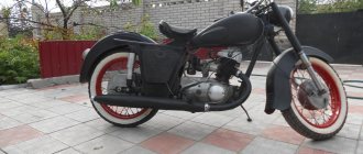
So, this motorcycle was first shown in 1971.
It was produced in two versions - “IZH Jupiter 3” and “IZH Jupiter 3K”.
They differed in that the “3K” was additionally equipped with a sidecar , but it had the ability to be detached from the motorcycle.
At that time, Jupiter 3 had a modern appearance and was well made, although it was based on its predecessor. All elements of the motorcycle were attached to a tubular frame.
To increase comfort, the front suspension travel was increased and the rear shock absorbers were made softer.
They changed the shape of the tank, it stopped being teardrop-shaped. But the headlight did not change; its housing continued to house the speedometer, ignition switch and warning lamps.
The seat is undivided, double . A rear fender with a brake light, turn signals and a license plate placed on it was attached to the seat body from below.
Turn signals on the IZH Jupiter family began to be installed precisely from the third model.
under the seat on both sides of the motorcycle , the left one was intended for installing the battery, and the right one was for storing keys.
The engine was located under the tank, which ensured that fuel flowed into the carburetor by gravity. To prevent spontaneous leakage of gasoline, a tap was placed on the tank.
The cylinders had an in-line arrangement. When designing a new engine for this motorcycle, the position of the cylinder fins was revised, which subsequently ensured better cooling .
One elbow came out of each of the cylinders, to which two exhaust pipes were screwed, mounted on the sides of the motorcycle under the footpegs.
The power system consisted of a single carburetor located behind the cylinders and connected to them by a pipe with a double outlet. In the base, the motorcycle came with protective covers covering the carburetor.
By reworking the engine, the designers managed to increase its power by 6 hp, which affected the speed; it increased to 120 km/h.
The gearbox was made integral with the engine. Torque was transmitted via a multi-plate clutch. The drive to the rear wheel was carried out by a chain.
The rear drive sprocket was housed in an aluminum housing.
The front suspension was made in the form of a telescopic fork, and the rear suspension was pendulum with two shock absorbers .
The brakes on both wheels are mechanically driven drums.
At one time , this motorcycle was awarded the State Quality Mark because it was reliable, easy to repair, and easy to start, compared to the IZH Planet.
Its only . It practically consisted of two contact systems, one for each cylinder.
This affected the convenience of installing the ignition; it was difficult to achieve the same advance angle on the cylinders.
The Kawasaki Versys 650 will be an excellent companion on long trips; you will find its technical characteristics in our review.
The bike that received the status of a “legendary” motorcycle:
Common faults
The simplest method that will help in some cases. Place the motorcycle on its right side, then remove the kick starter and gear shift lever along with the shaft. Then remove the left crankcase cover, and then remove the clutch basket along with the discs. During operation, the gearbox gears wear out, which causes the meshing of the teeth to deteriorate. This leads to slipping and jerking of the transmission until the second gear fails. Sometimes, when replacing a gear, the problem is not always solved, and lies in the wear of the bearings of the input shaft, which moves to the left over time due to vibrations. To fix the problem, you need to remove the stopper of the input shaft bearing, then move this bearing with light blows of a mallet or with a hammer through the “spacer”, so as to move the shaft to the right. To fix it in this position, you should place washers of appropriate diameter under the bearing. Using the number and thickness of washers, ensure that there is no play in the input shaft, then return the bearing stopper to its place, reassemble the clutch basket and other parts in the reverse order.
We would like to warn you right away: you should mark and write down the previous location of the adjusting washers when dismantling the switching mechanism.
Other faults
It happens that disassembling/assembling the Izh-Planet 5 box may be necessary if the fourth speed disappears. This is often due to broken bearings on the output shaft. Such a nuisance occurs due to the presence of axial play, displacement of the bearing assembly, or its failure. You can try to fix the problem in the same way as repairing the second gear. If this does not help, you will need to completely disassemble the unit.
When the speed switch jams from a high range to a low mode, the spring system of the switching mechanism has failed. It needs to be replaced. Strained operation of the unit after assembling the Izh-Planet 5 gearbox indicates incorrect installation of the adjusting washers. To avoid this, it is necessary to mark and record the previous placement of these elements during the process.
Large selection of spare parts for IZH motorcycles
In this section we have collected a wide range of spare parts for the IZH Planet motorcycle. The proposed list of parts will be indispensable for those who want to return to operation an inherited unit, or plan to buy a used retro motorcycle for further restoration. These components have the following advantages:
Since the “Planet” has a simple and reliable design, most motorcyclists repair the “iron horse” themselves. Fortunately, this motorcycle responds to care. Despite its age, the IZH “Planet” remains a fully functional vehicle.
Disassembling and assembling the Izh-Planet 5 box
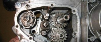
First, you will need to completely dismantle the clutch, starting device and motor transmission, and also drain the oil. After these manipulations have been carried out, you can begin to remove the gearbox. In the area of the right side of the motor, unscrew the eight mounting screws. The driver's footrests, foot brake lever, and crankcase cover on the right side are removed. The clutch cable is disconnected and the ball and pusher of the input shaft are removed. After this, the circuit is disconnected. Designations in the photo below: clutch discs (1,3), lower disc (2), inner drum (4), nuts (5, 6).
Main stage
As noted in the assembly diagram of the Izh-Planet 5 box, further disassembly operations are carried out above the insides of the roof of the unit, since the secondary shaft and sector could remain in it. If it is necessary to remove them, you need to straighten the petals of the lock washer, unscrew the nut, remove the star and washer. Holding the gear very carefully to prevent the shaft from jumping out, the cover is moved to a clean and flat surface with the gear facing up.
It is worth noting that the bearing of this part of the assembly does not have a retaining ring. Therefore, when removing the shaft with bearing, the rollers may fall out, so be careful. If the specified element has exhausted a decent service life, there is a risk that when dismantling the secondary shaft, the outer ring may jump out of the seat and remain on the rollers. Next you need to start pressing out the oil seal. To do this, the installation rings are removed from the hole in the cover, after which the outer ring of the bearing is removed.
Instructions for assembling the gearbox for IZH Jupiter 5 | Topic author: Deidre
Hello, please post instructions on how to properly assemble the gearbox on an IZH Jupiter 5. I bought a Yupak secondhand, it was completely disassembled! I’m looking at the box of all sorts of washers and bolts for gears and I don’t know what to put where, tell a newbie how what and where should be in the gearbox, it would be nice to have a “video” or at least “draw a picture” =) please give me an idea))
Alexander (Kumaree) there are detailed instructions in the Jupiter book.
I changed everything based on it
Maxim (Kalen) Can you take a photo of this book for me where you read the assembly instructions?
Alexander (Kumaree) there is this. there you can search https://www.motoizh.ru/. but I can’t take a picture. the camera is covered
Alexander (Kumaree) https://www.moto4you.ru/content/view/68/29 Here’s something else I found. There are instructions text + pictures but this is disassembly. just do the opposite)))
Maxim (Kalen) Thank you very much =)
Alexander (Kumaree) yes you're welcome
Evgeny (Trevon) Alexander,
Vladimir (Nakapati) How should the forks be positioned on Jupiter 5... Why, when you engage first gear, it sinks and does not turn anything at all, shafts or gears.
Tags: How to properly assemble a gearbox for Izh Jupiter 5
Final stage
Next, the second and third speed gears are removed from the input shaft, after which the input shaft is dismantled. To do this, you will need to carefully knock it out using a stopper and a light hammer. The upper and lower forks are removed.
Next comes the intermediate shaft assembly. Using a screwdriver or other suitable tool, bend the clamp with the neutral indicator and carefully pull out the worm wheel. On its far side there are shims that could stick to the crankcase. They need to be collected and stored with the rest of the removed parts. Next is the turn of the copy shaft. Check the edges of the shaped sockets in which the guide forks move. They should not have chips or dents. We unscrew a couple of screws securing the switching mechanism, which is also removed. Now you can replace unusable parts and assemble the Izh-Planet 5 gearbox according to the scheme. The figure below shows: retaining cap (1), bolt (2), crankshaft sprocket (3), double-row chain (4), clutch drum (5), input shaft (6).
Completion
Above is the assembly of the Izh-Planet 5 box in detail. After tightening the clamps, you need to check the drive sprocket again for correct rotation. At the end, a ratchet with a spring, a clutch drum bushing and itself are installed, and the chain drive is connected to the drive sprocket, and transmission oil is poured into the box.
The Izh Planet 5 gearbox is four-speed, three-shaft with constant mesh spur gears and foot-operated gear shifting. Switching is carried out using a copy shaft, which is located inside the box; the shift fork pins fit into its grooves. The copy shaft rotates from the shift selector, which in turn is connected to the foot lever. The secondary shaft is hollow and fits onto the end of the primary shaft. The main gear sprocket is located on the secondary shaft. The gearbox is located in the same crankcase with the motorcycle engine, together forming a single power unit. The gearbox is lubricated by oil poured into the engine crankcase. The IZH Planet 5 gearbox can be disassembled without removing the engine, however, for complete disassembly and greater convenience, you can remove the engine from the motorcycle frame. Today we will look at disassembling the Izh Planet 5 gearbox step by step.
Drain the oil from the motorcycle crankcase by placing it on a stand. Then, after unscrewing the bolts, remove the right engine cover as well as the gear shift levers and kickstarter. Having disconnected the chain casing from the box, we separate the chain links. We take out the clutch rod, and then use a large screwdriver or chisel to bend the sprocket retaining washer. Now you need to unscrew the sprocket nut; to do this, wedge the sprocket between its teeth and the engine crankcase with a suitable metal object, preventing its rotation. The thread on the nut is left-handed, so you need to unscrew it clockwise using a 36mm wrench. Use a screwdriver to unscrew the seven screws of the box cover, remembering the length of the screws (it is not the same) and do not lose the aluminum sealing washers under the heads of the two lower screws.
Using a universal puller, remove the secondary shaft sprocket. Through the gap formed between the cover and the crankcase, we hold the gear sector of the starting device. If this is not done, the sector moves behind the cover and it, warping when the puller is tightened, may crack. Do not “help” the puller by wedging the gap with a screwdriver or similar tool. This will damage the cover gasket and, most importantly, cause dents to form at the junction of the cover and the crankcase, which will lead to oil leakage.
Remove the gear selector from the axle.
Remove the shift shaft along with the ratchet mechanism.
Lifting the follower shaft, remove the pin of the shift fork for 2nd and 4th gears from its groove. Remove the fork from the rod, and from the primary gear the 2nd and 4th gears and the washer.
Motorcycle IZH-Jupiter technical characteristics
Home > IZ Reviews
Motorcycle IZH-Jupiter technical characteristics general data
Motorcycle type - single Base, mm - 1360 Ground clearance, mm -135 Dimensions, mm: Length - 2115 Width - 780 Height - 1025 Saddle height - 780 Motorcycle dry weight, kg -160 Maximum speed, km/h - 110 Fuel tank capacity , l — 15 Fuel consumption rate on the highway, l/100 km — 4 Fuel range, km — 375 Filling oil capacity, l: gearbox housing — 1 each front fork leg — 0.15 rear suspension elements (two) — 0 .12 air purifiers - 0.2
Motorcycle IZH-Jupiter technical characteristics engine
Engine type - two-stroke with two-channel return purge Number and arrangement of cylinders - two, vertical in-line Cylinder diameter, mm - 61.75 Piston stroke, mm - 58 Displacement, cm cubed - 347 Compression ratio - 6.7 - 7.0 Maximum power, l. With. — 18 Number of revolutions at maximum power, rpm — 4700-5100 Tax power, n. pp. - 1.33 Cylinder head: material - aluminum alloy combustion chamber shape - hemispherical Gasket material - rayasbestos Piston: material - aluminum alloy shape - convex Number of piston rings - 3 Piston pin (type) - floating Piston pin diameter, mm - 14 Protection against axial displacement - with stoppers. Valve timing, in degrees of crankshaft rotation: beginning of intake to c. m.t. - 75° end of intake after c. m.t. - 75° start of release to c. m.t. - 80° end of release after n. m.t. - 80° start of blowing after n. m.t. - 58° end of blowing after n. m.t. - 58° Engine lubrication - oil with gasoline Carburetor - K-28Zh Air cleaner - contact-oil Fuel filter - mesh in the sump
Motorcycle IZH-Jupiter technical characteristics power transmission
Clutch - multi-plate in an oil bath Gearbox: type - four-speed control - foot gear ratios: in first gear -3.17 in second gear - 1.71 in third gear - 1.26 in fourth gear - 1 Total gear ratio (from the engine to the rear wheel): in first gear - 18.98 in second gear - 10.24 in third gear - 7.54 in fourth gear - 5.89 Forward gear: type - roller chain gear ratio - 2.57 Rear gear: type — roller chain gear ratio — 2.63 Chassis Frame — tubular, non-separable welded Front fork — telescopic with hydraulic shock absorbers Rear suspension — lever spring with hydraulic shock absorbers Tires: type — straight-bezel size in inches — 3.25-19 Brakes — shoe brake drive — mechanical separate
Motorcycle IZH-Jupiter technical characteristics ignition, electrical equipment
Ignition system - battery Battery battery: brand - 3-MT-7 capacity, a-h - 7 voltage, V - 6 Generator: brand - G36M2 voltage, V - 6 power, W - 45 Drive - the generator is mounted on the right axle of the crankshaft engine Regulator relay - two-stage Ground connection terminal - minus Signal - S-37 Headlight - FG-38
Similar articles:
Tuning the IZH Jupiter engine
Before you start, you need to decide how much power you would like to give to your engine. If you are quite satisfied with the average power, then you will need a ZiD-200 resonator. But if you want to make the IZH Jupiter 5 motorcycle fast and powerful, start tuning the engine by installing a resistor from the SMB-5 “motoblock”.
Replacing the air filter plays a big role in engine modification. The better the air is cleaned, the more horses the engine will be able to produce. After all, the degree of engine overheating depends on the amount of incoming air. It is best to use imported air filters. They provide improved cleaning and longer service life.
Next you should work hard on the injection system. An excellent option is to install a “Planet” carburetor with a diffuser diameter of 0.32 cm. Two carburetors will provide much greater acceleration and good dynamics. We take the flanges securing the cylinder from the standard tube, grind out the aluminum studs, and cut off the flange from the carburetor from the inlet tube from the Planet.
We grind the ends of the cylinder heads on a machine, and press the cylinders themselves. The maximum permissible volume of PIC is 18 cubic meters. see Install factory copper layers under the cylinder heads. And we adjust the ignition advance angle to increase compression.
We use the second flange from the old carburetor. Then we weld the parts using “cold” welding. And finally, we modify the assembly to be compatible with the inlet channels. all the cracks with epoxy liquid . Voskhod carburetors will provide uniform traction. In this simple way, you can add not only a couple of additional horses to your pet, but also provide more lively dynamics that give a good riding experience. The motorcycle is very reliable for everyday use, and if you take good care of it, breakdowns will occur very rarely.
Repair
Once the unit has been gutted, you can begin to determine the parts that need to be replaced. As a rule, you have to buy a set of shims, a set of gaskets and sealant. This is the case if there are no more serious damage. Once you have decided on the elements to be replaced, you will need to adjust the worm shaft axis, and after final assembly, the clearance along the axis of the primary, intermediate and secondary shafts.
Adjusting washers are placed on the far ledge of the copy roller; they should be lubricated with a special compound. A support washer is mounted on the near edge, and the shaft is put in place. It should be turned so that the neutral sensor with its protrusion fits into the deepest groove. Then, using a ruler (without the gearbox cover yet) on the plane of the crankcase, measure the gap between the washer and the dipstick. It should be no more than 0.2 mm. Depending on the indicator, regulators are added or removed. If it is impossible to accurately set the gap, it is better to make it smaller.
Assembling the box on the Izh-Planet 5 motorcycle
For proper assembly, you first need to install the input shaft, then the first gear gear with the groove down. Then the return spring is mounted with the range shift shaft; first, put on the spring mechanism and place the block in the seat. After this, a worm shaft with adjusting washers is installed. To make installation easier, lubricate the moving mechanisms with Lithol.
When installing the unit, care must be taken not to damage the neutral speed sensor. To get the shaft into place, use a screwdriver to bend this indicator slightly. When installing, remember the small washer, which eliminates play. A similar part is installed on the copy shaft. After this, the gear shift compartment is installed.
Preparing for assembly
Preparation for assembly can be divided into two main stages: measuring and, if necessary, eliminating the axial play of the tracer shaft and checking the suitability of the secondary shaft bearing for further operation.
The first stage is measuring and eliminating the axial play of the copy shaft
We put adjusting washers on the tracking shaft from the locking side. In my case, there were four adjusting washers, but you may have more or less, or maybe not... We move the locking bar to the side and install the copy shaft in its place. We put a standard thrust washer on the second end of the tracing shaft.
We place a new gasket (required) on the plane of the gearbox cover connector, on which you will later finally assemble the gearbox, and tighten the gearbox cover fastening screws with the required force.
We turn the engine over and measure the axial play of the copy shaft, the norm is 0.2-0.4 mm, but it will be better if you can ensure the axial play at a level of no more than 0.2 mm. Adjustment of axial play is accomplished by simply adding or removing shims.
I measure the play with an indicator. If you don’t have one, try measuring the backlash with a caliper; if you don’t have a caliper, so be it - measure by eye...
Second stage: checking the suitability of the secondary shaft for further use
Under normal operating conditions, the secondary shaft bearing runs for quite a long time. But no matter how much we want and try, it wears out. It would be nothing if it weren’t for safety: if your secondary shaft bearing falls apart while driving, and it will certainly fly apart if you don’t change it in time, the gearbox sticks together with the rear wheel, and it’s tight and you’re grinding the asphalt with your butt...
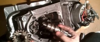
Carefully, take out the secondary shaft over some tray and carefully inspect the shaft bearing raceway, the races and the rollers themselves. The working surfaces of the bearing and rollers should be free of holes, edges, signs of wear or overheating. The path must have a perfectly flat working surface.
Example of a secondary shaft race and race in perfect condition.
To facilitate reassembly, apply some kind of lubricant, such as lithol, to the treadmill and carefully place the rollers on the track and, turning it a little, insert the shaft into the cage. As soon as the sprocket splines rest against the edge of the oil seal, use a thin screwdriver in a circle to straighten the edge of the oil seal and push the shaft until it stops. And immediately, so that the shaft does not fall out, put the sprocket on it and secure it with a nut.
Important
When performing these operations, follow the mark in the middle part of the sector. It should coincide with a similar mark on the shaft. The last step is to install the crankcase cover. If the work is carried out correctly, it will sit in its place without problems.
It is necessary to ensure that all rods and shafts coincide with their original mounting sockets. They should rotate freely without creaking or jamming. Use moderate force when tightening the screws as the threads in a soft metal crankcase can easily be stripped. All fasteners are tightened evenly to avoid distortion.
Source