Assembly of the Izh Planet 5 box
Let's look at what the Izh Planet gearbox is.
We will learn not only how to assemble it, but also how to identify faults and eliminate them. It is not uncommon to experience problems when riding an Izh Planet 5 motorcycle due to the low reliability of the gearbox. This is due to low-quality components, primitive production of the 20th century and low requirements for the precision of manufacturing the crankcase, bearings, gears and shafts. There are, of course, some advantages to the simplicity of the design of such an Izh Planet gearbox; it is low-cost production, which is rather better for the manufacturer. But the main advantage is the ability to repair it yourself. Here we will look at what the Izh Planet gearbox is, we will learn not only how to assemble it, but also how to identify faults and fix them.
To begin with, I would like to announce the list of numbers of bearings and seals used in the IZh gearbox:
How to properly assemble a gearbox for Izh Jupiter 5
The assembly of the Izh-Planet 5 box is often carried out during its repair or replacement of parts. This unit is not highly reliable. This is due to the low quality of components, poor assembly, and poor requirements for the manufacturing accuracy of bearings, crankcases and other mechanisms. You can find your advantages too. Firstly, it is cheap to produce. Secondly, it can be repaired with your own hands. Let's look at what the part is and how to assemble the Izh-Planet 5 box, and also learn useful recommendations.
Common faults
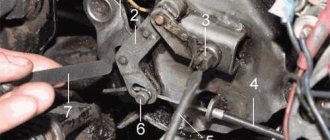
The simplest method that will help in some cases. Place the motorcycle on its right side, then remove the kick starter and gear shift lever along with the shaft. Then remove the left crankcase cover, and then remove the clutch basket along with the discs. During operation, the gearbox gears wear out, which causes the meshing of the teeth to deteriorate. This leads to slipping and jerking of the transmission until the second gear fails. Sometimes, when replacing a gear, the problem is not always solved, and lies in the wear of the bearings of the input shaft, which moves to the left over time due to vibrations. To fix the problem, you need to remove the stopper of the input shaft bearing, then move this bearing with light blows of a mallet or with a hammer through the “spacer”, so as to move the shaft to the right. To fix it in this position, you should place washers of appropriate diameter under the bearing. Using the number and thickness of washers, ensure that there is no play in the input shaft, then return the bearing stopper to its place, reassemble the clutch basket and other parts in the reverse order.
We would like to warn you right away: you should mark and write down the previous location of the adjusting washers when dismantling the switching mechanism.
Assembly procedure for the Izh Planet 5 gearbox
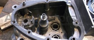
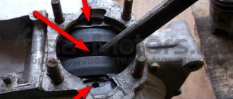
If you are doing a complete overhaul of the engine, and at the same time the gearbox, after the above-mentioned repair work has been completed, and replacement of all worn components after complete disassembly of the gearbox, its correct assembly will be required. The first step is to install the input shaft, then install the first speed gear with the groove down. Next, the return spring is installed with the gear shift shaft, while the spring is first put on, then the assembly is placed in its seat. Then the input shaft yokes and gears are installed. Then we take the worm shaft, first putting on the adjusting washers, usually in the amount of three pieces.
To make it easier to install the worm shaft, lubricate the adjusting washers with lithol, as well as the shaft itself. Due to this, the washers will not fall off during installation. When installing this shaft, be careful not to damage the neutral speed sensor. By slightly bending it with your finger or a screwdriver, the worm shaft will fit completely into place. Now all that remains is to insert the copy shaft.
After installing it, do not forget about such a small but extremely important washer that presses the input shaft to eliminate play. The same washer is placed on the copy shaft.
Then we install the gear shift sector.
Pay attention to the mark in the middle part of the sector, which during installation must be aligned with the mark on the shaft. Well, lastly we put the crankcase cover. If you did everything correctly, then the lid will sit in place without jamming.
It is important that all the rods and shafts coincide with their seats in the cover, and they must rotate freely, without jamming or grinding. When tightening the cover screws, do not use excessive force. The crankcase material is made of a soft material that is easy to strip threads. All bolts must be tightened evenly to avoid misalignment.
After tightening, check again by rotating the drive sprocket, because it is possible that the shaft is pinched. The number of shims will need to be changed. If you did everything correctly, move on. Install the ratchet with the return spring, then the clutch drum bushing and the drum itself, connecting the drive chain to the drive sprocket.
Don't forget to fill the gearbox with gear oil. The level can be determined by the dipstick; the filling volume is 1 liter of oil. It is advisable to use good oil. Then a properly assembled and repaired Izh Planet 5 gearbox will be able to serve for many years, and shifting will be easy and clear.
Source
How to properly assemble a Jupiter 5 gearbox
The engine of the Izh Jupiter 5 motorcycle must be removed from the frame when disassembling and assembling the gearbox. In this case, you do not have to disassemble the cylinder-piston group, but be sure to disconnect the inlet pipe from the cylinders. Drain the oil from the crankcase before disassembling.
Disassembly. Remove the trigger and shift levers, left crankcase cover and gasket. Disassemble the clutch, transmission from the engine to the clutch and the trigger mechanism. Disconnect the lower pipe of the motorcycle wheel drive chain cover from the engine crankcase. Knock out the mounting sleeve at the front of the engine to half its length.
Unscrew the seven screws securing the crankcase halves and, having unscrewed the nuts, remove the engine mounting bolt at the rear. Remove the remote flywheel cavity hatch cover with the gasket and drain the oil. Use the special wrench from the tool kit to loosen the bolt holding the flywheel together. Separate the crankcase halves using screwdrivers, installing them in the grooves of the rear and front parts of the crankcase, or using a hammer and drift. Remove the remote flywheel and keys.
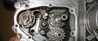
Remove the input and intermediate shafts with gears and washers, the worm shaft with gear shift forks from their seats, and mark the installation locations and the number of adjusting washers. Disassemble the gear shift mechanism in the following order: * straighten the ends of the cotter pin and remove it from the hole in the gear shift mechanism shaft; * unscrew the coupling bolt on the cam, remove the adjusting washers and the clutch cam, remove the key from the groove; * remove the gear shift shaft, anchor stopper and sector, taking precautions, since the mechanism spring with its ends is wound behind the anchor stop; * straighten the lock washer and unscrew the nut securing the anchor stop to the crankcase; Disconnect the spring from engagement with the bolt stop and remove the stopper.
Disassemble the secondary shaft in the following sequence:
* remove the rubber cap from the clutch pusher; * straighten the lock washer of the secondary shaft sprocket; * unscrew the nut (left-hand thread) and, holding the shaft, remove the washer and sprocket; * remove the shaft, making sure that the rollers do not fall apart; * press out the oil seal, remove the installation and support rings from the hole in the crankcase half; * press out the outer ring of the roller bearing.
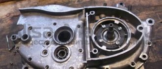
* place a 1.35 mm thick support washer on the end of the hole in the right half of the crankcase and insert the worm shaft with the locking grooves facing up; * using a ruler and a caliper depth gauge, measure the height of the protrusion of the shaft support plane above the crankcase connector plane; * measure on the left half of the crankcase the distance between the reference plane of the shaft seat and the plane of the connector. The difference in these dimensions gives the axial clearance of the worm shaft, which should be 0.1. 0.4 mm; * if the gap is more than 0.4 mm, then select the required number of washers with a thickness of 0.2. 0.3 mm, which during assembly, install on the end of the shaft from the side of the grooves for the retainer; * remove the worm shaft and support washer.
Electrical circuit diagram of the IZH Planet Sport motorcycle
I — parking light lamp; 2 — main light lamp; 3 — neutral control lamp; 4 - resistor; 5 — oil pressure control lamp; 6 — direction indicator relay; 7 — diode block (isolation); 8 — lamp for illuminating the speedometer scale; 9 — ignition switch; 10 — front direction indicator lights; II - headlight switch and emergency ignition switch; 12 — handbrake brake light switch; 13 — relay-regulator; 14 — neutral lamp switch; 15 — high beam control lamp; 16 — turn signal control lamp; 17 — lamp for monitoring generator operation; 18 — sound signal; 19 — light switch and direction indicators, horn switch; 20 — spark plug; 21 — ignition coil; 22 — foot brake brake light switch; 23 - generator; 24 - battery; 25 - fuse; 26 - rectifier; 27 — oil pressure sensor; 28 — rear direction indicator lights; 29 — rear light.
While improving the car, the plant made a number of changes to it. In particular, the fixation and clarity of operation of the IZH P101 and IZH P102 switches and the switch on the steering wheel have been improved. The optical element in the headlight was replaced by the Soviet FG 137, and the IZH UP1 turn signal lights were replaced with standardized lights 16.3726. There are other innovations as well.
Jupiter-4 is now equipped with 12-volt equipment. The plant is also preparing for production a new Planet-Sport model, the electrical equipment of which is unified with Jupiter-4.
However, even now, Planet-Sport owners can use a number of IZH Yu-4 electrical appliances without significant modifications. These include generator 28.3701 (if it is sold without a breaker and capacitor, they can be taken from the old IZH GP1); direction indicator lights 16.3726; headlight optical element FG 137; rear light FP146; speedometer SP102; battery 6MTS-9.
To install the IZH RP2SM-10 turn signal breaker in the headlight housing, you need to make an additional bracket from a steel strip 1-1.5 mm thick and replace the plug tips with round ones. After the same modification of the tips, the combined switches IZH P101-20 and IZH P102-20 from the IZH Yu-4 motorcycle can be used on Planet-Sport. To do this, squeezing out the fixing tendrils with an awl or knitting needle, remove the plug tips. They cut them off and crimp and solder round tips on the stripped ends of the wires. At the IZH P101-20 switch, a blue outlet wire 130-150 mm long with a plug tip is soldered to the black wire.
Improvements in the electrical equipment of motorcycles and the use of new devices have naturally led to some complication of the electrical circuit. Let's get acquainted with its main elements using the example of electrical equipment of the “Planet-Sport” circuit, which is in many ways similar to the circuits of other Izhevsk motorcycles.
. This is perhaps the main system, because without it the motor cannot work. Let's trace and remember its electrical circuit. From the battery 24 through fuse 25 and rectifier 26, power is supplied to terminal (2) of the connecting panel in the headlight housing and then to terminal (3) of the ignition switch 9. When the key is turned to position I, the terminals (3—2—1 and 5) are closed -6). Now from terminal (1) of the lock, the current flows to terminal (5) of the connecting panel, from it to the emergency ignition switch 11, and through its closed contacts to terminal (1) of the connecting panel and then to the primary winding of the ignition coil 21 (the second end of the primary winding — terminal “—” is connected to the breaker). This turns on the motorcycle's ignition circuit.
If the engine does not run due to lack of spark at the spark plug, check whether high voltage is supplied to it. To do this, remove the wire from the cap and bring it to the edge of the cylinder with a gap of 2-3 mm. If, when the crankshaft is rotated by the kick starter, a spark does not appear between the wire and the cylinder, there is no high voltage. The reason for this is found as follows. When you turn on the ignition, use a 12-volt test light to check whether power is supplied to the “+” terminal of the ignition coil. If not, then check the entire circuit, starting from the battery. The usual cause of no voltage is loose or oxidized terminals, or a faulty fuse.
Having ensured that normal voltage appears at the “+” terminal of the ignition coil, carefully clean the breaker contacts, check and set a gap of 0.4-0.6 mm between them and adjust the initial ignition timing.
If the engine produces only isolated flashes when starting, and a white coating appears on the contacts of the breaker, it means that the capacitor has failed (rarely, but it happens).
With the correct gap, clean contacts of the breaker and a working capacitor, the reason for the lack of a spark on the spark plug may be a malfunction of its plastic cap (ground fault) or the ignition coil (it is non-separable, so it must be replaced). A poor-quality spark plug can cause engine interruptions or make it difficult to start. Signaling and lighting system
Engine IZH Planet!! DETAILED GEARBOX ASSEMBLY: assembly and adjustment of the gearbox. (Ch-2)
Published May 23, 2018
please tell me I have this problem, when you turn on the first gear it starts to slip, then it grabs, then it doesn’t, help me, tell me))
And where does such a specialist live?
Very useful video, thank you)
I actually have a brass washer on the shank of the input shaft, I bought it with this one and left it there
I assembled the box with all the details, eliminated the backlash, etc., by rotating the wheel, the gears were all there, but as soon as I started it, the gears all disappeared. I was barely coasting. what is the reason?? maybe the cart is slipping?
Quite an introductory video, could you tell me why there are no 3rd and 4th gears? When the second switch is turned on, the switch foot does not go higher and does not switch.
He explained everything perfectly! And about the coins, that’s the most important thing.
I also use a grinder to work on worn-out holds, otherwise the speeds go out of whack.
Dmitry, I have an S 62 motor. Can you restore the city of Ternopil?
Tell me, I have Izh Planet 4 when driving in first gear and second gear, why does the box jerk?
Tell me, with Izh plan 5, can I install a gearbox?
Good video, but I have Jupiter 4, and here my friends fitted two planets with spare parts, each shorter, but the engine on each is assembled. After watching your video, I decided to take them on. Everything is simple and easy))) in your video. There is, as they say, what a waste of time. Thank you for your work. Definitely a like.
Tell me why the gearbox rattles on the Izh PC 4 speed, is it all there? especially 2nd gear and 3rd
Please tell me what the problem is, I put everything under the worm shaft like you have, under the plate where the clutch drum is located everything is flush, when switching from 1 to 2 sometimes it doesn’t turn on 2, you have to turn on from 1 to 3, and then the second, and 3 and 4 Everything is fine
Tell me, my compression is coming out between the crankcases, I coated it with sealants and paint and it still presses when I first start it under the carburetor, tell me what’s the reason
it appeared before the engine was overhauled, so I started sorting it out
please tell me I have Izh Planet 5, I assembled the box according to the diagram, but that’s why it doesn’t work, 4th gear gets stuck and the motorcycle starts to twitch, I don’t know what’s the reason
if I put forks instead of 1-12 and 1-13 on forks 1-15 what is the difference or no difference
Can I use regular washers?
But how else can you get close and understand whether the adjustment was made correctly or not? I have the only planetary motor, there is nothing else like it
Good afternoon. I have a question, maybe you can help me. Today I disassembled the engine of my father's Planet. The first model. I disassembled the gearbox and the roller bearing fell out. Which is on the shaft with the drive sprocket. How many videos should there be? otherwise they ran away into the placer) I collected 21 pieces) But one more would fit.
abicim sana zahmet türkce yap videoları anlamıyorum yada bitan düzülü planet 5 yolla bana
Hello, can you tell me if there is such a problem, I did everything according to your video but I can’t understand what is the reason, from the first gear to the second the crunching noise barely shifts and from 3 to the second it turns on like a watch, maybe something can be changed or adjusted thanks in advance
Dmitry, please tell me. There is axial play on the shaft with a roller bearing, and because of this the drive sprocket rests against the oil seal. What and where should I put it?
nice bro thanks
Please tell me how many teeth there should be on the 1st gear gear, or 5th gear, I’m looking, I’m looking, but I can’t find it
Is it possible to install a vervical shaft from Planet 5 on Izh Planet Sport?
Good evening, Dmitry! I assembled the box for Izh 49 using your video, thank you. Before that, I watched a video of the workshop named after. Chkalova, yours is more informative. If it’s not difficult for you, please watch my video on Izh-Planet 2 and listen to the operation of the engine. It's kind of noisy, maybe you can tell me something. https://www.youtube.com/watch?v=0l6yAnC5xPE
Hello. Can you tell me if the box from Jupiter will fit on the planet? And if not, what gears are interchangeable.
Hello on planet 4 such a problem. While driving in gear, I let go and the motorcycle starts to twitch in any gear. What could cause this?
Good afternoon, I really liked your video, I just encountered one problem on the Izh-49, the input shaft fits on the bearing with a strong interference, so I don’t have the opportunity to check the play, can you advise me what to do?
Hello fox! Have you checked the TMZ internal combustion engine? Tell me how to adjust the gearbox with TMZ!? I'm already tired!
why install a gasket if you apply sealant, gaskets are installed at the factory because it is faster, so why not adjust the gaps for the sealant?
forks 1-12 and 1-13 where to put which one?
Tell me, please (I couldn’t find it on the net): I’m assembling a Planet 5 box. I noticed that the speed lock is loose in the mounting socket. Is this allowed? If not, how to fix it? Thank you in advance. PS Your videos helped a lot.
Hello. Tell me, is the washer (20:04) between the primary and secondary shafts included in the gearbox adjusting shim repair kit?
Good day! Question when measuring the backlash of the worm shaft in the video, you put a ruler on the crankcase and not just on the contact plane of the cover, there the edge of the crankcase is slightly higher than the seat of the gearbox cover, so you need to measure it.
18:25 It’s better not to be an octopus, this is when tentacles grow from the ass, otherwise the engine would be ruined
Please tell me, can I contact you to repair my engine?
Tell me why the first gear howls, I haven’t figured it out myself yet
Hello, in all the literature we are talking about forks 1-12; 1-13, but in my case the numbers for the forks are 1-13; 1-151. How can this be?
Izha has a worm shaft in the speedometer drive and in the speedometer itself, nowhere else.
I am assembling the 49th, the bearings are new, and so, the shafts in them do not fit into place with a “sliding fit”, but rather tightly, even after I heated the bearing and cooled the shaft, on the contrary, it fell into place only with a mallet. and the secondary shaft (which is a small drive star) has its own outward-inward stroke, how to regulate? As I understand it, it’s still the same washer under the plate?
Required Parts
In order for the ignition system to work correctly, a number of auxiliary parts are required. They are listed below:
Modulator
The most difficult stage is the production of the modulator. It is important to maintain the required shape. The more accurately the required dimensions are observed, the lower the likelihood of problems occurring after the system is implemented, that is, there will be no need to adjust it with a file. The ignition timing must match on any cylinder used.
The bolt hole must be located in the middle. Otherwise, the engine operation will not be synchronized. It is also recommended to check the integrity of the crankshaft bearings. If you find defects, you should immediately replace it.
The contact ignition is not able to work normally if the bearings are damaged. The thickness of the part should not exceed one and a half millimeters. If it is thin, it will not be possible to avoid deformation, and if it is thick, it will come into contact with the surface of the hall sensor housing.
To create the plate, it is allowed to use any material except steel. Aluminum and others should not be used as they are not magnetic. The drawing that must be followed can be found in the public domain. The presented diagram will be useful to those people who decide to modernize the vehicle ignition device. Below are methods for installing electrical ignition devices in Jupiter. It must be turned by a professional turner. He will make a simple disk and draw on it the markings of elementary distances between the corners. Then, in accordance with it, you will cut out the necessary sectors at home. The cost of the modulator is seventy rubles.
It is not advisable to use an ordinary plate, since its width is less than twelve millimeters. This will not be enough to fully accumulate the energy resource in the coil. Of course, it can be installed, but achieving four thousand revolutions per minute will become impossible.
System assembly and installation
The contacts in the breaker, the capacitor, the ignition bobbins and the armor wires, which are part of the previous ignition device, are probably eliminated. The switch should be installed in the glove compartment on the right, and the ignition coil directly under the tank. There are no gaps for fastening on the reel, which means it can be attached using a thick layer of adhesive tape. The standard bolt is also eliminated along with other parts.
In place of the bolt, install a pin of the specified size and put on a washer. Then, the rotor is tightened with a nut located at its end. The hall sensor is attached to the stator by any means. The basic rule when installing it is to set the optimal cross-sectional distance of the modulator and the ratio of the radius and line of symmetry.
When the hall sensor can be secured, we apply the modulator. It should fit into the hole made in the sensor. In most situations, there is a discrepancy between the sizes, so it is necessary to place washers on the stud. If you manage to maintain the required gap, it is recommended to install an engraver and tighten the modulator with a third-party nut.
Most common problems
In some cases, the simplest method will help, without completely disassembling and then reassembling the Izh-Planet 5 box. It is necessary to place the motorcycle on the right side, and then remove the kick starter and gear shift foot along with the shaft. Next, the crankcase cover and clutch basket along with the discs are dismantled.
When the gears of the box wear out, the meshing of the teeth deteriorates. In turn, this leads to slipping, jerking and failure of the second gear. Another reason could be wear on the input shaft bearings. Since it moves slightly to the left due to vibration, it is necessary to move it into place with light blows using a mallet. The installation of washers of suitable diameter will allow you to fix the element in the desired position. Then the bearing stopper and other dismantled parts are reassembled in the reverse order.
Final actions
You should put rubber caps on the armor wires, and insert the latter into the candlesticks or coil above. If you skip this step, the motorcycle will stall when riding in rainy weather, as moisture will get into the battery.
By inserting spark plugs into the tip, it will be possible to maintain excellent contact between the battery and the volume of the vehicle. Now you will need a pre-purchased set of wires. The switch, coil and hall sensor are connected by wiring. She needs to be isolated. Of the entire mass, only a common plus is required.
Setting the appropriate options
Setting up the BSZ on Izh Jupiter 5 also requires special attention. The ignition is turned on with the tachometer connected. After thirty seconds, indicators of 3000, 4000, 5000 rpm should appear on the device panel. If they are present, then the switch is working correctly.
In other cases, you should pay attention to previously grounded candles. We insert a screwdriver into the hall connector and then pull it out. A spark should appear on the spark plugs. If it was not possible to cause a spark using the steps described above, then the reason for the incorrect operation is incorrect connections.
The setup looks like this. The dial indicator is unscrewed and the cylinder piston is adjusted. Having connected the voltmeter to the second and third connectors, you need to start rotating the modulator axis. After a jump from 7 to 0.1 volts is detected, the modulator must be secured with a nut. Usually the required advance angle is set.
The test run should be successful if you install the components yourself according to the instructions. Now you can use BSZ.
Many owners of Izhmash equipment set the ignition themselves. This process is not difficult if you understand the structure of the system and the principle of operation. The article gives instructions on how to do it on a motorcycle, including the IZH Jupiter 5.
Improving the standard system
The ignition system can be improved in other ways. To do this, you need to identify what problems there are with the wiring. They can occur in the primary circuit between the coil and the 12V battery or due to operating conditions. A visual inspection of the primary circuit can reveal problems with connections, contacts and the ignition switch.
If operating conditions are ideal, the primary circuit will operate with a 12V battery without failure.
But when dirt and dust get into the circuit, the resistance at the contact points increases, which entails a decrease in voltage from 12 Volts to 7-8 Volts. This voltage is not enough for a powerful discharge to appear in the secondary winding of the coil. As a result, a charge of less than 12 V appears on the spark plug, which poorly ignites the combustible mixture in the cylinders. Burnt contacts, oily spark plugs and batteries with a charge of less than 12 V further worsen sparking.
Standard wiring after modification
The following measures help solve these problems:
Thus, the changes made will make the electrical wiring of the IZH Jupiter 5 motorcycle more reliable and efficient.
Repair
Once the unit has been gutted, you can begin to determine the parts that need to be replaced. As a rule, you have to buy a set of shims, a set of gaskets and sealant. This is the case if there are no more serious damage. Once you have decided on the elements to be replaced, you will need to adjust the worm shaft axis, and after final assembly, the clearance along the axis of the primary, intermediate and secondary shafts.
Adjusting washers are placed on the far ledge of the copy roller; they should be lubricated with a special compound. A support washer is mounted on the near edge, and the shaft is put in place. It should be turned so that the neutral sensor with its protrusion fits into the deepest groove. Then, using a ruler (without the gearbox cover yet) on the plane of the crankcase, measure the gap between the washer and the dipstick. It should be no more than 0.2 mm. Depending on the indicator, regulators are added or removed. If it is impossible to accurately set the gap, it is better to make it smaller.
In what cases is ignition adjustment necessary?
During the operation of the vehicle, the owner faces many problems. The most serious failure is related to the engine. In order to spend significant funds on major repairs, it is necessary to monitor the technical condition of the motorcycle and carry out preventive work, including adjusting the valves and valves (video author - Hana Rulyu).
If you do not monitor the SZ, then the motorcycle engine may not reveal its full potential and will not work at full capacity. This can lead to a reduction in its service life. An ignition adjustment is necessary if the engine is running poorly, the muffler or carburetor is firing. True, before setting up the SZ, you should make sure that the cause of the malfunction is in it.
It happens that the flywheel bolt, which connects the two halves of the crankshaft, comes loose, begins to play and does not work well. Sometimes he even cuts the key.
Setting up the SZ may be necessary after repairing lock 5. The installation and connection itself are carried out according to the diagram.
Motorcycle service
Unlike other models, both domestic and foreign (see the article for the wiring diagram of the Delta moped), the IZH Jupiter 3 is distinguished by its enviable survivability.
Here are a few instructions for resuscitating a motorcycle that has stood motionless:
A modern scheme, more understandable to the younger generation. And it will start and drive. And this is its distinctive feature, which is well known to the generation of the 80s. You can restore the old paintwork, reupholster the seat, or polish the chrome parts to a shine later, the main thing is its durability. In the photo, the restored IZ Jupiter 3 (on the right) looks no worse than modern models. In the video below you can get acquainted with the features of this model. It should be noted that the cost of restoration is quite affordable for most, and the difficulty lies only in the lack of spare parts and the need to modify those found from other models.
Step-by-step guide to installing and adjusting the ignition
To carry out the setup, you need to prepare a special tool, a tester, and a light bulb with two wires. A caliper will be needed as a depth gauge. To set the gap it is convenient to use a special feeler gauge.
Setting up SZ on IZ Jupiter 5 consists of the following steps:
Ignition adjustment, but let's start with a little introduction.
If now motorcycles from foreign manufacturers predominate on the roads, then literally 20-30 years ago only domestic Izh “Jupiter” and “Planet” rode on our roads. 2 years difference in production, identical appearance, there are not many differences in them, but still Jupiter-5 wins due to its two-cylinder engine and its easier starting.
Model features
Therefore, even today, enthusiasts retrieve famous motorcycles from dusty sheds and garages, restore them to their original form and, as before, give the spirit of freedom to their owners.
Taking a motorcycle out of the woodshed, there is hope that it will return to service again
What is especially pleasing is the interest of modern youth in domestic technology. This article is intended for them and their parents who had the opportunity to ride Izhaks, Jupiters and Planets .
Electrical diagram
The IZH Jupiter 3 model appeared as an improved example of the previously produced IZH Jupiter 2. For the first time in domestic practice, a motorcycle received turn signals, and therefore the wiring diagram of the IZH Jupiter 3 has undergone changes.
The new model is based on the proven electrical circuit of its predecessor. The photo above also shows the wiring on the IZ Jupiter 3 in the version with a sidecar.
They asked from her:
One can argue for a long time about the quality of products of the domestic motorcycle industry, but a motorcycle in capable hands required only preventive maintenance and adjustment. And the era of shortages forced owners to show miracles of ingenuity, modifying unreliable components and assemblies of their two-wheeled horses.
For reference: Izh Jupiter 3 deservedly received the Quality Mark. This was evidenced by a sign on the frame - in the photo below. Today, finding such a motorcycle without “crooked” improvements is a great success for collectors.
In comparison with imported “disposable motorcycle junk”, Planet 3 in capable hands served for decades
Self-improvement
Many were not satisfied with the capricious ignition of the motorcycle (see the article wiring diagram for IZH Planet 3), so the wiring diagram for IZH Jupiter 3 was often changed from 6 to 12 volt. This was facilitated by the appearance of the 281.3701 generator produced by the Izhevsk Motor Plant, which was much better and more reliable than the standard G36M7. Those owners who were not able to get it had to upgrade the existing one.
Exterior view of modified crankcase with steel plate