Motorcycle spark plug device.
A motorcycle spark plug consists of ten main parts:
Also in this article you will find a summary table of spark plug models - model to model, for example from NGK and an analogue from Denso or NGK to spark plugs from Champion .
Heat resistance of the spark plug.
Most spark plug use Arabic numerals to identify the insulator. These numbers indicate the thermal number i.e. heat resistance of the candle. The heat resistance of a spark plug is determined by the ability to release heat to the engine head that is received at the working part of the spark plug under the influence of combustion products.
Typically, heat resistance is adjusted by changing the length of the thermal cone of the insulator. Plugs with a long insulator are called hot. With a short insulator cold.
Various spark plug designs.
Non-projective spark plug. Applicable for two-stroke motorcycles and for general purpose engines. To prevent combustion residues from sticking to the insulator, it is moved away from the end of the housing (inward).VRemont.su - repair of photo video equipment, household appliances, review and analysis of the service sector market
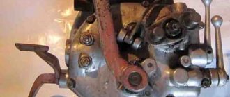
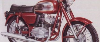
This article will be of interest to fans of rare motorcycle equipment.
In the electrical equipment systems of the Kovrovets-175A, Kovrovets-175B, Kovrovets-175V, M-104 motorcycles, the VP-150 scooter and some others, ignition is carried out as follows.
In the stator coils of the generator (there can be one or more of them in the ignition power circuits, depending on the type of generator), when the rotor rotates, an EMF is induced, creating a current of several amperes that flows as long as the breaker contacts are closed and the coil circuit is short-circuited to ground. When the contacts open, the stator coils are connected in parallel with the capacitor, together with which they form a shock excitation circuit. Damped oscillations with an amplitude of 200-300 Volts and a frequency of several kilohertz occur in the circuit. This alternating voltage is supplied to the primary circuit of the ignition coil and induces a voltage of 15-20 kV in its secondary circuit, necessary for spark formation.
To reduce the current through the breaker contacts and free them from the inductive load, it is necessary to close the circuit of the ignition power coils to ground using an electronic key, that is, switch the ignition system to electronic.
The choice of electronic ignition circuit depends on the polarity of the voltage on the generator at the moment the breaker contacts open.
To determine the polarity, you should connect a 300 V DC voltmeter to the “plus” of the ignition coil and to ground (the negative terminal of the device is connected to ground). Disconnect the breaker capacitor at this time. Set the engine crankshaft to the position where the breaker contacts begin to open. Then turn the crankshaft a few degrees in the direction opposite to normal rotation and lightly press the starter lever. If at the moment the breaker contacts open, the voltmeter needle deviates to the right, then the voltage on the generator is positive; if in the opposite direction, it is negative.
Fig.1
For a generator whose voltage is positive at the moment the breaker contacts open, the electronic ignition unit is mounted according to the diagram shown in Fig. 1. This block is a serial switch formed by transistors T1-T3. Diodes D1-D3 are used to decouple the base circuits of transistors. Resistors R1-R3 limit the base currents of open transistors, resistors R4-R6 ensure the transistors are turned off, resistor R7 limits the collector current of the switch transistors. At the moment of starting the engine, resistor R7 is short-circuited with button Kn1.
In an electronic key, transistors P210 can be replaced by transistors P209, P209A, P210A, P4B or P4G. When using transistors of type P4, the resistance of resistors R4-R6 should be increased to approximately 50 Ohms, so that when a voltage of 6.5-7 Volts is applied to the circuit, the current through the open transistors reaches 5A.
Resistor R7 is made of wire with a diameter of 1 mm with high resistivity. The capacitance of capacitor C1 can be in the range of 0.1-0.25 μF, the operating voltage is at least 300 V.
Fig.2
If, at the moment the breaker contacts open, the voltage on the generator is negative, the electronic ignition unit should be mounted according to the diagram in Fig. 2. It is assumed that for pricing purposes an ignition coil with an increased transformation ratio will be used.
Transistor T2 must have a good heat sink. Transistor T1 does not need a heat sink. Resistor R5 should be made of wire with a diameter of 1.5-1.8 mm with high resistivity. If the diameter of the wire is reduced, then it will be necessary to provide thermal insulation of the resistor from other parts, since it will heat up.
The ignition coil can have the following data: an open core, with a cross-sectional area of the rod of 3 - 4 cm2; the primary winding (wound first) is 65 turns of PEV-2 1.74 wire, the secondary is 20,000 turns of PE 0.06 wire. The ignition coil must have good insulation between the layers of the secondary winding, between the windings and between the primary winding and the core. The ignition coil must be enclosed in an insulating, moisture-proof housing.
Fig.3
In an electrical system with an alternating current generator, the power of the spark on the spark plug, the degree of incandescence of the lighting lamps, and the strength and timbre of the sound signal deteriorate with decreasing engine speed. This drawback can be eliminated if the electrical equipment system is switched to DC power by installing a rectifier and battery (Fig. 3). By the way, the VP-150 scooter has a place for mounting the battery.
In this case, the stator ignition power coils and the lamp and signal power coils are connected in parallel, having previously equalized the voltages at the outputs of both power circuits. In the G-38 generator of the Kovrovets-175A motorcycle, for example, the ignition power circuit consists of three coils of 57 turns each, connected in series, and the lighting circuit consists of five coils of 30 turns each. To equalize the voltages, you need to unwind about 20 turns from one of the ignition power coils. The generator of the VP-150 scooter has one ignition power coil containing 176 turns, and two lighting coils connected in parallel with 140 turns. In such a generator, you need to unwind 36 turns (about one and a half rows) from the ignition power coil.
Instead of D4 diodes of type D305, forming a bridge rectifier, diodes of type D231, D231A, D232, D232A, D233, D242, D243A, D244A can be used. The bridge must be assembled on an aluminum panel with a thickness of at least 3 mm, and the diode housings are separated from the panel with mica spacers.
If the electrical equipment system includes a ferroresonant voltage stabilizer (for example, as in the VP-150 scooter), then it is connected to points a and b; A semiconductor voltage regulator can be installed in the open circuit at point c.
Fig.4
When the electrical equipment of a motorcycle or scooter is switched to DC power, the electronic ignition unit is mounted according to the diagram in Fig. 4.
The Dr1 choke should have 180 turns of wire with a diameter of 1 mm with any insulating coating, wound on a core with an open magnetic circuit with a cross-section of 2-2.5 cm2.
When installing a rectifier and battery on Kovrovets-175 A, M-103, VP-150 and other motorcycles and scooters, the sound signal designed for alternating current power will have to be replaced with a direct current signal. If this is undesirable or not possible, the signal winding can be supplied with AC current through the normally closed relay contacts with a 6V actuation voltage. The relay coil is connected to the power source through another pair of normally closed contacts. In this case, the relay zooms, acting as a breaker.
Fig.5
The best effect can be obtained by using an audio frequency generator assembled according to the circuit in Fig. 1 to power the signal. 5.
In the G-38 generator of the Kovrovets motorcycle, the output voltage is regulated by selecting the parameters of the magnetic system and the stator winding. However, the effect is low: at crankshaft speeds of less than 2000 per minute, the voltage drops to 4 Volts, and at maximum speeds it exceeds 8 Volts. The VP-150 scooter is equipped with a ferroresonant voltage stabilizer, which also does not provide a good stabilization coefficient. The general disadvantages of ferroresonant stabilizers (except for the distortion of the curve shape, which in this case does not play a role) are the significant dependence of the output voltage on frequency fluctuations, reaching 1-2% for each percent of the frequency change (explained by the fact that the current-voltage characteristics of the capacitor and inductor when the frequency changes shift in different directions, resulting in a change in the characteristics of the circuit and a voltage drop), the dependence of the output voltage on the nature and magnitude of the load and, in addition, low efficiency - about 50-70%.
Fig.6
The circuit of the proposed voltage stabilizer, designed for current up to 10A, is shown in Fig. 6. The stabilizer consists of a phase shifter on transistors T2, T3 and a composite transistor T1T4. Zener diodes D1-D3, connected in the forward direction, stabilize the voltage at 2.5 Volts. The stabilizer is adjusted using potentiometer R2. Transistor T1 type P210 (or P209, P209A, P210A) must be equipped with a heat sink so that the case temperature at maximum load current and maximum input voltage does not exceed 50 ° C. The remaining transistors do not need heat sinks. Transistors of type P10 (T2 and T3) can be replaced with transistors of types P9A - P11A. Diodes D1-D3 can be of types D808-D814D.
Soviet transistors and their foreign analogues Repair of household appliances and electronics - professionals at Vremont.su