Maintenance
The owner can independently perform some maintenance procedures:
- check the motorcycle generator if the battery loses charge;
- set the gap between the breaker contacts;
- adjust the quality of the sound signal.
The need to inspect and adjust the wiring arises if:
- the motorcycle moves in the rain for a long time, as this causes oxidation of the contacts;
- a motorcyclist rides in an area with a lot of vegetation that damages wiring;
- The driver rides in snow in winter, which can stick to electrical wiring parts and damage them.
Self-check of the Planet 5 motorcycle generator in case of loss of charge
The cause of loss of charge in the IZH Planet 5 battery is most often a breakdown of the generator.
To check it yourself you need:
- multimeter device;
- straight screwdriver.
Step-by-step instruction
The following steps must be followed:
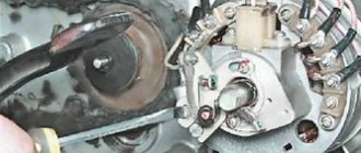
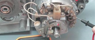
- Disconnect the wires from the battery and remove the generator cover.
- Disconnect the top 5 wires from the generator, first unscrewing their fastenings. In order not to mix up the wires during assembly, it is worth marking them.
- Measure the winding resistance using a multimeter in ohmmeter mode. To do this, you need to touch the body with one probe, and the other should be connected in turn to the 3 wires of the winding. There should be no short circuits, as indicated by the inscription on the multimeter screen.
- Test the resistance between the stator contacts: you need to touch them one by one with the multimeter probes. The value on the screen should be 8 ohms.
The presence of a short circuit in the 3rd stage or a discrepancy in the indicators in the 4th will indicate problems with the generator.
Photo gallery: stages of checking the IZH Planet 5 generator in case of loss of charge in pictures
How to correctly set the gap between the contacts of the breaker?
In order to set the gap between the breaker contacts, you will need:
- straight screwdriver;
- wrench 10;
- candle key;
- probe 0.4 mm thick (+/– 0.05 mm).
Next, you need to follow the steps sequentially:
- Place the motorcycle on a stand and place the gearbox in neutral.
- Remove the right crankcase cover and unscrew the spark plug.
- Using a 10mm wrench, grab the generator rotor mounting bolt and turn the crankshaft to a position where the contacts are as far apart as possible.
- Loosen the screw securing the contact.
- Place the probe between the contacts and adjust the tightening of the eccentric screw until the probe passes the contacts with little resistance.
- Tighten the contact fixing screw.
Photo gallery: adjusting the gap between the breaker contacts
Troubleshooting the audio signal and improving signal quality
Poor sound signal quality is mainly caused by improper adjustment.
The following tools will be needed for setup:
- wrench 7;
- a simple screwdriver.
Step-by-step instruction
To adjust, do the following:
- Loosen the locknut with a wrench.
- Turn on the ignition.
- Press the button to turn on the sound signal.
- Adjust the sound by rotating the adjusting screw.
- When the desired result is achieved, tighten the locknut.
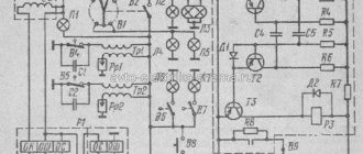
Electrical circuits of the ignition systems of the IZH Jupiter 5 motorcycle
1 - parking light lamp - A 12-4; 2 - high beam - low beam headlight - A 12-45:40; 3 - indicator lamp for generator operation - A 12-1; 4, 5 — speedometer scale illumination lamps — AMN 12-3; 6, 16, 17, 20, 23, 30 — lamps for the direction indicators of the motorcycle and side trailer; 7 - combination switch (right switch); 8 — brake light switch for the front wheel brake; 9 - breaker; 10 — spark plug; 11 — ignition coil; 12 - generator; 13 — rectifier-voltage regulator BPV14-10; 14 — brake light switch for the wheel brake; 15, 19 — side trailer clearance lamps — A 12-5; 18 — brake light lamp for side trailer — A 12-21-3; 21 — motorcycle brake light lamp — A 12-21-3; 22 — motorcycle rear marker lamp — A 12-5; 24 - battery; 25 - fuse; 26 — neutral lamp switch; 27 — ignition switch; 28 — sound signal; 29 — alarm switch (left switch); 31 — turn signal switch; 32 - high beam headlight control lamp - A 12-1; 32 — control lamp “neutral” — A 12-1; 33 - control lamp for direction indicator lights - AMN 12-3; Symbols on the BPV14-10 block (items 12,13): XI - “-” excitation windings; X2 - “-” battery (“ground”); ХЗ - “+” output to the control lamp; X4, X5, X7 - phases of the stator winding of the generator; X8 - “+” of the battery.
how to set the ignition on Jupiter 5 | Topic author: Valentina
Diana According to the instructions.
Maria According to the instructions. Do you think someone wants to copy two printed sheets with instructions here for you?!
Vadim 2.6 mm to TDC opening of the contacts - the 12 V light bulb is on - this means the beginning. You need to connect the light bulb to the breaker contact and turn on the ignition and turn the crankshaft if I remember the key is 11
Alexandra First, you set the gap on the Liliya breakers; to do this, you turn the crankshaft by the head of the Egor rotor mounting bolt. You determine the maximum opening of the contacts and set the gap to 0.6-0.8mm. Next, you will need the Stepan bushing and wrench from the Anastasia motorcycle key set. You start adjusting the timing from the right cylinder Anatoly. You install Stanislav instead of the spark plug of the right cylinder!), lower the knob into it, and turning the same rotor bolt you find TDC Inna That's it, stop! By turning the sleeve to unscrew, you align the cut of the sleeve with the notch on the collar. Now you need to lower the piston two notches below TDC Anton You return to the breaker. You unscrew the three screws on the crossbar securing the breakers and move them slightly counterclockwise, the contact opens. If you have a battery, you can connect a 12v 1sv light bulb directly to the wire on Valery’s breaker; if you don’t have a battery, we use *tissue paper*. So the piston is lowered below TDC by two notches, i.e. 2.5 mm, if memory doesn’t fail us, don’t turn it anymore!) The moment has come to find the beginning of the breaker break, and the light bulb will tell you about it. By moving the lower joint of the breaker traverse clockwise, the light goes out and lights up counterclockwise. So you need to capture that moment when the light bulb lights up! Lights up, fix the lower screw of the traverse. The left cylinder is adjusted in the same way. Now about the tissue paper. It is used as an indicator to determine the beginning of a rupture. We install it between the contacts of the breaker and determine the beginning of the break by free movement when the traverse moves.
I always set Victor by eye) 2mm to top dead center with a feeler gauge, and the contact gap by eye is a third of a millimeter. It worked flawlessly, the cylinders did not fail, I set it up and drove it for a year until I sold it. but it depends on experience. try to set it in different ways, gain experience, then you can also set it by eye when you get better at it) in the days of Jupiters there was no Internet, they set the ignition by trial and error
Installing a contactless ignition system on Izh Jupiter-5 is a fairly current topic. When setting up a BSZ on Izh Jupiter-5 BSZ, it is necessary to take into account a number of nuances that can significantly affect the operation of the equipment used.
What advantages open up to users who decide to install electronic ignition on the Izh Jupiter are described below.
Most modern motorcycles are not equipped with cams, that is, breakers. Why did the manufacturer consider them unnecessary for currently sold models? The answer is quite simple. This system is not very reliable.
Many parts used in the system are sources of trouble. The most common ones are listed below:
- The ignition gaps change their original position while driving a few days after adjustment;
- A spark occurs every once in a while, since the contacts regularly burn out;
- Capacitors are constantly damaged;
- Low spark power;
- If you add two or three volts to the battery, it is quite difficult to start it. Such ignition is the reason for constant repairs while driving.
This is noticeable at idle. The speed of their passage has noticeably increased and the unnatural twitching has disappeared. The characteristic knocking sounds of iron components in the crankcase and accompanying detonations also disappeared. The handling of the Jupiter 5 motorcycle will improve simultaneously with the time it takes to gain speed.
"Sores"
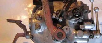
Assembling the Izh Planet 5 box
There are already three sores in the planet gearbox:
- Oil leak from the intermediate shaft plug
- Poor gear engagement in first gear
- Constantly loosening the bolts securing the gearshift shaft stop
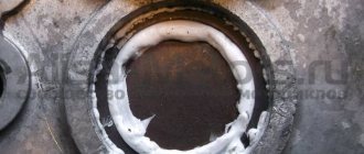
I solve the problem with oil leakage very easily and simply: I take out the retaining ring; I remove the intermediate shaft bearing, degrease the plug, retaining ring, mounting hole, then apply sealant to the outer edge of the plug, put it in place and immediately press it with the bearing and voila - the leak is eliminated!
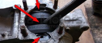
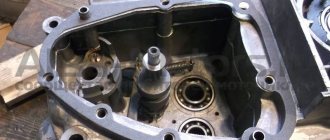
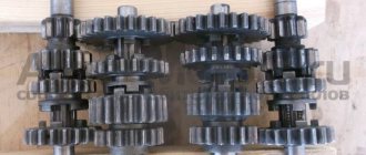
Due to a factory defect, the gear-carriage for engaging the first-third gear does not fully engage the first-gear gear with its cams, but only in a small part, barely catching the gear with its cams, which is why the edges quickly wear out and the first gear begins to knock out.
This moment is clearly visible in the photo. For this particular gear, the hook was no more than a couple of millimeters. It is difficult to cure this “sore”: from the side of the first gear gear, you need to grind the end of the intermediate shaft by 3-4 mm and, using adjusting washers, move the first gear gear to the carriage. I don't see any other way.
During operation, the bolts securing the stop are constantly unscrewed, either due to vibration or something else - they are unscrewed and that’s it, no matter how you tighten them... Even special lock washers do not help. I struggled with this disgrace for a long time using all the traditional methods known to me and came to the conclusion that the best solution to this problem is red thread locker. Feel free to put bolts on it and get rid of this problem once and for all.
Photo report: Assembly of the box of the Izh-Planet motorcycle 2, 3, 4, and fifth model
Disassembly and assembly of the gearbox
What I like about the Planetovskaya checkpoint is that it can be disassembled and repaired without disassembling the engine or even removing it from the frame: directly in place, without even draining the oil: we lay the motorcycle on its side and repair it - this is actually in terms of repair and the service is very convenient.
The second pleasant point is that the gear ratios of the first second and third gears in the “Planetovskaya” gearbox can be changed at your discretion by simply selecting gears and shafts from other models of motorcycles of the “Planetovskaya” series. Thereby making the desired gear faster or more high-torque.
Disassembling and assembling the Izh-Planet 5 box
VAZ 2110 gearbox operation diagram
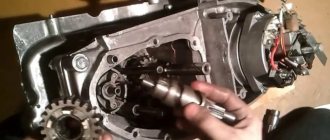
First, you will need to completely dismantle the clutch, starting device and motor transmission, and also drain the oil. After these manipulations have been carried out, you can begin to remove the gearbox. In the area of the right side of the motor, unscrew the eight mounting screws. The driver's footrests, foot brake lever, and crankcase cover on the right side are removed. The clutch cable is disconnected and the ball and pusher of the input shaft are removed. After this, the circuit is disconnected. Designations in the photo below: clutch discs (1,3), lower disc (2), inner drum (4), nuts (5, 6).
The crankcase cover is placed on the prepared rags or paper. You can pull it out by grabbing the star with your hands and pulling it towards you.
If the element does not budge, look at the worm shaft support washer, which may have become warped. Place tweezers or a knife into the hole between the crankcase and the cover, and then straighten the part
When dismantling the housing, a couple of washers may fall out. The second element is slightly thicker and is mounted on the copy shaft. They must be signed and put away with the rest of the spare parts.
Final stage
Next, the second and third speed gears are removed from the input shaft, after which the input shaft is dismantled. To do this, you will need to carefully knock it out using a stopper and a light hammer. The upper and lower forks are removed.
Next comes the intermediate shaft assembly. Using a screwdriver or other suitable tool, bend the clamp with the neutral indicator and carefully pull out the worm wheel. On its far side there are shims that could stick to the crankcase. They need to be collected and stored with the rest of the removed parts. Next is the turn of the copy shaft. Check the edges of the shaped sockets in which the guide forks move. They should not have chips or dents. We unscrew a couple of screws securing the switching mechanism, which is also removed. Now you can replace unusable parts and assemble the Izh-Planet 5 gearbox according to the scheme. The figure below shows: retaining cap (1), bolt (2), crankshaft sprocket (3), double-row chain (4), clutch drum (5), input shaft (6).
Malfunctions and clutch adjustment of Izh motorcycles
There are two possible types of clutch malfunction: incomplete disengagement of the discs and slipping. If the motorcycle is slipping, it will not develop speed as the crankshaft speed increases. The reasons for this malfunction may include: wear of the discs, insufficient spring pressure due to loss of elasticity or loose adjusting nuts, incorrect adjustment of the clutch mechanism. When the clutch is not fully disengaged, the motorcycle wheel continues to rotate while the control lever is fully pressed. This may also be due to incorrect adjustment, or this malfunction may occur when thick oil is used, especially in cold weather. First of all, if you discover one of the clutch malfunctions, try to eliminate it by correct adjustment. First, you need to adjust the gap in the shutdown mechanism; this is done using the adjusting screw located on the right engine cover. To do this you will need a screwdriver and a 13 mm wrench. Using a wrench, loosen the locknut and use a screwdriver to tighten the screw until it stops, and then turn it in the opposite direction half a turn - one turn. Tighten the locknut with a wrench. Secondly, after this, adjust the free play of the lever using the cable adjusting screw on the left handlebar handle. It should be within 5-10 millimeters. The correct clutch adjustment can be checked in this way: place the motorcycle on a stand, engage first gear and try to manually turn the rear wheel with force. If the adjustment is correct, you will not be able to do this. Now you need to perform one more check: to completely disengage the clutch. To do this, in the same position (motorcycle on a stand, rear wheel not touching the ground), start the engine and engage first gear. Then fully depress the clutch control lever and apply the rear brake, the wheel should stop. Release the brake, the clutch is depressed, and the wheel should remain stationary if adjusted correctly. If it starts to rotate when the lever is pressed, you need to loosen the adjusting bolt on the right side of the engine.
To check the ease of movement of the clutch cable in the sheath, press the lever and release sharply. The lever should spring back to its original position. It may be worth lubricating the cable with a few drops of liquid oil, such as Autol.
Assembly
In a carefully washed and prepared for assembly crankcase we place the input shaft, the first gear gear and the follower shaft with pre-selected shims.
We put a fork on the gear-carriage for engaging the second-fourth gear (it is smaller than the gear-carriage for engaging the third-first gear, you can’t go wrong) as shown in the picture. We put the gear on the input shaft and insert the fork pin into the upper groove of the follower shaft.
We put a fork on the gear-carriage for engaging the first-third gear, as shown in the picture, place it on the first gear gear and insert the fork pin into the lower groove of the copy shaft.
We install the fork guides in their places (with grooves towards the clutch basket). By the way, if necessary, the “Planetovskaya” gearbox can be assembled and disassembled without disassembling the clutch basket and without removing the guides. But to do this, during installation you will have to pull the tracing shaft towards you a little, insert the pins of the forks into the grooves and after that, remove the locking bar and push the tracing shaft all the way.
Install the intermediate shaft.
On older engines, the end gear is installed separately. On later ones, it is made integral with the intermediate shaft.
We fill the return spring of the gear shift shaft as shown in the picture.
We check the functionality of the gearshift shaft pawls: compress and unclench them several times
We pay special attention to their working edges: they should be sharp and not licked. And don’t forget to check the spring that compresses the pawls: it must be of the correct shape and ensure the elasticity of the pawls’ movement
We squeeze the pawls and install the gear shift shaft in its place.
We rotate the tracking shaft with the mark on the body towards the gear shift shaft and so as not to miss the mark during installation, we cover the gap between the teeth opposite the mark of the tracking shaft with lithol or paint it. It will be more noticeable this way.
We look for a mark on the sector and when putting the sector on the gear shift shaft, we combine the mark on the sector with the mark on the tracking shaft body: the tooth opposite the sector marks should strictly fit between the teeth opposite the mark of the tracking shaft.
To ensure that our marks do not get lost during installation, we tie together the sector and the copy shaft with ordinary sewing thread.
We put standard thrust washers on the input and follower shafts and insert the guide bushings of the gearbox cover into place.
We degrease the surfaces, apply sealant, lay the gasket, install the cover and tighten the mounting bolts with the maximum possible force. We adjust special washers under the bolts marked with yellow arrows.
After tightening the gearbox cover, we check the axial play of the primary and secondary shafts. Normal: 0.2-0.4mm.
If the play is greater than normal, remove the plate, seat the bearing and adjust the required number of shims under it.
Comments • 0
why does the box click
at the age of 13 I already knew this
I have an Izh pl 4 4th gear with jerks
Guys, those who understand Izh Planet 5 don’t give me the speed, but when I put it in 2nd gear or 3rd, the box starts to rumble and squeak, this is also behind this plate under the clutch basket or this and for something else, please help, otherwise it’s the season motorcycles opens but my moto doesn’t work properly
Or maybe this happens with 3rd gear?
Don’t get carried away with the grab itself, you shouldn’t overwhelm it, but the planet’s checkpoint has been collected and adjusted once and forever, simple and reliable good luck
nothing to say
And then I changed gears because of a broken tooth.
Well explained, I think anyone can get it. Like
And if on planet 4 2 the gear went out 2 times, what could this mean?
Good afternoon, what is the name of that thick washer that sits on the input shaft under the secondary shaft? I disassembled my box, I don’t have one, because of this there is play in the primary and secondary shafts. The stores don’t understand me; they offer me anything except what I need! Maybe there is an alternative, put another washer there, what are its diameters and thickness?
Repair
Once the unit has been gutted, you can begin to determine the parts that need to be replaced. As a rule, you have to buy a set of shims, a set of gaskets and sealant. This is the case if there are no more serious damage. Once you have decided on the elements to be replaced, you will need to adjust the worm shaft axis, and after final assembly, the clearance along the axis of the primary, intermediate and secondary shafts.
Adjusting washers are placed on the far ledge of the copy roller; they should be lubricated with a special compound. A support washer is mounted on the near edge, and the shaft is put in place. It should be turned so that the neutral sensor with its protrusion fits into the deepest groove. Then, using a ruler (without the gearbox cover yet) on the plane of the crankcase, measure the gap between the washer and the dipstick. It should be no more than 0.2 mm. Depending on the indicator, regulators are added or removed. If it is impossible to accurately set the gap, it is better to make it smaller.
Important
When performing these operations, follow the mark in the middle part of the sector. It should coincide with a similar mark on the shaft. The last step is to install the crankcase cover. If the work is carried out correctly, it will sit in its place without problems.
It is necessary to ensure that all rods and shafts coincide with their original mounting sockets. They should rotate freely without creaking or jamming. Use moderate force when tightening the screws as the threads in a soft metal crankcase can easily be stripped. All fasteners are tightened evenly to avoid distortion.
Source
When is it necessary to repair and adjust the gear clutch on an Izh motorcycle?
Regardless of the amount of experience the motorcyclist has, the feelings regarding gearbox malfunctions are almost the same:
- At first it seems that the clutch is slipping slightly. After two or three days, confidence appears - yes, it is slipping, because as soon as you add speed, the acceleration rate lags behind the engine speed level. The breakdown is especially obvious when moving uphill.
- The clutch “leads” or the clutch is incompletely disengaged when the control lever is depressed. In such a situation, the disks of the assembly remain pressed against each other and do not stop transmitting torque to the gearbox. You can finally verify such a breakdown after lifting the rear wheel - it continues to rotate in this situation.
If you want to know how to adjust the clutch on an Izh-Jupiter 5 motorcycle, then information about the reasons causing the listed factors would be useful:
- Use thicker oil in winter.
- Weakening of pressure springs.
- Worn clutch discs.
- Wear of clutch control mechanism elements.
In most cases, if signs of slipping or incomplete disengagement of the clutch are detected, a simple adjustment of the mechanism is required. To do this, it is enough to have a “13” key and a slotted screwdriver.
How to adjust a motorcycle clutch?
As always, we delve into theory.
Junker's clutch type is multi-disc in an oil bath. On the left, on the gearbox shaft, sits a basket with alternating disks, thin steel and thick getinaks. They are pressed against each other using 5 (or 6) powerful springs. Getinaks disks are connected to the basket (and, through the motor chain and 2 sprockets with the crankshaft), and steel ones are connected to the gearbox shaft (and, through the gearbox, actually to the wheel). The springs are so powerful that the entire power of the engine, without slipping (and the disks are all in oil) is transmitted to the rear wheel. Next, when you press the clutch lever, the cable pulls the lever (it sits on the right engine cover - look), which pushes the steel rod (it passes through the axis of the drive sprocket, you can take it out and turn it in your hands), and this rod rests on that part a basket with disks, which is connected to the getinax disks, and they, overcoming the resistance of the pressing springs, move away from the metal disks. That's it, the clutch is loose. The engine with its getinaks disks rotates on its own, the steel ones with the gearbox stand still. Attention! There is more than one push rod. There are 2 of them, and between them there is a ball from the bearing (eliminates rotational force). Easily lost! Be careful when disassembling, otherwise you will end up with a failed clutch.
Now about the adjustments.
The clutch is adjusted NOT ON THE HANDLE, but by changing the force of pressing the discs against each other. The free play of the cable is simply selected on the handle. The force of pressing the disks against each other is regulated by preloading the springs, on which, for adjustment, “fungi” with a groove for a large flat-head screwdriver are put on. Access to these “fungi” appears by unscrewing the cap on the left engine cover (the hole through which you pour oil into the engine). And not to all of them at once, but only to a part – i.e. to adjust everything you will have to rotate the crankshaft with a kickstarter
IMPORTANT! All springs must have the same preload! Those. all mushrooms twist at the same number of revolutions
Or rather, half a turn - a turn is too large an adjustment step.
What to do if the clutch slips?
1. Make sure that the clutch handle has free play and that you have not unscrewed the adjuster on the handle so that the clutch is constantly depressed. 2. Open the left cover (no need to drain anything, at the same time check the oil level in the engine on the dipstick - it should be between the marks) and evenly, carefully tighten all the fungi half a turn. We start the engine, check the clutch operation, if it still slips, turn it off and repeat the procedure. At the same time, we look at the condition of the teeth on the textolite disks - if they break off on some disk, then it begins to rotate with the steel disks and the clutch operates. Good official Hyundai dealers will help you make the right decision. For an office move, movers are indispensable, I recommend Best-Loader.Ru. Wheel storage in Moscow. What to do if the clutch does not disengage?
1. See paragraph 1. higher. 2. See point 2 above, only the fungi are unscrewed half a turn. Well, the reasons for a driven clutch are natural wear of the discs, weakening of the springs, breaking of the protruding teeth on the getinaks discs, pulling out of the cable and LOSS OF THE BALL when repairing a motorcycle.
Now about what a semi-automatic clutch is.
When you change the speed, the shaft on which the gear shift paw sits turns, and with its fork protruding into the right cover, it presses on the clutch lever (the same lever to which the clutch cable fits and which presses on the steel rod), and thereby duplicates the pressure on the clutch handle by hand. And don’t blaspheme the semi-automatic in vain! A very necessary and useful thing! Firstly, your clutch cable has simply never broken on the road - it’s impossible to get going without a semi-automatic vehicle. Secondly, on the road, starting from 2nd speed, I never used the manual clutch at all - there was no need. When changing the speed, I simultaneously disengage the clutch, change the speed and smoothly engage the drive! (You make one move, oh IT makes 3!
) The only thing is that it’s inconvenient to get going with a semi-automatic vehicle if you’re not used to it, but it’s quite possible.
Functional purpose of the gearshift clutch
Before you adjust the clutch on the Izh-Jupiter 5 motorcycle, it’s a good idea to understand its purpose and principle of operation. The essence of the transmission clutch:
- Ensuring the transmission of torque from the large gear of the motor transmission to the gearbox input shaft.
- Short-term separation and smooth connection of transmission elements to each other.
Izh motorcycles were equipped with a mechanical clutch, the operation of which is based on the friction force between the driven and driving disks. It is a multi-disc design operating in an oil bath - a classic arrangement that the Izhevsk Machine Plant used until 2008. Working in tandem, the main chain drive and four-speed gearbox are reliable and proven by many generations of motorcyclists.
Original and color wiring diagram for IZH Planet 3
4 years after the appearance of the second Planet (1966), the factory workers made a number of changes to its design, designed to improve the technical parameters and appearance of the motorcycle. This is how IZ Planet 3 was born, which became a real symbol of freedom for many of our compatriots.
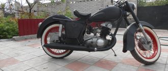
Despite its advanced age, IZH Planet 3 still serves its owners well
Differences from the second Planet
For many modern citizens, the information that domestic motorcycle manufacturers worked tirelessly to improve their models in an era of total shortages may come as a surprise.
Note! The fact takes place, moreover, it is supported by official documents, in particular 1970N04P16-17 - this is the outgoing number of the factory newsletter, which described the changes made. In the photo - official materials of the Izhmash Design Bureau
In the photo - official materials of the Izhmash Design Bureau
The new generation motorcycle received:
- Direction indicator lights are a first in domestic practice;
- Semiconductor relay for controlling direction indicators (installed in the headlight);
- New size of wheels and tires (3.50x18 versus previous - 3.25x19);
- New brand increased capacity battery (old one on IZH Planet 2 - ZMT-6);
- And, of course, more engine power. The power unit now developed 18 hp.
Modifications
But the creator engineers did not stop there and, having released the five-millionth car from the production line, presented a modification of the IZH Planet 3-01.
Mirror and safety arches are the distinctive features of the new modification
Among the innovations it should be noted:
- Rear passenger footrests;
- Roll bars;
- Rearview mirror;
- New steering wheel design.
IZH Planet 3-01 with wide wheels of smaller diameter - “rural version”
Distinctive features of electrical equipment
The wiring diagram used on IZ Planet 3 was traditional, and the main parameters of the electrical equipment are presented below in the table.
| Ignition system | Battery, ZMTR-10 |
| Mains voltage | 6 volts |
| Electricity source | Generator G-35M7 (later replaced by a modified G-36M8), 45 W |
| Ignition coil | IZH 56 |
| Voltage regulator relay | IZH RR-1 |
| Electrical wiring IZH Planet 3 | Single-wire, with “-” output to ground |
Colored original diagram (clickable)
Lighting devices
The following lighting devices were installed on the IZH Planet 3 motorcycle:
- Left and right direction indicators with A6-6 lamps;
- Turn signal switch P201;
- Turn signal relay RS-419;
- Brake light bulbs A6-15;
- Side light bulbs A6-2;
Appearance of instruments and controls
- Light mode switch with sound signal button P200;
- Transmission position sensor (neutral) with warning lamp A6 0.25;
- Headlight lamp A6-32+32;
- Indicator lamp A6 0.25 generator operation;
- Side light lamp A6-2 (front);
- Speedometer scale illumination lamp A6-1;
Headlight lamp and direction indicators For connoisseurs of “antiques” - the original diagram from the instruction manual
Lighting devices for models with a stroller
Added to the existing list:
- Stroller brake light lamp A6-15;
- Stroller size lamp A6-2;
- Right direction indicator for stroller A6-6;
- Front side light of stroller A6-2.
Option with stroller
In the presented video you can watch the repair of an old motorcycle, which received a new life in capable hands. According to the author of the video, complete restoration cost him the equivalent of $130. Moreover, he did most of the work with his own hands.
Finally
This is IZH Planet 3 - a symbol of the era of the seventies. If it's still collecting dust in your shed or garage, repair it and hit the road. Believe me, it will give odds to modern scooters in terms of reliability and endurance. Good luck!
Features of electrical equipment
The wiring diagram of IZH Planet 4 is almost completely copied from the Jupiter model that was the first to appear on the factory assembly line.
The only differences are that:
- The Planet family has one working cylinder, and accordingly the ignition system is designed to ensure its operation;
- The IZ Jupiter family, unlike the Planet, has 2 working cylinders; accordingly, the wiring diagram has additional repeating elements.
Headlight
IZH Planet 4 is equipped with more advanced lighting devices:
- Headlight type "European beam" FG137V with glass with an asymmetrical pattern;
- Low beam mode with lamp A12-45 + 40 W;
- Modern direction indicators type 16.3726 (lamp power - 25 W).
Photo of IZH Planet 4 model 1986
Thanks to the modernization of the lighting system, as well as the configuration of the motorcycle:
- battery 6MTS-9;
- high power alternating current generator 100 W,
The illumination of the road in the flow of traffic has significantly improved, and traffic on public roads has become safer. At the same time, the price of the motorcycle did not change significantly, which brought its sales to a new level of popularity.
Contactless ignition system
The motorcycle used a new contactless ignition system, the operating principle of which was based on the following operating algorithm:
- The generator rotor generates pulses when rotating;
- The storage capacitor is charged through diodes (in the diagram below indicated as VI, V5), as well as through a limiting resistor (R1);
- Passing through the diode (V6), the electrical signal from the sensor winding (3) enters the thyristor (V4);
- After it opens, the charged capacitor (C1) transfers the accumulated charge to the ignition coil (primary winding - 4);
- Under its influence, a high voltage pulse is induced in the secondary winding;
- Through the high-voltage wire, the central electrode of the spark plug receives a charge;
- A spark between the electrodes ignites the air-fuel mixture in the motorcycle engine cylinder.
The factory instructions contain the original diagram of the contactless ignition system
The electrical wiring of the IZH Planet 4 motorcycle, due to the peculiarity of the contactless ignition system, has differences in the layout of the main components:
- The electronic unit of the stabilizer and ignition system is placed in a single housing;
- It is equipped with two plug connectors;
- In order to increase reliability, the block is filled with polyurethane foam (non-separable version);
- Its operating parameters are designed to provide a light signal circuit voltage in the range of 11.5 – 14.5 V.
In addition, the use of a 12-volt circuit led to the division of the ignition system into three electrical circuits that differ in voltage levels:
- A high-voltage circuit consisting of an ignition coil, a spark plug, a spark plug tip and a high-voltage wire;
- Storage capacitor charging circuit, consisting of a charging winding, connecting wires with plug connectors, BCS and the primary winding of the ignition coil;
- The sensor circuit, consisting of its winding, connecting wires and plug connectors.
Generator IZH Planet 4
A more advanced generator began to be installed on the new model of the Izhevsk Motor Plant, capable of serving the increased needs of the electrical equipment system, in contrast to the wiring diagram of the IZH Planet 3.
Original factory circuit diagram of the IZH Planet 4 motorcycle generator
Among the design features it is worth highlighting:
- Eight coils placed in the stator slots;
- Serial connection diagram;
- Coating of coil windings with insulating varnish;
- Original fastening to the stator, made using washers and bent petals.
To identify faults with your own hands, you need an ohmmeter or a universal tester, which can be used to measure the resistance of the windings:
- If the values of the measured resistances differ significantly, it is necessary to inspect the generator stator to detect broken winding leads;
- The reason for unstable operation may also be their short circuit. If possible, identified faults are eliminated by soldering.
IZH Planet clutch malfunction
Possible malfunctions that may occur during operation of the IZH motorcycle. Let's start with clutch slippage. This error indicates that the drives are slightly pressed together.
There may be several reasons:
- Incorrect setting
- The springs have lost their former elasticity
- The discs are worn out and become thinner
- Wear of drive parts
Clutch wires. This is when the lever is pushed all the way and the clutch is not completely disengaged. The discs are not evenly weakened in places that are in close contact with each other.
The main reason is the springs that compress the discs.
The clutch of the Izh-Planet motorcycle, no matter what model: be it “Izh-Planet-Sport”, “Izh-Planet 2″ or even Izh-Jupiter” can rightfully be considered a completely reliable and durable unit. But it has its own design flaws, which are a common cause of breakdowns.
Since their first appearance, the Izhey engines, although not as often as we would like, have been modernized. After all, the power of the Planet-5 engine has almost doubled compared to the same Izh-49, and even more so in some models (Izh-Planet-Sport).
The power was increased - that’s good, but the designers didn’t pay enough attention to the clutch. As it was on the Izh-49, it migrated almost unchanged to later Izh models.
This is where the “root” of all problems grows: we increased the engine power - well done! The stroller was attached - even better! The compression has been increased - where would we be without it? But they forgot about the clutch and ratchet mechanism. But the load on it has increased significantly compared to its progenitor - this is where frequent problems arise in its work.
By the way: later Izhey models began to be equipped with a clutch with a reinforced motor chain and an improved design of the kickstarter ratchet mechanism, the so-called “daisy”. Of course, such an “innovation” did not bring much effect: just as the ratchet on the “Planets” tore, it continued to tear. As the motor chain stretched literally in one season, it continued to stretch...
Improved ride quality
The icing on the cake, and in our case the final touch of tuning, is the improvement in driving performance. Some of the tuners approached this issue earlier when they sawed the frame of their motorcycle or raised the tail of a future crossover. For the rest, first of all, you should get rid of your original tires. Among its advantages, only wear resistance can be noted, for which you pay with your safety. It is both universal and useless. The lugs are practically useless; if they get into a mess, under normal conditions on the highway it is noisy, but relatively holds the road, turning into a killer on a wet highway.
Therefore, without hesitation, we throw it away and purchase road, cross or all-purpose tires, based on your requirements. The second point is the suspension. If everything is generally clear with the rear shock absorbers, they are extremely reliable and, in addition, have stiffness settings, then the front fork does not leak only for those who have chosen a different brand. There are two ways to get out of this situation. The first is to add thicker oil. The second is to carry out a complete overhaul of the feathers and replace all parts. Both options do not last long, so the most demanding owners simply change the fork to an imported one, while the rest endure all the shortcomings of their iron horse.
Purpose of the clutch IZ Planet and IZ Jupiter
Clutch - the name speaks volumes about the job it does. In our case, the crankshaft engages the gearbox of the IZH Planet and IZH Jupiter engines. The connection should occur smoothly without jerking, this is necessary to start moving and smoothly change gears. In case of heavy loads, it protects engine parts from damage. The clutch is located in the left half of the crankcase, under the left engine cover.
To get to the clutch, you need to drain the oil and remove the cover with the gasket, first remove the levers and unscrew the mounting bolts.
The basket is constantly in working condition, the discs are tightly compressed by springs.
The motor transmission consists of two sprockets. The small drive is located on the crankshaft. A large star driven on a drum. The connection is made by a motor chain.
The engine gear ratio is 2.17 for all single-cylinder IZh models. For IZ Jupiter, the gear ratio is 2.57.
When assembling the motor transmission, the planar arrangement of the stars is controlled. No more than 0.4 millimeters are allowed.
Switching off occurs using a special device. The shutdown mechanism is installed in the right engine cover. This mechanism is used to make adjustments.
Installation of the cylinder-piston group
How to change the timing belt on a VAZ 2105 yourself: detailed instructions
It is not advisable to remove the gearbox cover until the sealant has dried; there is no need to rush in this matter. It’s better not to rush things and install the cylinder while the sealant dries.
Add some motor oil:
- into the upper head of the connecting rod
- lower connecting rod head
- into both oil channels of the crank chamber
To improve lubrication, it is advisable to drill holes in the piston bosses. But you don’t have to drill - it depends on your desire.
Install the piston pin retaining ring into the boss. Before installation, it is advisable to bend the locking ring a little and be sure to check how it fits after installation:
- If the retaining ring dangles, straighten it or replace it with a new one.
- If the retaining ring is not completely flat, replace it with a new one.
We heat the piston with a hairdryer and, using a mandrel, drive the finger into the piston so that it comes out no more than 5-6mm.
We look for an arrow-shaped mark on the bottom of the piston.
We orient the piston with the arrow towards the exhaust port of the cylinder (“towards the exhaust”), put the piston on the connecting rod, hammer in the piston pin and install the second retaining ring.
We insert the rings into the cylinder and measure the gap between the locks with a feeler gauge:
- If the gap is less than 0.3-0.45, sharpen the ring locks with a file
- If the gap is greater than 0.3-0.45, install new rings; if that doesn’t help, bore the cylinder to the repair size
To improve the wearability of the rings and reduce noise from engine operation, it is advisable to chamfer the edges of the rings. If hunting gets too much trouble: place the ring on a flat surface and use a file to slightly round the edges.
We put the rings on the piston, fill the piston with the rings with oil, install a gasket under the cylinder (preferably with sealant), tighten the rings with a clamp. We cut the clamp out of tin and from the same tin we bend the bracket with which we will fix it.
We put on the cylinder.
After the rings go into the cylinder, unfasten the clamp, lower the cylinder and screw it to the crankcase.
We turn the crankshaft several times and if the piston moves in the cylinder easily and without grinding, lower it down a little, pour a little engine oil into the cylinder, install a new gasket on the cylinder and screw the head on.
We install the additional crankshaft support bearing in its place, place the required number of adjusting washers on top and secure it with a retaining ring. The adjusting washers must ensure axial play of the crankshaft within 0.1 mm.
Before installation, sealed bearings must be opened! The usual 304 goes here.
On the other side of the crankshaft we install a flange with a main oil seal.
Pay attention to the oil channel through which oil flows to the right main bearing of the crankshaft. According to the good old collective farm tradition, this channel is sealed with sealant and the lubrication of the bearing stops. To avoid this problem, place the flange dry without sealant and everything will be fine
To avoid this trouble, place the flange dry without sealant and everything will be fine.
After the sealant has dried, you can begin adjusting and assembling the gearbox and replacing the clutch basket.
Numbers of bearings and oil seals for the Izh-Planet motorcycle engine 2, 3, 4 and fifth model.
- Crankshaft main bearings 2505k
- Additional crankshaft support bearing 304
- Right oil seal IZH-yu sb. 1-48-3
- Left main oil seal IZH-yu sb. 1-50
Most common problems
Most often, the motorcycle in question loses or shifts poorly in second gear. This may be due to careless turning on of speeds. For example, when picking up high speeds in first gear without neutral, when engaging the second speed gear, an impact occurs, which contributes to intensive wear of the unit. Therefore, it is not recommended to “spin” the first speed too much. If, nevertheless, problems with the second position continue, there are several options for resolving them.
In some cases, the simplest method will help, without completely disassembling and then reassembling the Izh-Planet 5 box. It is necessary to place the motorcycle on the right side, and then remove the kick starter and gear shift foot along with the shaft. Next, the crankcase cover and clutch basket along with the discs are dismantled.
When the gears of the box wear out, the meshing of the teeth deteriorates. In turn, this leads to slipping, jerking and failure of the second gear. Another reason could be wear on the input shaft bearings. Since it moves slightly to the left due to vibration, it is necessary to move it into place with light blows using a mallet. The installation of washers of suitable diameter will allow you to fix the element in the desired position. Then the bearing stopper and other dismantled parts are reassembled in the reverse order.
Completion
Above is the assembly of the Izh-Planet 5 box in detail. After tightening the clamps, you need to check the drive sprocket again for correct rotation. At the end, a ratchet with a spring, a clutch drum bushing and itself are installed, and the chain drive is connected to the drive sprocket, and transmission oil is poured into the box.
The Izh Planet 5 gearbox is four-speed, three-shaft with constant mesh spur gears and foot-operated gear shifting. Switching is carried out using a copy shaft, which is located inside the box; the shift fork pins fit into its grooves. The copy shaft rotates from the shift selector, which in turn is connected to the foot lever. The secondary shaft is hollow and fits onto the end of the primary shaft. The main gear sprocket is located on the secondary shaft. The gearbox is located in the same crankcase with the motorcycle engine, together forming a single power unit. The gearbox is lubricated by oil poured into the engine crankcase. The IZH Planet 5 gearbox can be disassembled without removing the engine, however, for complete disassembly and greater convenience, you can remove the engine from the motorcycle frame. Today we will look at disassembling the Izh Planet 5 gearbox step by step.
Drain the oil from the motorcycle crankcase by placing it on a stand. Then, after unscrewing the bolts, remove the right engine cover as well as the gear shift levers and kickstarter. Having disconnected the chain casing from the box, we separate the chain links. We take out the clutch rod, and then use a large screwdriver or chisel to bend the sprocket retaining washer. Now you need to unscrew the sprocket nut; to do this, wedge the sprocket between its teeth and the engine crankcase with a suitable metal object, preventing its rotation. The thread on the nut is left-handed, so you need to unscrew it clockwise using a 36mm wrench. Use a screwdriver to unscrew the seven screws of the box cover, remembering the length of the screws (it is not the same) and do not lose the aluminum sealing washers under the heads of the two lower screws.
Using a universal puller, remove the secondary shaft sprocket. Through the gap formed between the cover and the crankcase, we hold the gear sector of the starting device. If this is not done, the sector moves behind the cover and it, warping when the puller is tightened, may crack. Do not “help” the puller by wedging the gap with a screwdriver or similar tool. This will damage the cover gasket and, most importantly, cause dents to form at the junction of the cover and the crankcase, which will lead to oil leakage.
Remove the gear selector from the axle.
Remove the shift shaft along with the ratchet mechanism.
Lifting the follower shaft, remove the pin of the shift fork for 2nd and 4th gears from its groove. Remove the fork from the rod, and from the primary gear the 2nd and 4th gears and the washer.
Remove the intermediate shaft.
Use a screwdriver to pry the lock lever away from the tracing shaft. Remove it by removing the shims and noting their location.
Remove the 1st and 3rd gear shift forks from the rods and gears of the 1st and 3rd gears. The plugs are not interchangeable, so remember their placement.
Remove the first gear. Pay attention to its position in the crankcase.
Using two screwdrivers, slightly open and remove the split retaining ring of the gear from the groove of the input shaft. Remove the retaining ring, thrust washer and gear from the primary.
Unscrew the sprocket nut and remove it.
Remove the secondary one from the cover, while remembering that the bearing here is a cageless one, be careful not to lose the rollers!
If the ball bearing of the intermediate shaft is severely worn or damaged, remove it from the cover. The bearing is not a tight fit and usually comes out of its seat easily.
Separate the cover gasket.
Inspect and wash all parts in kerosene. If severe wear occurs, replace. Thoroughly clean the bottom of the Izh Planet 5 gearbox housing. Attach the roller bearings of the secondary shaft, generously lubricating the shaft with thick grease. Reassemble the gearbox in reverse order. If the gasket is torn, replace it. Be sure to align the marks on the track shaft on the gear side and the gear shift sector. First, assemble the box without covering the gasket with sealant to make sure the box works correctly. Speeds should switch clearly and correctly, and parts should rotate without clicks or jams. After making sure that the operation is correct, remove the cover again, degrease it with acetone or gasoline where it contacts the crankcase, and lubricate the gasket on both sides with a thin layer of sealant. Do not use sealant alone for sealing without a gasket! The axial clearances may be disrupted and the box will not work correctly. Tighten all bolts in a crisscross pattern. Fill your Izh Planet 5 motorcycle with oil and check for leaks.
Do you know what types of threaded connections are used on motorcycles?
Repair
Once the unit has been gutted, you can begin to determine the parts that need to be replaced. As a rule, you have to buy a set of shims, a set of gaskets and sealant. This is the case if there are no more serious damage. Once you have decided on the elements to be replaced, you will need to adjust the worm shaft axis, and after final assembly, the clearance along the axis of the primary, intermediate and secondary shafts.
Adjusting washers are placed on the far ledge of the copy roller; they should be lubricated with a special compound. A support washer is mounted on the near edge, and the shaft is put in place. It should be turned so that the neutral sensor with its protrusion fits into the deepest groove. Then, using a ruler (without the gearbox cover yet) on the plane of the crankcase, measure the gap between the washer and the dipstick. It should be no more than 0.2 mm. Depending on the indicator, regulators are added or removed. If it is impossible to accurately set the gap, it is better to make it smaller.