Repair of Dnepr motorcycle gearbox.
The MT-804 gearbox of the Dnepr motorcycle, due to its ease of shifting and reliability, is popular not only among motorcyclists who own a Dnepr motorcycle. Many owners of other heavy motorcycles, such as the Ural, K-750, and even self-propelled cars with a Zaporozhye engine, also install the Dnieper gearbox, replacing the standard one. But it happens that even this quite reliable gearbox has to be repaired, for example, because the driver missed the oil level. We will talk about proper repair of the Dnieper gearbox in this article.
Whether your transmission needs repair or not, you will be able to understand when driving your motorcycle. If there is a strong gear noise coming from the unit, the gears switch off automatically or do not engage (non-engagement), or some gear is jammed, jerks or shocks occur in the transmission - this means that repair cannot be avoided. I advise you not to lay out your road tool on the asphalt, but rather to somehow get to your garage, where there is a more reliable tool and a clean table, because there is nowhere to rush.
The first step is to remove your transmission from the motorcycle. To do this, remove the rear wheel, rear axle with driveshaft, disconnect the neutral wire and disconnect the clutch cable. Don't forget to remove the air filter. Before disconnecting the box from the engine and removing it from the motorcycle, I advise you to drain the oil from it by unscrewing the drain plug at the bottom. And before moving your gearbox onto a clean table or workbench, thoroughly wash it from any dirt on the outside. There are plenty of cleaning chemicals on the market now that can make the crankcase of any unit look like new, but Solvent can also be used. A clean gearbox will be much easier and more enjoyable to disassemble.
Photo 1. Details of the kickstarter mechanism. 1 - shaft sleeve, 2 - thrust washer, 3 - return spring, 4 and 5 - ratchet gears, 6 and 7 - thrust washers of ratchet gears, 8 - support spring, 9 - shaft sleeve, 10 - shaft with gear sector, 11 - kickstarter lever.
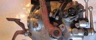
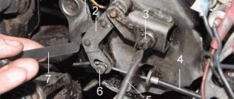
Place the gearbox on a clean table or workbench and begin disassembly. First of all, reset the kickstarter spring tension. To do this, on the front of the crankcase (where the box is attached to the engine), unscrew the two countersunk screws that secure bushing 1 of the kickstarter spring (photo 1). Then turn the box over with the back cover up (where the rubber cardan coupling is put on) and disconnect clutch lever 5 (photo 2), then remove slider 1 with a rubber ring (I advise you to give the slider to a turner to machine another groove for the second rubber ring, it’s more reliable) . Also remove the thrust bearing 2 and the tip of the clutch rod 3. Next, remove the wedge that holds the kickstarter 11 (photo 2) and remove the kickstarter itself.
Photo 2. Clutch release mechanism. 1 — slider with a rubber sealing ring, 2 — thrust bearing, 3 — tip of the clutch rod, 4 — clutch release rod, 5 — clutch lever.
Photo 3. Rubber coupling fork disc and castle nut.
Remove the cotter pin and unscrew the castle nut of the rubber coupling fork disk, then remove the fork disk itself (photo 3). Now you can use a 10 mm socket to unscrew all the M6 bolts securing the rear gearbox cover. Now, having inserted a metal pin into the hole in the clutch lever axis, lift the box slightly above the table, holding it by this pin, and with light blows of a wooden, plastic or lead mallet, knock out the primary and secondary shafts from the cover. The lid will remain in your hands.
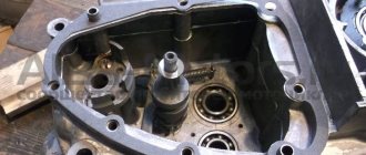
The time has come to wash everything from the inside using Solvent or gasoline and carefully examine all the insides of the gearbox, looking for wear or breakage of parts (photo 4). On the right is the secondary shaft 1, in the top center is the reverse idler gear 3, below it in the center is the primary shaft 4, to the left of it is shaft 5 on which the kickstarter ratchet gears rotate, and below on the left is shaft 6 of the lever with the kickstarter gear sector . Just below and to the right there is a gear shift mechanism 7, which is controlled using gear forks, which are installed on the shaft 8.
Photo 4. Location of shafts and gearbox parts. 1 - secondary shaft with first-fourth gears and reverse gears, 2 - reverse gear, 3 - reverse idler gear, 4 - input shaft with first-fourth gears and reverse gears, 5 - shaft with kickstarter ratchet gears, 6 - kickstarter shaft with a gear sector, 7 - gear shift mechanism, 8 - shaft with gear shift forks.
Subsequent disassembly of the box is simple and removing the shafts will not be difficult, but searching for worn parts will require attention and careful examination of the surfaces of the parts. When removing the shafts, I advise, in order not to confuse the parts, for each shaft with its gears, prepare some kind of container (bath), for example, cut out of a small oil canister. This will help you avoid mistakes and unnecessary movements later during assembly.
To begin, remove the reverse gear 3, and also remove the reverse gear 2 from the secondary shaft along with its shift fork. Remove the kickstarter shaft 6, together with its parts and the ratchet gears with thrust washers and spring 5. Remove the shaft 8 of the gear shift forks, and separate the shift forks themselves from the disc grooves. Next, put the fork disk of the rubber coupling in its place (on the secondary shaft 1) and secure it with a castle nut.
Then, with light blows of a mallet on the fork disk and on the end of the input shaft 4, remove both shafts from the gearbox housing along with the gear shift forks. Press out all the removable gears from the shafts, and also remove all the keys and bushings. When pressing, use pullers or a press, such as the one in this article. And between the press and the gears when pressing out, use spacers made of brass or bronze. The shaft details are shown in detail in photographs 5,6 and 7.
Photo 5. Details of the input shaft. 1,2,3- sealing rings, 4- bearing, 5,6- third and fourth gears, 7- input shaft with cut second, first and reverse gears, 8- key
When you remove the gear shift fork shaft from the gearbox housing, remove the pawl shaft, pawl and spring 3, then pull out the lever lock 1, and then remove the gear shift disk 2 from its axis (photo 8). To unscrew nut 4, remove the cotter pin that secures it, unscrew the nut and then remove the figured crank 3 (photo 9) from the splines of shift shaft 5. All gear shift parts are shown in detail in photo 9.
After disassembling all gearbox mechanisms, thoroughly wash all parts and carefully inspect them. Such noticeable defects as chipping or wear of gear teeth, breakage or wear of the surface (all parts should not have wear steps) of parts are immediately visible and should be replaced. The bearings should not have any play, crunch or jam, but in general I advise you to replace all the bearings with branded ones (read how to choose a bearing here), since recently the Ukrainian bearings that are used to equip the Dnieper boxes at the factory, and the Ural ones too, are of very low quality . The bearings should not rotate in the seat in the crankcase, but if this happens, then read this article for a way out. Replace all seals with new ones, preferably from European companies.
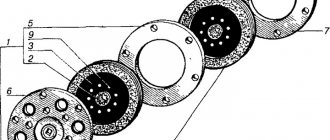
Photo 6. The secondary shaft is almost assembled. 1 - ball bearing, 2 - fourth gear, 3 - fourth and third gear shift clutch, 4 - third gear, 5 - second gear, 6 - second and first gear shift clutch, 7 - first gear, 8 - rear gear gears, 9 - washer, 10 - secondary shaft.
Also, most domestic gearboxes suffer from mismatched teeth of the shaft gears (primary and secondary), that is, the gears seem to be shifted relative to each other and their teeth do not work with the full surface, but only half. You can correct the position by moving the gear on the shaft and placing an adjusting washer.
All gears whose teeth are at least partially worn or chipped should be replaced with new ones. If the teeth are intact, but heavily worn, then the gearbox usually howls loudly, especially under load (when gas is supplied). Only new gears will help get rid of this. A puller will help you pull gears or bearings off the shaft, and I recommend looking at an example of a universal puller for most gearboxes here.
When purchasing new parts (gears), check their hardness using a needle file (otherwise there is a lot of raw lefty stuff on sale). The needle file should not leave marks on the gear teeth and surfaces of the new shafts. Backlash of shafts and gears is unacceptable. The keys on the shafts should not show wear in the form of a step, and the keys themselves should be inserted tightly into the keyway of the shaft.
Photo 7. Details of the secondary shaft. 1,4,5,8 - gears of the fourth, third, second and first gears of the secondary shaft, 2,6 - gear couplings of the secondary shaft, 3,7 - gear shift clutches, 9,11,12 - cast iron (cermet) bushings - bearings sliding of the first - third gears, 10 - secondary shaft, 13 - mounting keys of the secondary shaft (10) and gear couplings (2.6), 14 - reverse gear, 15 - input shaft assembly.
The shift forks may be worn at the point of friction, but wear in the form of a step is unacceptable. The same goes for the shift dial. Its pins should not have a development in the form of an oval or ledge (step). The pins of the forks that go along the figured cutouts of the disk should also not be worn out in the form of an oval or step. There should also be no stepped wear on the gearshift couplings or licked spline edges (on gear splines too), since this can cause the engaged gear to fly out, but small abrasions from friction are acceptable.
The gearbox housing and its cover must be connected to each other without distortions, and the planes of their joining must not have nicks, scratches or chips. Scratches and small nicks can be eliminated on a lapping plate, and chips can be restored by argon-arc welding, followed by grinding of the seams. Don't forget to install a new gasket under the box cover. It costs a penny, but it will help avoid oil leaks. I advise you to use a paronite gasket rather than a cardboard one.
Photo 8. Details of the gear shift mechanism. 1 - lever retainer, 2 - gear shift disc, 3 - shaft with pawl and spring, 4 - castle nut, 5 - gear shift shaft with crank cam and return spring.
The gearbox is assembled in the reverse order of disassembly. Before assembly, set the gear shift dial to neutral (put the gear in neutral between first and second). Also, do not forget to turn the kickstarter return spring 3 (in photo 1) 1.5 turns counterclockwise. To do this, you can use a grinder key by inserting it into the screw holes and turning the bushing with it. Then try to hold the bushing in this position, slightly lift one pin of the key, and insert at least one screw, and then the second.
After assembling the box, check that all gears shift easily and without jamming; when shifting, do not forget to rotate the secondary shaft by the rubber coupling. And in general, also check the ease of rotation of the shafts without jamming in all gears. Under the castle nut of the fork disk of the rubber coupling, or rather under the washer of this nut, do not forget to place a new rubber ring, and even lubricate it with sealant. This will prevent oil from flowing along the splines of the secondary shaft.
Photo 9. Gear shift mechanism. 1 - gear shift shaft with pedal, 2 - return spring, 3 - automatic clutch crank cam, 4 - washer, 5 - shaft with pawl, 6 - gear shift disc, 7 - castle nut, 8 - reverse gear fork, 9 - fork for shifting the first and second gears, 10 — fork for shifting the third and fourth gears, 11 — roller for shifting forks.
After repairing the gearbox and installing it on the motorcycle, the gearbox should be run in (especially when replacing most of the parts with new ones). To do this, place your bike on the center stand and start the engine, keep it in first gear for 10 minutes, at an engine speed of approximately 1500 rpm. Then let it run for 10 minutes in second gear at 2000 rpm, and then 5-7 minutes in third gear, and also in fourth, and this at 2000 rpm. Just remember to cool the engine with a household fan, or take breaks after each gear to cool the engine. After the first idle run-in, drain the oil from the box and fill it with fresh oil. All that remains is to run the motorcycle in again, but on the move, adhering to the above-described crankshaft revolutions and time for each gear, and not exceeding them.
When operating a motorcycle, often pay attention to the asphalt under the bike’s engine. If oil leaks appear, it is advisable to eliminate them in a timely manner and monitor the correct oil level in the crankcase. This is important, since most breakdowns or rapid wear of gearbox parts occur due to a decrease in oil level. By following this simple rule, your gearbox will not need repairs for a long time. Good luck everyone!
If this article is useful to you, please share it on social media. networks by clicking the buttons below. Thank you.
RќСЂР°РІРёС‚СЃСЏ