The assembly of the Izh-Planet 5 box is often carried out during its repair or replacement of parts. This unit is not highly reliable. This is due to the low quality of components, poor assembly, and poor requirements for the manufacturing accuracy of bearings, crankcases and other mechanisms. You can find your advantages too. Firstly, it is cheap to produce. Secondly, it can be repaired with your own hands. Let's look at what the part is and how to assemble the Izh-Planet 5 box, and also learn useful recommendations.
Most common problems
Most often, the motorcycle in question loses or shifts poorly in second gear. This may be due to careless turning on of speeds. For example, when picking up high speeds in first gear without neutral, when engaging the second speed gear, an impact occurs, which contributes to intensive wear of the unit. Therefore, it is not recommended to “spin” the first speed too much. If, nevertheless, problems with the second position continue, there are several options for resolving them.
In some cases, the simplest method will help, without completely disassembling and then reassembling the Izh-Planet 5 box. It is necessary to place the motorcycle on the right side, and then remove the kick starter and gear shift foot along with the shaft. Next, the crankcase cover and clutch basket along with the discs are dismantled.
When the gears of the box wear out, the meshing of the teeth deteriorates. In turn, this leads to slipping, jerking and failure of the second gear. Another reason could be wear on the input shaft bearings. Since it moves slightly to the left due to vibration, it is necessary to move it into place with light blows using a mallet. The installation of washers of suitable diameter will allow you to fix the element in the desired position. Then the bearing stopper and other dismantled parts are reassembled in the reverse order.
"Sores"
There are three problems in the planetary checkpoint:
- Oil leak from the intermediate shaft plug
- Poor gear engagement in first gear
- Constantly loosening the bolts securing the gearshift shaft stop
I solve the problem with oil leakage very easily and simply: I take out the retaining ring; I remove the intermediate shaft bearing, degrease the plug, retaining ring, mounting hole, then apply sealant to the outer edge of the plug, put it in place and immediately press it with the bearing and voila - the leak is eliminated!
Due to a factory defect, the gear-carriage for engaging the first-third gear does not fully engage the first-gear gear with its cams, but only in a small part, barely catching the gear with its cams, which is why the edges quickly wear out and the first gear begins to knock out.
This moment is clearly visible in the photo. For this particular gear, the hook was no more than a couple of millimeters. It is difficult to cure this “sore”: from the side of the first gear gear, you need to grind the end of the intermediate shaft by 3-4 mm and, using adjusting washers, move the first gear gear to the carriage. I don't see any other way.
During operation, the bolts securing the stop are constantly unscrewed, either due to vibration or something else - they are unscrewed and that’s it, no matter how you tighten them... Even special lock washers do not help. I struggled with this disgrace for a long time using all the traditional methods known to me and came to the conclusion that the best solution to this problem is red thread locker. Feel free to put bolts on it and get rid of this problem once and for all.
Other faults
It happens that disassembling/assembling the Izh-Planet 5 box may be necessary if the fourth speed disappears. This is often due to broken bearings on the output shaft. Such a nuisance occurs due to the presence of axial play, displacement of the bearing assembly, or its failure. You can try to fix the problem in the same way as repairing the second gear. If this does not help, you will need to completely disassemble the unit.
When the speed switch jams from a high range to a low mode, the spring system of the switching mechanism has failed. It needs to be replaced. Strained operation of the unit after assembling the Izh-Planet 5 gearbox indicates incorrect installation of the adjusting washers. To avoid this, it is necessary to mark and record the previous placement of these elements during the process.
Detection of faulty parts
To learn how to determine the damage and degree of wear of gearbox gears, consider the classification by which you can make the right decision about repairs. The gear needs to be replaced if:
- there is at least one broken tooth, or the presence of cracks in any part of the tooth caused by plastic deformation of the gear material.
- when the working surface of the gear is chipped by 20 percent or more, when the depth of chipping is 5 percent or more of the tooth thickness.
- if there is corrosion on the working surface of the gears;
- if the contact patch is less than 80 percent of the width of the teeth, and less than 60 percent of the height.
Disassembling and assembling the Izh-Planet 5 box
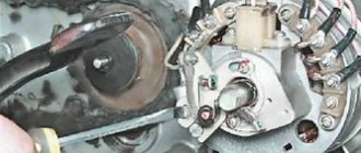
First, you will need to completely dismantle the clutch, starting device and motor transmission, and also drain the oil. After these manipulations have been carried out, you can begin to remove the gearbox. In the area of the right side of the motor, unscrew the eight mounting screws. The driver's footrests, foot brake lever, and crankcase cover on the right side are removed. The clutch cable is disconnected and the ball and pusher of the input shaft are removed. After this, the circuit is disconnected. Designations in the photo below: clutch discs (1,3), lower disc (2), inner drum (4), nuts (5, 6).
The crankcase cover is placed on the prepared rags or paper. You can pull it out by grabbing the star with your hands and pulling it towards you. If the element does not budge, look at the worm shaft support washer, which may have become warped. Place tweezers or a knife into the hole between the crankcase and the cover, and then straighten the part. When dismantling the housing, a couple of washers may fall out. The second element is slightly thicker and is mounted on the copy shaft. They must be signed and put away with the rest of the spare parts.
Removal and repair of Ural motorcycle gearbox
To remove the gearbox without unscrewing the motor, you need to do the following:
- Remove the rear wheel from the motorcycle.
- Remove the cardan drive.
- Remove 1 bolt and 3 nuts securing the gearbox to the engine.
- Then the gearbox can be pulled out of the motorcycle frame and you can begin to inspect it.
Repairing a Ural motorcycle gearbox involves replacing worn gears, followed by adjusting the gear shift mechanism. You should also pay attention to the seals - their wear will cause oil leakage, as a result of which the Ural motorcycle gearbox will operate in conditions of insufficient lubrication.
Main stage
As noted in the assembly diagram of the Izh-Planet 5 box, further disassembly operations are carried out above the insides of the roof of the unit, since the secondary shaft and sector could remain in it. If it is necessary to remove them, you need to straighten the petals of the lock washer, unscrew the nut, remove the star and washer. Holding the gear very carefully to prevent the shaft from jumping out, the cover is moved to a clean and flat surface with the gear facing up.
It is worth noting that the bearing of this part of the assembly does not have a retaining ring. Therefore, when removing the shaft with bearing, the rollers may fall out, so be careful. If the specified element has exhausted a decent service life, there is a risk that when dismantling the secondary shaft, the outer ring may jump out of the seat and remain on the rollers. Next you need to start pressing out the oil seal. To do this, the installation rings are removed from the hole in the cover, after which the outer ring of the bearing is removed.
Main problems and their solutions
Disassembling the IZ Jupiter 5 engine, the video of which is presented below, is carried out not only as problems arise, but also for preventive purposes. For example, cleaning the carburetor is one of the conditions for maintaining stable engine operation.
The IZ Jupiter 5 engine diagram is simple even for inexperienced motorists. Therefore, during repairs there will be no difficult issues. In most cases, breakdowns occur due to the negligence of owners who improperly operate the moped and do not perform regular maintenance. For example, incorrect selection of oil for a particular time of year. So, if any part wears out, it must be replaced.
Final stage
Next, the second and third speed gears are removed from the input shaft, after which the input shaft is dismantled. To do this, you will need to carefully knock it out using a stopper and a light hammer. The upper and lower forks are removed.
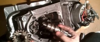
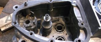
Next comes the intermediate shaft assembly. Using a screwdriver or other suitable tool, bend the clamp with the neutral indicator and carefully pull out the worm wheel. On its far side there are shims that could stick to the crankcase. They need to be collected and stored with the rest of the removed parts. Next is the turn of the copy shaft. Check the edges of the shaped sockets in which the guide forks move. They should not have chips or dents. We unscrew a couple of screws securing the switching mechanism, which is also removed. Now you can replace unusable parts and assemble the Izh-Planet 5 gearbox according to the scheme. The figure below shows: retaining cap (1), bolt (2), crankshaft sprocket (3), double-row chain (4), clutch drum (5), input shaft (6).
How does a Ural motorcycle gearbox work with reverse gear?
The two-shaft gearbox of the Ural motorcycle uses fewer gears when transmitting torque, which is the main reason for the increased efficiency. The input shaft of the gearbox has three initial speed gears, which are integral with the shaft. The purpose of the secondary shaft is to select the required gear, and the gears on it are not rigidly fixed. The gearbox of the Ural motorcycle with reverse speed has manual and foot shift methods, which makes it very convenient to use.
On later modifications of the gearbox, a removable rear cover appeared in the aluminum crankcase, allowing the gearbox to be repaired without removing it from the engine.
Among other motorcycles, it is precisely the ease of maintenance that distinguishes the Ural motorcycle - a major overhaul of the gearbox can be easily completed within a day, if the appropriate spare parts are available. It must be remembered that some parts from various modifications of the gearbox are interchangeable. This is one of the main advantages that makes it quite easy to assemble a working box from several faulty ones.
Repair
Once the unit has been gutted, you can begin to determine the parts that need to be replaced. As a rule, you have to buy a set of shims, a set of gaskets and sealant. This is the case if there are no more serious damage. Once you have decided on the elements to be replaced, you will need to adjust the worm shaft axis, and after final assembly, the clearance along the axis of the primary, intermediate and secondary shafts.
Adjusting washers are placed on the far ledge of the copy roller; they should be lubricated with a special compound. A support washer is mounted on the near edge, and the shaft is put in place. It should be turned so that the neutral sensor with its protrusion fits into the deepest groove. Then, using a ruler (without the gearbox cover yet) on the plane of the crankcase, measure the gap between the washer and the dipstick. It should be no more than 0.2 mm. Depending on the indicator, regulators are added or removed. If it is impossible to accurately set the gap, it is better to make it smaller.
Motorcycle Upgrades
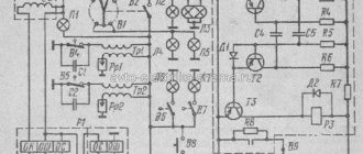
New electrical devices have appeared on the motorcycle:
- New generation alternating current generator with a power of 100 W;
- A new electronic unit consisting of a rectifier and voltage regulator BPV14-10;
- Electronic switch;
- Ignition coil IZH-PS;
- Modern instruments and warning lamps.
In addition, the power of lighting devices has increased, in comparison, for example, with the wiring diagram of IZH Planet 2:
- Headlights;
- Side lights;
- Direction indicators;
- Stop lights.
For reference: the combination of engine reliability and improved visibility has increased vehicle safety on public roads.
Assembling the box on the Izh-Planet 5 motorcycle
For proper assembly, you first need to install the input shaft, then the first gear gear with the groove down. Then the return spring is mounted with the range shift shaft; first, put on the spring mechanism and place the block in the seat. After this, a worm shaft with adjusting washers is installed. To make installation easier, lubricate the moving mechanisms with Lithol.
When installing the unit, care must be taken not to damage the neutral speed sensor. To get the shaft into place, use a screwdriver to bend this indicator slightly. When installing, remember the small washer, which eliminates play. A similar part is installed on the copy shaft. After this, the gear shift compartment is installed.
Engine Izh Jupiter.
Izh Jupiter 5 - engine, disassembly and repair.
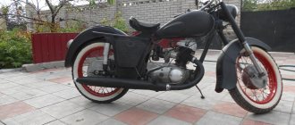
Despite the fact that Japanese motorcycles are increasingly conquering the Russian market, motorcycles Izh Jupiter 5 or Planet still remain popular, especially in the outback. Because they are cheap, unpretentious, easy to repair and maintain. But despite this, many novice motorcyclists cannot correctly disassemble the seemingly simplest two-stroke Izha engine, so as not to spoil anything. In this article we will look in detail at how and with what help to properly disassemble and repair the IZH-Jupiter-5 engine and not turn it into firewood.
The fact that it is time to disassemble the engine of your IZH for troubleshooting and repair will be indicated by increased noise (knock) when the engine is running, difficult starting, loss of traction (power) and compression measurements (compression less than 10-8 kg/cm²), confirming increased wear of parts CPG. If repairs are not started in time, then restoring a neglected engine will be much more difficult and expensive.
Well, I can’t say anything about the exact mileage after which the Izh’s engine will need to be repaired, since there are unique ones that can ruin the power unit in a couple of thousand km. And for a caring owner who carefully operates the motorcycle, regularly performs maintenance and pours high-quality oil into both the tank and the gearbox (and changes the oil on time), the engine mileage without major overhauls can exceed a rather impressive mark on the odometer.
After draining the oil from the engine crankcase and removing it from the motorcycle, I highly recommend washing it outside with a special engine cleaner, but if there is no such thing, then use a solvent, another solvent, or at least gasoline. Having washed the outside of the motor will guarantee that dirt will not get inside, and it will be much more pleasant to work with.
Having placed the clean engine on the workbench, prepare a tool kit consisting of sockets and open-end wrenches. But where possible, always use only spanners and sockets, this will prevent you from damaging the edges of fasteners tightened with a high torque.
In addition to wrenches and screwdrivers, for disassembly you will need some other tools, without which you will not be able to disassemble the motor without damaging anything. But these devices can be made with your own hands and I will tell you about them during the work.
IZ Jupiter - engine disassembly.
Before disassembling, I advise beginners to prepare a camera (or at least a mobile phone with a camera) and subsequently film all their actions and details. This will help you later put everything back together in reverse order, without memory lapses. Although I will publish some photos of the disassembly process and the most important parts in this article. So let's go.
First, you should remove the parts of the CPG (cylinder-piston group). To do this, use a socket head to unscrew all the cylinder stud nuts. Then you should remove the heads (the heads are easy to remove, unlike the cylinders) and carefully tap the cylinders in a circle with a plastic mallet, since in most cases the cylinders stick (glue) to the planes of the crankcase.
Having removed the cylinders from the crankcase and their gaskets (pulling them off the studs), before dismantling the pistons, just in case, mark them (which piston was in which cylinder). Perhaps further measurements will show (more on measurements a little later) that these pistons will still serve, or you will want to restore their size using the composition described in this article.
Having marked the pistons where each one was, remove the retaining rings from one side of each piston that hold the piston pin in place, then remove the pins from the pistons and remove the pistons from the connecting rods. On worn-out engines, the pins from the pistons are usually easily removed, but if they do not come out by hand, then in order not to bend the connecting rod, do not knock them out with an impact, but squeeze them out using the simplest device shown in photo 5 (I did it within an hour ).
Believe me, it’s better to spend time making a homemade device (by the way, one can now be found on sale) than to then struggle with straightening the connecting rod (straightening it very precisely is not so easy). And with a bent connecting rod, the new piston and rings will wear unevenly (on one side) in a matter of kilometers. In addition, this device will later be very useful when assembling your engine.
Having dealt with the piston group, you can then proceed to remove the generator. Removing its stator is quite simple by unscrewing the screws holding it. After unscrewing the screws, remove by hand the aluminum housing of the stator windings, together with the ignition system breaker (contact group).
But to remove the armature (generator rotor), you must first unscrew the long screw that holds the armature to the crankshaft cone. And this screw has a rather rare M7 thread and is well tightened, so in order not to spoil the edges of this screw, use only a cap socket.
Having unscrewed the screw, you should then compress the armature from the crankshaft cone. To do this, you should use a screw puller, which is shown in the drawing on the left and which you will have to order from a turner. But you can also use a long bolt with an M10x1.5 thread, only the bolt will have to grind off the thread on its end to a diameter of 8 mm (as in the drawing).
Next, remove the clutch release rod from the sprocket shaft. To do this, we tilt the engine on its side, and after the rod has fallen out, we take a steel ball and another rod into our hands.
Now we leave the crankcase lying on its side and then use a screwdriver to unscrew the 4 screws holding the crankcase hatch 1 (see photo on the left) and remove this hatch. Through it we drain the remaining oil from the crankcase cavity.
Now you can turn the crankshaft a little by hand until the faceted head 2 of the flywheel bolt appears in the hatch window. You should loosen this bolt two or three turns with a 19 socket head so that you can then separate the crankshafts when the crankcase is halved.
By the way, you can halve the engine without even removing the cylinders (more about this in the video below the article).
Next, remove the chain casing 1 from the crankcase (see photo on the left), behind which is hidden one of the screws holding the crankcase halves of the Izh Jupiter engine together. Then you should use a suitable drift to knock out the guide bushing located in the front crankcase boss (see photo on the left - indicated by a yellow arrow).
By knocking out the bushing indicated by the yellow arrow in the photo, you will subsequently make it much easier for you to “halve” the crankcase into two parts. If the bushing is too tight, do not apply strong blows, but rather heat the crankcase boss with a technical hair dryer. And because the heated crankcase expands slightly (more precisely, the hole for the bushing expands), the bushing will come out much easier.
You can then remove the shift lever (by loosening its bolt) and the kickstarter lever. Having removed the levers, unscrew the screws of the left engine cover, remove it and unscrew the nuts 5 of the clutch pressure plate (see photo on the left). After unscrewing all the nuts, try not to lose the caps and springs of the clutch mechanism.
Using thin screwdrivers, pry the disk pack through the slotted holes of the clutch drive drum and remove them from the drum - the whole pack is in your hands. Set it aside for now, along with the caps, their springs and nuts.
Next, you need to unscrew the nut (left-hand thread) from the driven shaft of the motor transmission (the nut that was under the discs in the clutch basket. In this case, use a union head and unscrew the nut after inserting a special stopper between the teeth of the sprocket (reverse gear) and the engine crankcase or at least a soft alloy rod.The gearbox must be in some gear.
Now you need to unscrew the bolt holding the drive (small) sprocket of the motor chain to the crankshaft. In this case, first remove the locking cap of the 2 sprocket bolts with a screwdriver (see photo above). Then, before unscrewing the sprocket bolt, you should block the crankshaft from turning using a rod or pin inserted into the upper head of the connecting rod (a soft alloy rod).
We place a wooden block under the rod inserted into the connecting rod (preferably two on each side) and begin to unscrew the sprocket bolt. The bolt itself not only fixes the sprocket on the crankshaft, but also plays the role of a sprocket remover when unscrewing it.
That is, we rotate the bolt until the sprocket slides off the crankshaft shank. Don't lose the sprocket key, but ideally it should fit fairly tightly in the crankshaft groove and not fall out of its groove. If the key is loose (this often happens from the factory), then, of course, you should make a thicker key (preferably from 45 steel) and press it into the groove during assembly.
Also, you should not lose washers, which can be placed under some kind of sprocket so that they work in one line, without distorting the motor chain. After removing both sprockets with the motor chain, set them aside and cover them with a clean rag to remove dust. If the motor chain sags too much, it is advisable to replace it with a new one during assembly.
Next, remove the kickstarter return spring, and to unwind it, the kickstarter itself, put back on its splined shaft, will help. Now you need to unscrew all the screws around the perimeter of the crankcase that hold its halves together.
I advise you to unscrew those screws that cannot be removed with a regular screwdriver using an impact screwdriver. But the blows are not too strong, because the crankcase is cast from a rather fragile light alloy. Having unscrewed the screws around the perimeter, carefully check that they are all unscrewed, and only after that you can try tapping the crankcase with a plastic mallet and try to separate the crankcase halves.
An important point: do not try to drive screwdrivers, various wedges, chisels and other similar objects between the crankcase halves. By doing this, you will spoil the smooth mating surfaces of the crankcase planes and subsequently the two-stroke engine will not work normally due to loss of tightness, and in this case oil leaks are guaranteed.
When separating the crankcase halves, it should be noted that they are now held in place by the outer races of the bearings in the seats in the covers (if all the guide bushings in the bosses have been removed), so tap the covers with a mallet in the area of the shafts and their bearings.
In this case, turn the crankcase sideways, and trust an assistant to hold the crankcase by one of the halves, while tapping the lower half of the crankcase (and in the area of the bearings) from the sides along the perimeter. At the moment of tapping, the lower half of the crankcase, under the force of gravity, will separate from the upper.
It is also useful to insert a thin rod made of a soft alloy (preferably lead) into the holes in the crankcase bosses (for guide bushings) and, resting it against the edge of the hole in the lower half, apply gentle blows to the rod (punch). We do the same in the hole on the opposite side, alternately delivering gentle blows. In this case, an assistant holds the crankcase by the upper half.
When separating the crankcase halves, act carefully and without jerking, since if you do not act carefully and sharply, you can scatter the set of gears of the Izh Jupiter engine gearbox. Separate the crankcase halves by slightly lifting the crankcase above the table.
If, while operating the motorcycle, you notice that something is wrong with the gearbox and there is a need to remove the gearbox mechanism (worm, intermediate and input shafts), then you should mark the location and number of adjusting washers on the shafts (it wouldn’t hurt to photograph everything from all sides).
All shims and their location may not seem like such important details to beginners. But if you do not install one of the washers in its place during assembly (or swap washers of different thicknesses), then you are guaranteed to have unclear operation of the box, or even failure of the gearbox mechanism. Therefore, take all details, even small ones, very seriously, if you don’t want to re-halve the engine at the height of the season and, after opening it, organize a competition of what, where, when?
Having marked and disassembled all the gearbox parts, put them in a clean box (for example, cut from half a canister) for further troubleshooting of the parts (which will be described below). Now you can begin the final cycle of disassembling the Izh Jupiter engine.
We remove the keys from the shafts, then unscrew the screws of the 5 crank covers (see photo on the left) and then remove the covers and take out the crankshafts.
It should be noted that the covers seem to be the same, but they are not interchangeable and therefore be sure to mark them as to which one was which.
When dismantling crankshafts, you should use a special key (as in the photo on the left), which acts as a puller. For those who do not have such a key, it is not difficult to make a puller from sheet metal (about 8 - 10 mm thick) by cutting out a plate and drilling holes in it, according to the drawing just below.
Having completely disassembled the motor and laid out all the parts, you can begin to troubleshoot them in order to understand who was responsible for the poor performance of the motor.
Troubleshooting (diagnosis) of Izh Jupiter engine parts.
Having disassembled and halved the engine, you now have the main task - to examine its entire interior and all the parts in order to understand what to do next. Let's probably start with diagnosing the piston group.
Cylinder-piston group. In general, an indicator bore gauge and a micrometer will help to accurately judge wear. We measure the diameters of the pistons with a micrometer and record the readings. And the cylinder should be measured with an indicator bore gauge in three zones to identify the wear of the barrel-shaped cylinder, and also measure the cylinder crosswise to identify the wear of the oval-shaped cylinder. I recommend reading in detail about cylinder measurements in this article. We read in detail how to use a caliper here.
I also recommend reading this article about measuring and replacing the piston, cylinder and piston pin of motorcycles, it describes some useful subtleties.
But for those who do not have the above-mentioned measuring instruments, but only have a set of feeler gauges, the amount of wear can be determined by inserting a suitable feeler gauge between the piston and cylinder (in the middle of the cylinder) and identifying the gap in the mating parts (piston and cylinder).
If the gap between the piston and cylinder is more than 0.4 mm, then you should buy new pistons from the next repair group and bore the worn cylinders for these pistons. Boring and subsequent honing will allow you to get rid of the barrel and oval-shaped wear and return the cylinders to the correct geometry. I recommend reading more about cylinder repair and homemade hone here.
Piston pins and bushings. Next, check to see if new repair pins are needed. To do this, insert the old fingers into the upper heads of the connecting rods and if the fingers dangle in the bushings (with a gap of more than 0.01 - 0.03 mm), then you should buy thicker repair fingers.
If the new fingers do not fit into the bushings of the upper heads of the connecting rods, then you should unroll the bushings using a suitable reamer and ensure that the diameter of the bushings becomes such that the new fingers are inserted into the bushings with a gap of 0.01 - 0.03 mm. By the way, it’s better to buy thicker fingers and unscrew the bushings using a reamer anyway, since the bushings also wear unevenly and have an oval shape.
But I highly recommend unrolling the Izhevsk engine bushings using a reamer as described in this article, otherwise the service life of the new pistons will not be long and they will wear out unevenly. There I also wrote why the engine of the Izh Jupiter 5 and other Jupiter models, after repairs, begin to ring with a vengeance.
Piston rings. Well, checking the piston rings is quite simple - insert them just above the middle of the cylinder (insert by pushing the rings with the piston) and look at the gap in the ring lock.
If the gap is more than 1 mm (visible even without measuring probes), then you should buy new rings. I wrote more about replacing piston rings on a motorcycle engine in this article.
Crankshaft. Now let's check the crankshafts. We take the connecting rod with our hands and sharply shake both cranks in turn. If you feel a click when you shake it sharply, it means that the needle bearing of the lower head of the connecting rod has increased clearance (wear) and I advise you to replace such a crankshaft with a new one.
Or restore the crank using repairs, for example as described here. And although I described there the restoration of the crankshaft of heavy motorcycles, the principle of operation for Izhevsk crankshafts is almost the same. And most importantly, it describes how to correctly connect the crankshaft parts.
Generator. Next, you can diagnose the power plant of your engine. In general, IZH generators are practically indestructible, but still a careful inspection will not hurt. Inspect the brushes - they should move freely in the rectangular holes of the brush holder (when you press any of the brushes with your finger, they should easily return back).
The brushes should protrude from the brush holder by at least 5 mm (replace worn ones) and clean all terminals and parts of the breaker (especially the contact group).
Blow the stator and generator armature from brush wear products (coal dust), and I advise you to polish the contact rings for the brushes (on the armature) with 1500-2000 grit sandpaper to remove dark deposits. If there are marks or scratches on the slip rings, then first use sandpaper with a coarser abrasive (800 - 1000), and at the end polish it with the finest one. After sanding and polishing, wipe the rings with alcohol.
Clutch and motor transmission. Inspect all the teeth of the sprockets and if they are worn out or chipped, then we reject such parts and look for new ones. The same applies to a sagging (stretched) motor chain. Carefully inspect the splines of the clutch drum and if they are heavily worn, the drum will have to be replaced.
If the hole is small, use a file to smooth out all the burrs (steps) on the drum splines, since if they are not leveled, the disks will move in the splines (slots) with jamming.
Next, inspect all clutch discs. If the plastic friction material of the drive discs is worn down to the ground (the round protrusions are worn out), or the metal driven discs are warped from overheating (we check the curvature by placing the disc on the glass), then replace such parts with new ones without hesitation.
By the way, the wear of the clutch discs could be determined in advance, when your motorcycle moved sluggishly (with the clutch slipping) and no clutch adjustments helped. And as usual, disassembly and inspection of clutch parts confirms the defect.
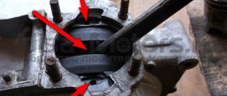
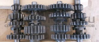
Izh Jupiter gearbox. Wash in kerosene, solvent, or diesel fuel and carefully inspect all the gears, especially their protrusions (sectors), indicated by the red arrow in the photo below.
These protrusions should not be licked or have step-shaped wear, as shown on gear number 1. But they should have sharp edges (or almost sharp - a small chamfer is acceptable), as shown on gear number 2.
Gears with worn teeth will howl, and trips with worn sectors are fraught with gears jumping out while driving. Therefore, replace worn parts with new ones without hesitation, especially gears with chipped teeth.
Also carefully inspect the gearshift forks, which should not have a step-shaped development on them (the stepped development on the fork is shown by a red arrow in the place under the number 3 in the photo on the left). Scuffs on the fork are a common occurrence and are quite acceptable, but if wear is visible in the form of a step, then such a fork will have to be replaced with a new one.
If there is no play on the secondary shaft of the gearbox, then I do not advise beginners to disassemble it unnecessarily, since assembling the roller bearing of this shaft requires experience and skill.
Well, such parts as the kickstarter shaft, its ring gear and the spring practically do not wear out, but the clutch ratchet can become loose and if this happens, you should tap its rivets (indicated in the photo on the left with a yellow arrow) until the play disappears.
Inspect, feel and check all bearings, and if there is noticeable play in the outer race relative to the inner race, then such a bearing should be replaced with a new one. I advise you to read how to choose a bearing here.
In conclusion of this section, regarding the diagnosis of Izh Jupiter engine parts, I would like to say that any wear on the parts is clearly visible even to the naked eye. And whether to leave parts with wear or increased play or not, everyone decides for themselves.
But you should always remember that both wear and play of parts are a source of increased noise when the engine is running, and in the gearbox they can cause not only noise, but also unclear operation of the gear shift mechanism. Therefore, it is still better to spend money once and replace all worn parts (including oil seals), but you can forget about repairs for a long time.
Izh Jupiter engine assembly.
We assemble the engine in the reverse order, and if the beginners took photographs during disassembly, they will help assemble everything much faster. I advise you to inspect the connector planes of the crankcase halves before assembly, and if some “Kulibin” half-shaved the engine before you, using a screwdriver or wedge, then there are probably nicks on the contact planes of the crankcase halves.
Such halves should be ground in on the stove, and everything will have to be assembled using bakelite varnish or high-quality sealant. I just advise you to read the instructions for the sealant, is it capable of hardening without air access?
During assembly, when you insert the crankshaft journals (shaft ends) into the new oil seals, use the thin-walled mandrel shown in the figure on the left. If there is nowhere to order such a mandrel from a turner, then use instead at least a piece of plastic cut from a plastic bottle and rolled into a roll. This device will not allow the thin edges of the new oil seals to be damaged.
The crank chamber covers can be pressed in using gentle blows with a plastic mallet (tapping in a circle and closer to the center, not along the edges). Assemble the gearbox parts with fourth gear engaged.
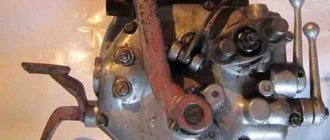
Connect the worm shaft itself to the ring gear according to the marks in the form of red dots shown with yellow arrows in the photo just below (I advise you to put the marks before disassembly, if they were not there from the factory).
And the first gear gear (shown in the photo on the left with a yellow arrow) should be put on the shaft at the same time as the left half of the crankcase.
When assembling the motor chain drive, after tightening the drive (small) sprocket nut, be sure to tighten the nut cap. Next, assemble the clutch discs, and if you did not mark the old discs, or replaced them with new ones, then place the steel disc with the ring groove first (first in relation to the gearbox), chamfer down.
When assembling, install the crankshaft flywheel in the middle of the parting line of the crankcase halves, and tighten its collet nut using a torque wrench, with a torque in the range of 17 - 20 kg.m. Pour 100 grams of engine oil into the crankcase cavity, and pour 1 liter into the gearbox crankcase cavity. For summer, SAE 40-50 is preferable, and if you travel with a stroller in winter, it would be advisable to replace it with SAE 30. Well, or immediately fill it with a high-quality all-season compound.
Device for pressing in piston pin. 3 - piston, 4 - piston pin, 5 - guide sleeve, 6 - connecting rod, 7 - screw.
Assembling a piston group with bored cylinders and new pistons, I think, will not be a problem even for beginners, but I advise you to press the pins into the pistons not by impact (bending the connecting rod), but using the device shown in the photo on the left.
After assembling the motor, check the tightness of all fasteners again, with the torque shown in the table on the left (depending on the thread diameter) and after that all that remains is to mount the repaired motor on the motorcycle.
We carry out the running-in as recommended by the manufacturer for a new engine. That seems to be all. I hope this article on rebuilding the Izh Jupiter engine will be useful to beginners and they will be able to rebuild the engine themselves, good luck to everyone.
If this article is useful to you, please share it on social media. networks by clicking the buttons below. Thank you.
RќСЂР°РІРёС‚СЃСЏ
Important
When performing these operations, follow the mark in the middle part of the sector. It should coincide with a similar mark on the shaft. The last step is to install the crankcase cover. If the work is carried out correctly, it will sit in its place without problems.
It is necessary to ensure that all rods and shafts coincide with their original mounting sockets. They should rotate freely without creaking or jamming. Use moderate force when tightening the screws as the threads in a soft metal crankcase can easily be stripped. All fasteners are tightened evenly to avoid distortion.
Preparation
To perform a high-quality repair, the engine parts must be clean, the threads in the crankcase must be threaded, the seals and gaskets must be new.
First, we clean the oil channels in the crank chambers. There are two channels in the Izh-Planet engine: one in the left half of the crankcase, the other in the right. We find the channels and if they are very clogged, we clean them with wire, rinse them with clean gasoline and blow them with compressed air.
Large selection of spare parts for IZH motorcycles
In this section we have collected a wide range of spare parts for the IZH Planet motorcycle. The proposed list of parts will be indispensable for those who want to return to operation an inherited unit, or plan to buy a used retro motorcycle for further restoration. These components have the following advantages:
Since the “Planet” has a simple and reliable design, most motorcyclists repair the “iron horse” themselves. Fortunately, this motorcycle responds to care. Despite its age, the IZH “Planet” remains a fully functional vehicle.