Modern scooters made in China have a similar layout. The engineers of the Celestial Empire did not bother and assembled all the critical components according to a single scheme. Even if there are differences, they are minimal.
This statement is also true for the electrical components of the moped. Any owner periodically encounters problems associated with these nodes. The electrical circuit of a Chinese 4t scooter is not a complex system; it contains only the main elements necessary for the full operation of the unit.
Knowing the main electrical wiring components and their purpose, you can quickly find the problem and fix it.
Delta moped wiring diagram china
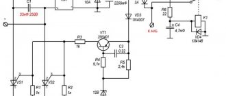
The electrical circuit diagram of Chinese scooters is shown in the figure:
As with other electrical connections, there is a common wire on all cube mopeds. In this diagram it is the negative tire running along the entire body. The corresponding battery terminal is also connected to the scooter's frame, ensuring that each electrical component's ground is in constant contact with the power source.
Electrics and electrical equipment of a scooter
The main components in the 4t moped circuit are:
- central locking;
- battery charging source – generator;
- voltage limiter;
- spark formation and control systems;
- control elements for headlights, brake lights, turns;
- fuel level indicator in the tank.
All circuits are connected together using wiring.
Depending on the modifications and dimensions of the scooter, the instrument panel may include a tachometer - a device for monitoring the number of engine revolutions.
All of the listed nodes of the general scheme perform a strictly assigned role. Failure of at least one of them leads to the cessation of operation of the connected devices. Therefore, monitoring the serviceability of the main elements must be done every certain period for the purpose of prevention.
Photo report: How to check a scooter's generator?
Just like that, without minimal knowledge of electronics, at least at the school curriculum level (like mine) and a simple multimeter tester, you won’t be able to test the generator, don’t even dream about it. Before taking on such work, you should at least be able to use a tester and understand that current can be alternating or constant, know what an electrical impulse is and what resistance is. Do you know all this? Have you held a tester in your hands? If yes, then let's not hesitate.
Checking the functionality of the generator should begin with measuring the voltage that the generator itself must generate and transmit through wires to consumers. We look at where the wiring harness from the generator comes out of the engine - we move along it until we reach the connector with which the generator is connected to the on-board network of the scooter.
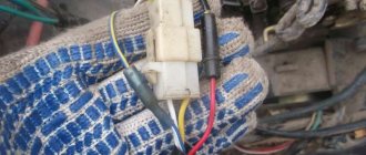
On the vast majority of scooters, the alternator connector looks something like the picture. In the common connector, there is one plug and two wires that are connected to the scooter’s on-board network through round terminals.
The plug combines the connectors of the two main windings of the generator: The working winding (yellow wire), which ensures the operation of the headlights, turn signals, lights and other consumers. And the control winding (white wire), the control winding provides voltage control in the main winding of the generator. That is, when the voltage in the operating winding of the generator increases above the specified limits, the relay-voltage regulator supplies current to the control winding of the generator, due to which the voltage in the operating winding of the generator drops to the specified limit. When the voltage drops, the reverse process occurs.
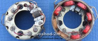
In this generator, the main windings are wound with thick copper wire on six coils.
The third winding of the generator, which is usually called high-voltage or inductive, and the magnetic induction sensor of the generator are connected to the scooter’s on-board network through round terminals.
High-voltage winding of the generator - ensures the generation of high alternating voltage (the voltage in this winding can reach 160 V or more), which directly enters the switch where it is rectified, then accumulated in the capacitor and at a certain moment in the form of a pulse is supplied to the ignition coil.
In this generator, the high-voltage winding is wound with a thin copper wire on two coils. The high-voltage winding coils are carefully insulated on the outside.
There are generators in which the high-voltage winding is wound on only one coil.
A small clarification: ignition systems in which a DC CDI type switch is installed, the high-voltage winding does not participate in the formation of a spark charge on the spark plug, so there is no point in checking it. Scooter manufacturers install a generator with a high-voltage winding, but do not use it (meaning ignition systems with a DC CDI switch). It's just wound on the generator and that's it. I will say more: due to the fact that the winding is not loaded with anything during operation of the generator, over time it simply burns out.
An example of a generator, on two coils of which a high-voltage winding that is not involved in operation is wound. I checked this winding - the tester showed an open circuit, which confirms the above.
The resistance of the generator's inducing winding is always greater than that of the other windings. The wire coming from the inducing winding of the generator is almost always red and black.
The magnetic induction sensor, when a special ledge on the generator rotor passes past it, generates an alternating pulse that opens a theristor through which the switch capacitor is discharged to the ignition coil.
Sensor in person
Ledge on the generator rotor
The wire coming from the magnetic induction sensor is almost always blue-white.
A small educational program: Traders and collective farm tusks, magnetic induction sensor of the generator, CDI ignition systems - called the Hall sensor. My dears... Maybe that's enough already?.. Where does this illiteracy come from?.. The magnetic induction sensor of the generator, the CDI ignition system, and it is this system that is discussed in this article - it has nothing to do with the hall sensor! And don’t listen to these hucksters and “gurus” who say the opposite...
The actual check itself
We switch the tester to the alternating current (ACV) measurement mode to a range of 200 V and no less. We remember that the voltage of the inducing winding can reach 160 V or more, so the measurement range of the voltage of the inducing winding must be at least 200 V.
We disconnect the plug and round terminals of the main harness - connect one probe of the tester to ground, connect the other to the terminal (black-red wire) of the inducing winding of the generator. Turn on the ignition and turn the engine with the starter. A fully operational pickup winding should produce approximately the following values.
The pulse generated by the sensor is very weak, therefore, we switch the tester to the alternating voltage (ACV) measurement mode in the 2 V range. Measuring the pulse from the sensor in a higher range may not give a result, since the tester may simply not catch it. For this purpose, use only a tester with a range in AC voltage measurement mode of no more than 2 V.
We do everything exactly the same as in the first example. The pulse from the sensor should produce approximately the following values.
By analogy with the first two examples, we measure the voltage in the working and control windings. We put the tester in the alternating voltage (ACV) measurement mode in the 200 V range and take measurements.
Well, what did you measure?.. Do all windings generate current? Or not all?.. If any winding does not produce current, then whether you like it or not, you will have to remove the generator and check it in more detail. But if the windings generate a current of approximately the same magnitude as in the pictures, then this means that your generator is in perfect order. Something like this…
In-Depth Check
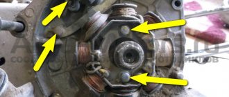
We lay the generator so that the terminals of the generator windings are accessible to you. We determine the ends of the terminals of all generator windings. Finding the ends of the windings is very simple: look at the color of the wire that is soldered to the terminal block and determine what kind of winding it is.
I have marked the ends of the windings here with arrows. I selected the arrows in color in accordance with the color of the wires soldered to the terminal block. The green arrow marks the terminal block on which the ends of all windings are soldered - this is the ground terminal block.
We switch the tester to the dialing mode, take any wire from the common harness, connect any tester probe to this wire, and with the second probe touch the terminal block to which this wire is soldered. The tester should beep and show zero resistance.
If the tester is “silent” and shows numbers instead of zeros, then this means that there is a wire break somewhere or poor contact between the end terminal and the wire. Inspect the wire carefully for a break and, if necessary, replace it with a new one. We check the remaining wires, including the sensor wire, using exactly the same principle.
After checking the wires, we proceed to checking the generator windings for open circuits and interturn short circuits. We switch the tester to the continuity mode, touch any tester probe to the generator housing, and touch the end of the wire of any winding or terminal block with the second probe.
The high-voltage winding in the continuity mode should show approximately this resistance value. If the high-voltage winding does not show resistance or shows little resistance, then this means that somewhere there is an internal break or an interturn short circuit. You understand that such a malfunction cannot be “treated.”
When checking the remaining windings, the tester should emit a sound signal; the resistance of the working windings is very small, so most likely you will only see zeros on the tester display. If the tester does not emit a signal, it means there is an internal break somewhere. Such a malfunction cannot be “treated.”
We put the tester in dialing mode, touch the sensor body with any probe, touch the sensor wire or the terminal on the body to which the wire is soldered with the second probe. The resistance of the sensor winding should be approximately within these limits. If there is little or no resistance, replace the sensor with a new one.
Egnition lock
This component in the circuit of a 4-stroke 50cc or 150cc moped represents a switch. Moreover, it is multi-positional.
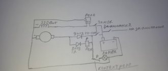
The lock performs the task of a central switch. It turns off the power to the entire scooter and turns the circuit back on when you turn the key. The larva itself is connected to a slider, which closes the corresponding contacts.
In the first position, the main wires interact - red and black. Current from the battery is supplied to the main circuits of the scooter. Since then it has been ready to launch.
The remaining positions close the black and white wire from the ignition module to the ground of the scooter. The operation of the motor is blocked by interrupting the spark supply from the coil. Depending on the modification, some models have a stop button in the electrical circuit. It performs the same function as the lock.
Design and principle of operation of a scooter generator
To the average person who is not experienced in electrical matters, a scooter generator may seem like a very complicated device. This is partly true: electric current is an invisible thing to the eye, and if we can see or touch mechanical faults, then we can only guess about faults in the electrics of a scooter or identify them using special measuring devices.
However, “it’s not the Gods who burn the pots” and if a person has a desire for something, then this article will be a good help, but for those who don’t want anything, there’s no point in continuing.
The scooter generator is a flywheel type generator with permanent magnet excitation. This type of generator is used on the vast majority of scooters, as well as mopeds and small motorcycles.
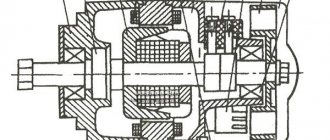
Designation of the main elements of the generator
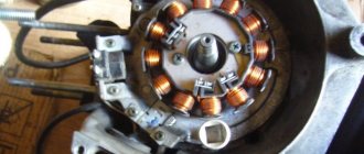
The scooter generator consists of a rotor (in collective farm language - “anchor”) and a stator. The rotor is mounted directly on the crankshaft and while the engine is running, the rotor rotates around the stator coils
The stator is attached directly to the engine crankcase. And while the engine is running it remains motionless. The stator is a metal base made of several plates of special transformer iron. On the base of the stator there are special projections (coils) on top of which a copper wire is wound in a strictly defined order - forming the generator windings.
Depending on the generator model, there may be two or three windings. The generator shown below has three windings: supply, control and high-voltage
Permanent magnets are installed on the inner surface of the rotor. Magnets have different polarities. The magnets in the drain are covered with a lid; if you remove it, you can see them
Each magnet forms a static (constant) magnetic field around itself. In turn, the field of each magnet will be different: blue is negative (“north”), red is positive (“south”)
If we insert the stator into the rotor in the same way as is done on the engine, then we will see that the stator coils will be in the magnetic field of the magnets located next to them.
After we start the engine, the rotor magnets will begin to rotate around the stator coils. During the rotation of the rotor, magnets of different polarities will approach the coils, which always stand still, and the field in which the coils are located will change at a very high speed. Due to the rapid change of magnetic fields, magnetic induction will occur in the generator coils and the generator will begin to generate electric current.
Current is good. But the current of a generator with excitation from permanent magnets is not a constant value and directly depends on the engine speed: the higher the engine speed, the more often the field of the coils changes - the induction increases and, as a result, the voltage in the coils increases. So it turns out that at idle engine speed the generator voltage will be 8-10V, and at maximum 60-70V.
In order to stabilize the generator voltage to specified limits, a special generator voltage regulating module was introduced into the scooter’s power supply system. That’s what it’s called: generator relay-regulator.
The principle of operation of the relay regulator is very simple: there are three windings on the generator stator: supply, high-voltage and control. The power winding is the main one and is designed to power the lights, sound signal and charge the battery.
The control winding is auxiliary and if the voltage in the supply winding increases, the relay-regulator supplies voltage to the control winding - the induction is disrupted and, as a result, the voltage in the supply winding of the generator drops.
When the voltage decreases, the opposite happens: the relay-regulator stops supplying current to the control winding, induction is restored, and the voltage in the supply winding increases.
The control and auxiliary windings of the generator are wound on the same coils.
The high voltage winding is wound on individual coils or coil. The high-voltage coil is needed to form a spark on the spark plug and is only partially related to the generator. Rather, it relates to the ignition system, which is a separate module and has little to do with the operation of the generator.
Another auxiliary module of the generator is a load resistor. It is needed to ensure that the generator does not operate without load. For devices that generate current, working without a load is like death. The designers foresaw this possibility in advance and, in order to prevent the generator from running idle, they slightly loaded the supply winding onto the resistor.
In addition to the elements described above, the scooter’s energy supply system includes an ignition sensor, which, at the right moment, ensures the formation of a spark at the spark plug.
This module is the same generator only in miniature and it works exactly on the same principle
On the outside of the rotor there is a small magnet in the form of a rectangular protrusion. This magnet, just like its larger brothers, forms a constant magnetic field around itself, and what happens next, you probably already guessed: while the engine is running, the field passes through the sensor coil and a small current is generated in it, which goes directly to the switch, controlling the torque in it sparking.
Original article...
Generator
Owners of 50cc who are familiar with the design of the scooter will immediately understand the purpose of this device. It produces an alternating electric current that powers the moped when the engine is running. But the second main task is to charge the battery while working. That is, the battery ensures the operation of the devices when the engine is turned off, and then the generator takes on this task.
The connection is made according to the following principle. There are several wires coming from the generator. The negative tire is attached to the frame of the scooter. There is alternating voltage on the white wire, which is immediately sent for rectification and stabilization.
In the electrical circuit, the yellow wire powers the low and high beam lights. Additionally, a Hall sensor is located in the generator housing. Its task is to generate impulses to control sparking. It is not electrically connected to the generator; it is connected to a white-green and red-black wire. The sensor is connected to the CDI block.
Scooter generator. Operating principle and diagnostics
The scooter's generator is a key component of the entire electrical system of the scooter, because it is it that generates the electricity necessary for its operation. Modern scooters are equipped with many different devices and components that consume electricity. Thus, the scooter’s generator ensures the operation of the headlights, ignition system, dimensions, etc. In addition, the scooter's generator also charges the battery, which in turn powers the electric starter when starting the engine.
The principle of operation of a scooter generator is extremely simple; at its core, it is the most ordinary Magdino with a flywheel. Magdino (magneto plus dynamo machine) differs from a simple magneto in that it has two windings installed on it, which differ in voltage, while a magneto has only one winding installed. Installing two windings instead of one significantly reduces the load on the system and thereby increases its reliability and service life. So the high-voltage winding generates electricity, which is used to operate the scooter’s ignition system, while the low-voltage winding, which is also often called an inductance coil or a “light” coil, ensures the operation of headlights, dimensions, battery charging, etc. The voltage of the coil depends on the number of turns in the winding; the more turns, the higher the voltage.
The generation of electricity itself occurs due to electromagnetic induction. The crankshaft rotates a flywheel with permanent magnets around the coils, as a result of which the magnetic field inside the windings changes all the time and thus the required voltage is inducted. Interestingly, since the scooter's generator is a magdino, the magnetic armatures around the ignition winding and the light winding can even rotate at different speeds. Around the ignition coil directly on the crankshaft, and around the light coil through a special gear “raise”.
As you might have guessed, a scooter's generator can only produce alternating current. While many devices require direct current to operate. In particular, the battery can only be charged from constant voltage.
In short, direct current is a simple directional flow of electrons that moves from one pole to the other, while in alternating current the electrons constantly change direction. In order to convert alternating current into direct current, special diode rectifiers are used on the scooter. Roughly speaking, a diode allows electrons to flow in only one direction, thus converting alternating current into direct current. Thanks to diode rectifiers, a scooter generator can power any device, regardless of what type of current the device needs.
Since the voltage supplied by the scooter generator varies depending on the crankshaft speed, for the normal operation of all devices and components of the scooter, a voltage regulator is needed. As a rule, this unit is combined with a diode rectifier. But on older scooters and mopeds, a separate relay may be used as a voltage regulator. Typically, a scooter's generator produces excess voltage, both at low and high speeds, which must be “cut off”, otherwise all the electrical appliances on the scooter can very easily burn out. The scooter's generator produces voltage, as if with a reserve, so that it is definitely enough for the normal functioning of the entire electrical system of the scooter. However, it should be understood that when installing some new equipment on a scooter or, for example, replacing a standard headlight with a more powerful one, the voltage generated by the scooter's generator may not be sufficient for the normal operation of the new device. In this case, you should either refuse to install new equipment at all, or sacrifice something else, if possible. You can also try installing a more powerful scooter generator, with more turns.
How to diagnose a scooter generator
As mentioned above, the scooter generator provides the robot with almost all systems of the scooter, since every node is tied to it in one way or another. Fortunately, the scooter generator is an extremely simple device and therefore breaks down quite rarely. But because of this, many both beginners and experienced scooter riders, when it breaks down, almost never check the condition of the scooter’s generator and look for faults only in what they consider to be vulnerable components: spark plugs, battery and wiring. Having not found a problem there, such scooter riders often throw up their hands and never think to check the scooter’s generator.
However, it should be said right away that in order to properly check a scooter’s generator, you need to have at least a little understanding of electronics, understand the essence of such concepts as “voltage” and “resistance,” and also be able to use a multimeter (tester) at least a little. If you have these necessary skills, then performing a diagnosis will not be so difficult.
First, you should understand what problems can arise with the generator. And there are only three possible breakdowns: wire breakage or burnout, loss of magnetic properties of the magnets on the flywheel, and short circuit.
The magnetism of the rotor can drop as a result of a strong impact or fall (permanent magnets lose their magnetic qualities under strong physical impact), as well as when left for a long time near a source of a strong magnetic field. In addition, permanent magnets lose their properties simply from old age. The loss of magnetization leads to a significant decrease in the output voltage produced by the scooter's generator. Checking the output voltage is very simple, just disconnect the scooter's generator from the rest of the electronics by removing the connectors, and measure with the engine running; connect a tester instead of the connectors. At minimum speed, the voltage should not be less than 5 Volts.
After checking the voltage, you should also remember to check the resistance of the circuit that powers the generator winding. For most scooter models, the normal alternator coil resistance value is in the range from 80 to 150 Ohms. If the resistance is below normal, then this indicates that the turns are most likely shorted on the winding. This will lead to overheating of the coil and a drop in voltage, so when the circuit is closed, only part of the winding remains involved in generating current. In principle, this is all that can be checked without dismantling the scooter's generator. If the indicators do not correspond to the norm, then dress up and undergo a deeper check. So the scooter generator will have to be removed and the coil itself checked directly with a tester. If it turns out that its resistance is within normal limits, then it is most likely that the problem is in the wiring or at the junction of the coil and the wiring. If checking the wiring does not reveal any problems and the scooter’s generator is fully operational, then there is a ninety percent chance that the problem is in the ignition unit. Which is not the topic of this article.
Relay regulator
This is the same rectifier that converts alternating voltage to direct voltage, with a range of 13.5-14.9 V. C
.
The regulator is located under the plastic cover of the scooter at the front. It is attached to a metal backing for better heat dissipation.
The main circuits of the relay circuit are:
- The green wire is common.
- Red – output of converted and stabilized voltage within the established limits.
- White and yellow – AC input to the regulator. Due to electronics, the voltage is converted into powerful impulses. The yellow wire supplies power to a heavy load on the on-board network - headlights and instrument panel lighting.
The current for lamps is not stabilized, but is limited to acceptable values. At high generator speeds, the voltage goes beyond the operating ranges of the lamps, which leads to their burnout. The situation is very familiar to those who have encountered faulty relay regulators.
Because of one unit, you can lose all the light bulbs in a matter of seconds, so you should monitor the on-board voltage regularly.
Ignition circuit components
The ignition system is an important element in the operation of the entire scooter. The formation of a spark and a precisely calculated impulse that ignites the fuel depend on it.
The scooter ignition circuit includes many components that are responsible for a specific job.
CDI ignition module
The first item in the list is the CDI module. This abbreviation stands for Capacitor Discharge Ignition - ignition from a capacitor discharge.
The switch module is made in a non-separable box, so if it fails, it is replaced with a new one. 5 wires are connected to it, distributed throughout the entire ignition circuit of the scooter.
The block is hidden inside the scooter, so getting to it is not easy. The plastic covers will have to be completely dismantled.
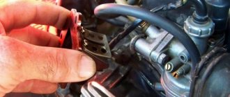
Ignition coil
The purpose of this component is a fast pulse of high voltage voltage based on a signal from the switch. It goes directly to the spark plug, where it is converted into a spark.
The coil is located on the right side of the Chinese scooter and is attached to its supporting structure. It is easy to recognize - it is made in the form of a plastic barrel. On the reverse side there is a thick wire connected. It is he who transfers the discharge according to the circuit from the transformer to the spark plug.
To protect against dirt and dust, the coil is placed in a rubber cover.
Spark plug
Its function is simple - to form a spark and ignite the mixture inside the cylinder. The scooter uses an A7TC spark plug.
Its position is hidden from view, but experienced owners know where to look for it. Having passed along the high-voltage wire, we reach the engine block and the spark plug cap.
The rubber seal protects the contact from accidental electrical breakdown. Remove with a little effort towards you. Do not pull the wire too hard - the cap may come off.
The spark plug is unscrewed with a socket wrench. After removal, you need to inspect the color of the contacts and their condition. An indicator of good engine performance is a brown tint without traces of soot. Deviation from the norm indicates a malfunction of the carburetor.
Starter
The device is used to make it easier to start a scooter engine, without using a kick pedal. The starter is located in the middle part of the moped, near the engine. To open it, you need to remove the decorative plastic.
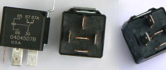
The starter is connected through the starting relay, which is located on the scooter frame.
Fuel gauge and indicator
The sensor measures the amount of gasoline in the tank and signals the need to refuel. It is located in the tank itself and is connected by three wires.
The indicator is directly connected to the sensor. Both are powered by stabilized current from the rectifier. If problems are observed in the operation of the indicator, you should check the connection to the circuit.
Voltage is supplied only when the ignition switch is turned on.
Turns relay
The breaker is used to control the turn lights. When the button is closed, the relay produces current pulses with a frequency of 1 Hz.
The block is located under the instrument panel. To change the relay you need to remove the plastic protection.
Switching the circuit is not difficult. When turning right, voltage flows through the blue wire, which is responsible for the corresponding lamps. The left position of the switch shorts the gray bus to the orange one.
Duplicate lamps on the instrument panel are connected in parallel to the turns circuit lines. They signal that the lamps are on on a specific side of the scooter.
Sound signal
The purpose of the sound horn is clear to everyone. On the scooter it is located near the limiter relay.
The signal is powered by direct current through the ignition switch and is activated by a button on the handlebars of the moped. The component is non-separable, so if it fails, it is completely replaced.