Motorcycle Ural circuit generator relay regulator
On heavy motorcycles, a 12-volt power supply kit is used, consisting of three main components - a 6MTS-9 battery, a G424 generator and a PP330 relay regulator.
Let's consider their structure and interaction.
Generator G424 is a three-phase synchronous AC electrical machine with electromagnetic excitation. Rated power - 150 W. A full-wave rectifier of the VBG-2A type is built into it, so that consumers receive direct current.
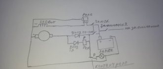
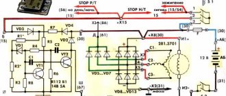
A distinctive feature of alternating current generators is very weak self-excitation. Only at a rotor speed exceeding 2400 rpm does the G424 generator begin to be completely self-service, generating electricity. Until this moment, its field winding must be powered from an external source - a battery, which is what happens when the ignition is turned on. As can be seen from the diagram, the current from the battery through the VZ terminal, the normally closed contacts of the voltage relay RN and the compensating winding RNk enters the excitation winding of the generator. The conclusion from here is simple - you cannot keep the ignition on for a long time if the engine is not running, otherwise the battery will be discharged through the field winding, which may also overheat.
If the battery is discharged, the engine can be started by connecting the flashlight battery (4.5 V) with the “plus” to terminal Ш and the “minus” to ground. This is much more effective than trying to start the motorcycle by towing.
Another feature of the generator is that it does not tolerate operation without load (breakage or disconnection of wires). In this case, its voltage reaches values that can break through the semiconductor devices of the rectifier and damage the generator itself.
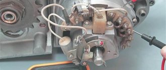
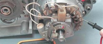
To replace a failed rectifier unit, it is enough to remove the generator fan, unscrew the nuts of the bolts securing the unit, and remove it. When installing a new unit, you need to make sure that the bolts are in place. If they come out of the special sockets, the phase leads may break off during generator operation.
The PP330 relay-regulator works in close cooperation with the G424 generator. It consists of two devices - a voltage relay RN and a relay for turning on the warning lamp RVL. The first one maintains the voltage at the generator terminals within specified limits (13.5-14 V), the second controls the lamp, which shows (when it goes out) that the generator is producing energy. The regulator does not have the usual reverse current relay, the function of which is performed by a rectifier (its diodes pass current only in one direction).
The voltage regulators PP330 and the previous PP302 operate in basically the same way. As the rotation speed of the generator rotor increases, the voltage at its terminals increases. When it reaches 13.5-14 V, the magnetic forces generated in the coil core will exceed the resistance of the armature spring and it, being attracted to the core, will open the relay contacts. The current into the excitation winding of the generator will now flow through the additional resistor Rd, due to which the current value and, as a result, the voltage at the generator terminals will decrease. This will cause a drop in the electromagnetic force on the coil, and the spring, drawing the armature towards itself, will close the contacts. The current entering the excitation winding will increase, and the voltage at the generator terminals will increase. Thus, by turning the additional resistance on and off, a certain generator voltage will be maintained.
Since the electricity consumption of a motorcycle varies dramatically in different driving conditions, for example, on a highway during the day or on dirt roads at night, the battery may be overcharged (in the first case) or, conversely, severely discharged (in the second). Both of these, if they happen often enough, will shorten the battery life. How to avoid this? The voltage regulator should be set so that the battery is not overcharged during the day, and at night you should try to drive, maintaining as high engine speeds as possible, that is, preferring lower gears to higher ones. If the battery is still “starving”, you should recharge it more often from an external source.
Re-adjusting the relay for night trips, as some drivers do, is unacceptable. Forgetting about the need for reverse readjustment, you can quickly damage the battery if you drive during the day with the main consumers - the headlight and lanterns - turned off.
Reasons for digging, there is no battery charger (it dies during operation) What we have, we bought a used generator for 250 rubles. mate part from the Internet on checking the generator - um, a curve, to be honest. what was the output and how to check. we remove the generator - this makes it easier to remove the diode bridge, since without removal, if the central contact is broken, the diode bridge supposedly works, but in reality it does not. as we check already under cut:
1. take + from the battery and connect it with a wire to one of the braided terminals from the generator with the diode bridge removed, and - from the battery through the light bulb (control) we touch one of the other 2 terminals, then the other lamp
should light up 2. take + from the battery and We connect it with a wire to one of the braided terminals from the generator with the diode bridge removed, and - from the battery through the light bulb (control) we touch the generator housing; the lamp should not light up!!! 3. We take the diode bridge and in the ringing mode we attach one probe to the mark to which the output from the bridge is screwed and we ring at the place where one of the terminals from the generator is connected, everything should ring in one direction with readings of 450-490 ohms, in the other it should not ring.
in my case, my generator had a breakdown of the central contact to the housing and a live diode bridge; the generator I purchased had a dead diode bridge.
I didn’t want to continue to trust the original relay regulator and bought a relay from a VAZ with a control lamp for 110 rubles and a relay for the lamp on the tidy to work for 90 rubles.
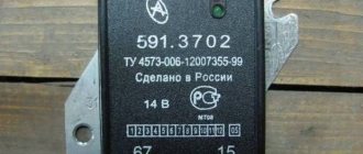
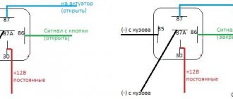
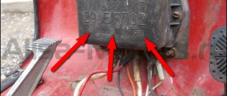
Installing a Zhiguli relay regulator on the Dnieper or Ural for example 121.3702 for 12V You will need to change the contact pairs on the wires. You will also need a normally open or closed relay (the control light will light up when there is no charge or vice versa when it appears)
We connect the wire that went to the VZ on the PP330 (the terminal on top) to connector 15 (if you install a relay, you will need a tap from this contact to the relay)
We connect the wire that went to the terminal (Ш) to the connector (67). (make sure that the wires Ш and ~ are not mixed up (disconnect the wires Ш and ~ from the generator and call them, otherwise they will suddenly be mixed up or shorted to ground somewhere.)
We attach the mass to the metal plate of the electric relay.
There are 2 wires left (they are needed for the control lamp on the tidy, you don’t have to connect them and just isolate them.
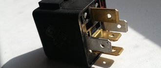
We connect the relay: We connect the wire that went to the terminal (change) PP 330 to the connector (86). We connect the wire that went to the terminal (LC) to the connector (87). We dealt with the wires hanging in the air. We connect connector (85) to ground with a separate wire. We connect connector 30 to the wire that goes to connector (15) of the electronic relay, which is also positive from the ignition switch.
Everything works and makes me happy, we continue to work, by the way, can anyone recommend a normal box that can be installed under modern fuses? I want to replace the standard one.
DIAGRAM: VOLTAGE REGULATOR
The proposed voltage regulator is intended to replace the industrial voltage regulator 33.3702 installed on Ural motorcycles. The regulator accurately maintains the voltage at 13.8 V, which ensures optimal operation of the battery.
The regulator (Fig. 1) consists of a switch on transistors VT1, VT2, a comparison device DA1, a reference voltage source VD1, R5 and an input divider on resistors R1ER4.
Resistor R3 sets the response threshold of the comparison device.
Resistor R6 provides a slight hysteresis, preventing the key transistors from switching to linear mode. Diode VD3 protects transistor VT2 from breakdown by inductive voltage during its closing.
When the ignition is turned on, +12 V voltage from the battery is supplied to connector Ш (generator excitation winding) and to the PC (indicator lamp). After starting the engine, with an increase in the number of revolutions of the generator shaft, the on-board voltage increases, and hence the voltage at the inverting input, op-amp. As soon as it becomes voltage at the inverting input, the op-amp switches transistors VT1, VT2. Closing VT2 causes the current to stop flowing through the generator field winding and the voltage decreases. This leads to switching of the op-amp and opening of transistors VT1, VT2, etc. The control lamp flashes, which indicates correct operation of the regulator.
The regulator is assembled on a printed circuit board made of foil fiberglass (Fig. 2). The dimensions of the board and the holes for its fastening correspond to the regulator board 33.3702. The location of the parts is shown in Fig. 3. Transistor VT2 is installed on a small heat sink directly on the board.
The assembled device is mounted in the housing of an industrial regulator. The surface near the M3 hole for mounting the board must be cleaned with sandpaper (or tinned) to ensure good contact between the case and the printed circuit board.
The easiest way to set up the device is directly on the motorcycle. To do this, the tuning resistor R3 slider is set to the middle position. Start the engine. A voltmeter is used to monitor the voltage on the battery. When the engine is idling, the voltage at the battery terminals is set to 13.8 V using trimming resistor R3. By adding speed and turning on the headlight, make sure that the voltage remains equal to 13.8 V. Only at idle speed and with the engine turned off, the on-board voltage should be equal to the battery voltage. After adjustment, trimming resistor R3 is blocked with paint. Attach the regulator to the motorcycle, ensuring reliable contact with the body.
Generator G-424
To understand the principle of operation of the generator and relay regulator, a little theory.
Electric generator G-424 is a three-phase machine, with electromagnetic excitation. Generates alternating current. VGB-2A rectifier converts current into direct current. For normal operation of an electric machine, a relay-regulator PP-330 . The job is to regulate the voltage of the motorcycle's on-board network so that it does not exceed 14 volts.
The G-424 generator is not able to work with a discharged battery. To start the engine and increase to 2400 rpm, the motorcycle runs on a battery. Only after this threshold is exceeded does the electric generator operate in self-excitation mode.
Generator G-424 is PROHIBITED to be turned on without load!
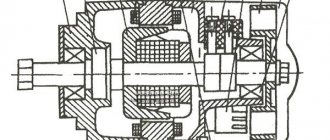
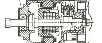
Generator circuit G-424: 1 - cover; 2 — oil seal; 3 - rotor; 4 - stator winding; 5 - terminal block; 6 — back cover; 7 — shield assembly; 8 - rectifier block; 9 - fan; 10 — protective casing; 11 - bearing.
Troubleshooting the generator
The method for determining the malfunction was as follows (I tried several methods, since replacing the relay regulator did not help):
Indirect determination of generator performance
This method does not allow you to accurately determine the malfunction of the generator, but it can still be used to determine whether the generator is “dead,” or there is still hope and the cause of the malfunction lies elsewhere.
Disconnect the wire from terminal “Ш” on the generator. And we apply + from the battery to this terminal, bring the wrench to the generator body, it should be magnetic, not much, but it is noticeable. If it is magnetic, then the rotor winding is working properly. Turn it off.
How to check the relay?
In general it was like this. I was getting ready to start my trike, which had been sitting outside all winter. After charging the battery, cleaning the contacts and replacing some substance in the gas tank with gasoline, I finally revived it. And since the ignition key was lost and the lock itself was completely broken, I could not turn off the ignition. This means the engine is working, but I don’t have the brains to take off the candle holder to turn it off (there is no engine stop). So, instead of disconnecting the positive wire going to the coil, I short it to ground. The engine died down and, in general, all signs of life along with it. I looked at the fuses, one was burned out, I replaced it, everything was still dead. To clarify, this means that the charging control lamp does not light up. Then I took a piece of wire and connected the plus directly to the coil. The lamp does not light, mind you. So I start it and the light comes on. I have a separate breaker for the generator, so I turn on the generator, the lamp starts blinking. I turn off the engine, the lamp goes out. So the main question! Which of the two relays burned out? The wiring works according to the scheme described in https://custom26.ucoz.ru/forum/5-127-1
nait9, the control light is in your hands. and check for the presence of a plus where it should be. With a multimeter in low-resistance circuits, there is little that can be adequately checked other than the integrity of the wires.
IMHO the relay-regulator burned out. When my control lamp relay burned out after a short circuit, the control lamp was constantly shining, despite the fact that the RR was regularly charging. If you buy a new RR, look for one with diagnostic LEDs. RRs are the size of a matchbox.
All is good! The topic can be closed. I decided to do as Vetal41rus advised. I checked the power supply to the lock using a test lamp. Not finding it there, I took a piece of wire and connected it directly from the plus of the generator to the lock. The lamp works, the engine starts, the gene snorts. Looks like the wire has burnt out. Remove the tank. I just filmed it again. Eh.
