INSTALLING ELECTRONIC IGNITION ON TULU
How to install electronic ignition on Tula.
Recently my Dream came true - I purchased a Tula all-terrain motorcycle - just what I needed. You can write about its merits for a long time, besides, this has been done many times before me. Therefore, I’ll immediately move on to the disadvantages - the presence on the motorcycle and the lack of batteries for sale. I don’t know what the reason was, but on my Tula they were chronically undercharged. It is clear that starting the engine with an electric starter was out of the question. And in general, it seems to me that electric start is an unnecessary luxury for a rural motorcycle. In addition, soon one battery burst and “damaged” half the motorcycle with electrolyte. A new one, of course, could not be found. My comrades advised me to install a magneto, but I didn’t get that either. A solution was nevertheless found: I equipped the Tula with a 43.3701 generator from Voskhod-ZM paired with a switch-stabilizer unit BKS 261.3734. I assembled all the electrical equipment according to the Voskhod scheme.
To install the alternator, it was necessary to make two parts: an adapter and a washer. They can be turned from any suitable duralumin blanks. I used used pistons from the K-700 tractor (for the adapter) and the GAZ-52 truck (for the washer). We also had to modify the generator rotor and oil seal housing. From the rear (facing the crankcase) side of the rotor, the metal is removed to the magnets, from the front - by 2 mm.
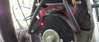
The conical part of the rotor must be bored at an angle of 7.2°. The thickness of the oil seal housing protrusion is reduced to 4 mm. The oil seal housing together with the adapter is attached to the crankcase with M6 screws, which are 5 mm longer than the standard ones. Then the rotor and stator are mounted. After this, setting the piston at a distance of 2.8-3.2 mm before TDC, rotate the stator so that the rotor slot and the sensor core on the stator take the position as shown in the figure.
The stator is fixed with three M6 screws. When setting the ignition timing, it should be taken into account that on the Tula the crankshaft rotates counterclockwise (when viewed from the generator side). For the same reason, it is necessary to swap the terminals “D” and “D1” of the sensor. The fan impeller is attached to the washer with M6 screws and pressed with an M12 rotor mounting nut. If the impeller blades touch the fan cover, cut them by 1-2 mm.
What did this change give? The weight of the motorcycle has decreased by almost 30 kg; there is no need to constantly monitor the condition of the generator and battery. In addition, and importantly, the motorcycle has become more economical: before, a full tank was enough for 200-220 km, now - for 290-300. After the modification, I rode over 5,000 kilometers on the motorcycle, and it never let me down. And the costs of re-equipment can be offset by selling the starter dyno, relay regulator, battery and ignition coil that have become unnecessary.
Modification of generator rotor 43.3701.
Modification of the oil seal housing.
Parts for installing generator 43.3701 on the Tupa motorcycle: 1 - adapter; 2 — fan mounting washer on the generator rotor shaft.
The position of the rotor and stator when marking the mounting holes.
Source
Electrical circuit diagram of the Ant scooter
Hai! This wiring diagram of the Ant equipment will be useful to those who restore old Soviet scooters. On our website All about motorcycles, such biker mechanics will find many useful images, as well as texts with tips on tuning iron horses, etc.
This resource also provides news from the world of biker sporting events.
The famous domestic scooter has become a rarity these days. Only occasionally is he encountered on the endless roads of his great homeland. You can buy it for relatively little money. On this motorcycle site you can study the technical characteristics of this utility vehicle.
Explanations for the Ant Moto wiring diagram:
1) Direction indicators with bulbs.2) Battery (battery).3) Scooter speedometer.4) Speedometer dial backlight bulb.5) Motorcycle ignition system spark plug.6) Ignition system coil.7) Ignition system capacitor.8) Switching mechanism/ turning off the high beam and the sound signal. 9) Front parking light bulb. 10) Main lighting bulb (low/high beam). 11) Turn signal switch.
12) Sound signal playback device.
13) Scooter turn signal relay. 14) Switch. 15) Night light switch. 16) Generator operation identification indicator light. 17) Neutral transmission identification indicator indicator. 18) Identification mechanism for engaging neutral gear in the gearbox.19) Motorcycle clutch.20) Bike dynastarter.21) Interrupter for the ignition system of a Soviet scooter.22) Ignition system lock.23) Ignition system fuse.24) Stop switch/switch signal.25) Moto Ant relay-regulator.26) Switch block.27) Brake light bulb.
28) Rear marker lamp.
t0shkan › Blog › My BSZ in Tula
There is no need to convince anyone that contactless ignition is a really necessary thing. Every owner of a motor vehicle puts it on literally everything that moves, even on hunchbacked Cossacks.
But if you google about installing BSZ on Ant, then complete trash comes up.
Someone came up with the idea of screwing a round curtain directly onto the shaft, which of course is logical. But there is not enough space for the sensor itself, as a result the casing is subjected to wild grinding, and all this hell sticks out outside the motor.
It looks very ugly, and while in “Ant” there may be nothing, then in Tula it definitely looks like a collective farm.
This solution requires the manufacture of an axis for attaching the curtain, and it is proposed to manufacture the curtain itself as follows:
All the videos on YouTube are dedicated to this particular implementation.
I was able to find only one video where a motor with a BSZ is briefly shown, with nothing sticking out of the casing, but exactly how the author did it is left behind the scenes.
By purchasing the figure eight ignition components and playing with them, anyone can see that the dimensions and angles in the curtain drawing above are complete nonsense. They are absolutely unnecessary; a spark jumps out even if you rustle the sensor slot with the tip of a slotted screwdriver.
In fact, when installing BSZ you need to know only 2 things:
1) A spark jumps when the curtain halfway opens the sensor.
2) For the Ant motor, this moment should occur 3 mm before TDC.
That's it, this information is enough to install the BSZ.
After removing the impeller casing and examining possible mounting locations, it became clear that the sensor needed to be mounted from above. It won't interfere with air flow, and there's just enough room to mount the sensor to the crankcase, while the shutter can be attached to the flywheel.
There are two options here: either attach the sensor without an adapter directly to the crankcase, in which case the curtain will have to be made in a Z-shape, or attach the sensor through an adapter, then the curtain will be a simple corner.
I chose the first option. I drilled a couple of holes here:
And screwed the sensor into the standard holes
The curtain was made from an old mount for a three-inch drive. You can use an old case from any desktop, there is a good tin of just the right thickness, and there are ready-made neat grooves for adjusting the position of the curtain, if necessary.
For mounting, I drilled a couple of holes in the flywheel and cut an M4 thread there (drill carefully so as not to drill through and damage the dynostarter winding). Hole depth is 7 mm.
A long crank is convenient for cutting threads; in the photo there is a tin from which the curtain is cut.
How it all spins is clear from the video
Final view - the central hole of the casing is closed with a standard rubber band, everything is beautiful
Source
Contactless ignition at Tula TMZ. Easily!
Any lover of domestic motorcycles knows that the original cam ignition is a rare slag and needs to be changed. What to change to is a rhetorical question. Of course, for normal operation you need to install contactless optical ignition.
You can at least read the instructions for the motorcycle thoroughly. The ignition on Tula will not care. You've rebuilt the cams - you've driven a little - rebuild them again.
You can come up with something with a Hall sensor, it will work. But this is already the last century. The most modern and technologically advanced solution is optical ignition based on LEDs.
I found a seller on a well-known domestic social network and signed up. The reviews are good, it doesn't look like a scam.
For those who need it, here is a link to the seller.
The trading approach is my favorite. These people clearly know how to sell a product.
The main product is the optical ignition elements themselves. If you want, you can buy only them, and buy the rest yourself.
I’m not sure about the straightness of my hands - buy the extended set, there are more details, you don’t have to do anything yourself. But for some spare parts you will have to run to the Zhiguli store.
If you don’t want to run anywhere, buy the richest set, it has everything. This is definitely enough, you don’t need to look for anything except electrical tape.
Of course, I didn’t frown at the overpayment of 200 rubles, I value my time more, and ordered everything at once, including a handful of candles, some repair kits and spare rubber bands. Everything that was available in Tula.
I feel that every year the shortage of all this tripe will only grow. It's better to take extra.
We carefully study the instructions. Let's go! Nothing complicated.
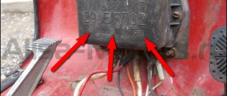
We dismantle the grille and unscrew the standard cam ignition. Goodbye source of unstable idle, we won't see you again.
Here, in fact, is the most important detail in contactless ignition - the optical sensor. In the center lies a beautiful one. For motors, scooter “Ant”, “Tulitsa” and “Tourist”) - it looks like this. For IZH motorcycles and sidecars, SZD is almost the same, very similar.
We also throw out the standard coil (ignition coil in a smart way) and the capacitor. There is no place for them in the new system.
First of all, we mount a tricky-shaped curtain made of an equally tricky material onto the flywheel. Two screws and it's in place.
Then we screw on the sealing rubber. Again two screws, again everything is simple and clear.
We install the grille, and then screw on the heart of the contactless ignition - an optical sensor with an LED.
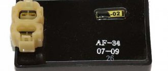
It's time to think about where to put the switch. It is advisable to install it on some kind of massive piece of hardware so that there is good heat dissipation. The most massive piece of iron in Tula is the frame.
We drop the tank and see that there is a lot of space under it, there is even a hole very suitable for a threaded rivet (comrade engineers, forgive me, of course, a hole). We drill another hole and install two threaded rivets.
Great! There's simply no better place for a switch. The perfect place.
We put the wires in a special “snake skin” type insulation and connect them according to the instructions. Again, everything is simple, if you distinguish colors, connect it.
Don’t forget to install a Zhiguli bobbin instead of the standard bobbin. They say it will be much better. There is no reason not to believe.
We adjust the ignition at top dead center. Again, everything is according to the instructions. You know what top dead center is, right? If you know, there shouldn't be any problems. If you don’t know, go play on the computer; oil-fired motorcycles are not for you.
Contactless ignition Ant, Tula (FULL set of BSZ Muravey 2.5)
How to correctly set the ignition on a VAZ 2106 with your own hands
ATTENTION: The manufacturer GUARANTEES the operation of the entire kit during initial installation. All equipment and its elements are 100% tested before shipping
It is extremely important to completely read the installation instructions, check for problems and short circuits in other electrical equipment, and use ONLY with a working battery. The warranty on consumables of the kit (switch, coil) is 14 days from the date of receipt
Although the commutator and coil have also been tested, it is impossible to guarantee a certain guaranteed period of their operation on an engine of this type, because They are designed by the factory for installation on 4T vehicle engines. If something does not work right away, then 99.9% the problem is due to incorrect installation, or damage caused by errors in the installation or operation of other equipment. During warranty service, all transportation costs for delivery of the kit to the service and back are paid by the buyer. You accept these terms and conditions upon purchase and agree to be bound by them. If you are not confident in your abilities or do not agree with the terms of the warranty, then please refrain from purchasing.
Contactless electronic ignition system Ant, Tula.
The optimal solution for high-quality engine operation is the use of so-called non-contact electronic ignition systems (BESZ).
The most important advantage of a contactless ignition system, compared to a contact one, is the supply of much more energy to the spark plug, which significantly increases the spark so necessary for fuel combustion. Thus, the combustion of the air-fuel mixture improves, which affects engine power.
No less important is the fact that the shape and stability of the pulses at all ranges of engine operation is significantly improved. This is achieved by using an optical sensor instead of a contact ignition system, which is needed to generate control pulses for the electronic switch. Thus, not only engine power and throttle response are improved, but fuel consumption is also reduced.
The third advantage and benefit of the contactless ignition system is its simplicity and low maintenance requirement. It needs to be configured once and that’s it. While the contact system is demanding in terms of maintenance and setup.
Composition of the contactless electronic ignition system kit Ant, Tula.
source
All. Optical ignition installed.
You can ride and enjoy a stable spark.
What is a stable spark? This includes even idle speed, traction under load, and finally, a beautiful, clear engine sound, and the delicious smell of burnt fuel and oil.
This is roughly how Tula drives through the snow. You can read it here, they did a special test.
In general, if you have some domestic motorcycle gathering dust in your garage, if you console yourself with the dream of restoring it, you cannot live without optical ignition.
Source
How to set the ignition timing on an Ant scooter so that the engine runs well and starts
In order for any internal combustion engine to start and “work well” (and it is the Internal Combustion Engine installed on your scooter), you need to supply fuel to it and then ignite it at the right moment. Moreover, the engine does not work in only two cases:
You are interested in the second case. So:
The work of any internal combustion engine is to convert the reciprocating motion of the piston into the rotational motion of the shaft. This transformation occurs with the help of a crank mechanism (CSM). How this transformation occurs is known from the elementary school “Physics” course.
For “good” operation of the internal combustion engine, all the fuel must burn in the cylinder within a very specific time - while the shaft rotates at a certain angle. Like the picture below:
In order for the fuel to burn at the necessary moments of movement of the piston along the cylinder, it must be ignited in a timely manner. In the Ant engine, the fuel is ignited by a spark in a spark gap called a spark plug. The ignition system, consisting of the following elements, organizes the formation of a spark between the electrodes of the spark plug:
How the listed elements work and interact with each other can be read in the same “Physics Primer” for elementary school. Here I will only remind you that a spark in the spark plug occurs at the moment the breaker contacts open. It is this moment in time that must be captured when setting the ignition timing.
“Physically” this is quite simple to do. When the current source is turned off, we clamp the strip of paper with the contacts of the breaker. Smoothly turning the engine power take-off shaft with one hand, we pull our paper strip with the other.
When the contacts release the strip, at that moment the event we need will occur in the spark plug.
Now you need to organize the “spark supply” at the required moment of piston movement. This process is also not particularly sophisticated. Insert a “match” approximately 250 - 300 mm long into the hole from the inverted spark plug. By rotating the power take-off shaft, we determine the position of the piston at top dead center (TDC) and make a mark on the match.
Well, now, by rotating the body of the breaker with a strip of paper clamped by the contacts, we catch the moment when they release the strip.
That's it - the ignition is installed, you can connect a working, charged battery and start the engine. If there is something to set on fire, the engine of your “Ant” should definitely start. More accurately, the ignition is installed with the engine running using a strobe light using special marks on the engine body.
This method of setting ignition timing is good because it does not require power to the ignition system.
That's it - good luck to you and the “ant” on the road...
Adjusting the gap between the breaker contacts
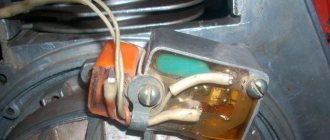
Remove the rubber plug covering the breaker from the fan cover, insert a screwdriver into the grille and turn the armature with a screwdriver until the breaker contacts are separated to the maximum possible distance from each other.
Unscrew the bolt for adjusting the contact gap of the breaker
We insert a measuring probe 0.4-0.6 mm thick between the contacts, move the breaker plate until the probe begins to move with a slightly noticeable force, tighten the bolt, turn the engine a few revolutions and check what we got: if the gap is “gone” - We re-adjust.
Instructions for installing a magneto on an Ant scooter with your own hands, video
The Ant is a versatile scooter that is used by rural and urban residents as a means of transportation, a truck, and even a tractor. Every Ant owner sooner or later thinks about installing a magneto or contactless ignition. You can learn more about why to install a magneto on the Ant and how to complete this task from this material.
Feasibility of alteration
Before installing and setting up a magneto on a scooter, think about it - does it make sense? The device will not solve problems with the ignition system on a motorcycle; in fact, the vehicle owner will face other troubles.
Magneto Installation Guide
If you decide to install a magneto, then we cannot dissuade you from it.
Detailed installation instructions are provided below:
How to set the ignition to a magneto on an ant
VIDEO ON THE TOPIC: Setting the ignition on the ant correctly!
Moreover, the engine does not work in only two cases:. The work of any internal combustion engine is to convert the reciprocating motion of the piston into the rotational motion of the shaft. This transformation occurs with the help of the crank mechanism of the crankshaft. As in the picture below:.
Parts for installing a magneto on an Ant scooter: 1 magneto adapter, 2 attachment to the dynastarter rotor, 3 attachment to the magneto rotor. Filmed on the basis of Melitopol Professional Agrarian. Ant is a universal scooter, which is used by rural and urban residents as a means of transportation, a truck and even a tractor.
How to install a magneto on an Ant scooter. For a villager, “Ant” is everything: a motorcycle, a car, a tractor, and a truck. 8 he is indispensable on the farm. And what a shame it becomes when the batteries “die”. In rural areas there has never been an abundance of them, you can’t drive them into the city (and you can’t drive a scooter anyway!), and besides, there’s no guarantee that you’ll buy them.
And without a battery, the Ant becomes weaker than its biological brother, turning into a helpless paralytic. I had to approach the problem from the other side - abandon the battery altogether. This was done by installing a magneto on the scooter from the tractor launcher of the decommissioned Belarus.
To do this, it was necessary to make an adapter, attachments for the dynastarter rotors and a magneto. They are machined from steel and then hardened. Installation is carried out in the following sequence. Having removed the coupling from the rotor, it is replaced with a magneto rotor attachment. Then, instead of the breaker, cam base and cam removed from the dynastarter, a dynastarter attachment is installed.
The latter is fixed with the same screws that secured the base of the breaker. Three holes with a diameter of 7 mm are drilled in the fan cover, necessary for attaching the magneto adapter. The adapter itself is needed to strengthen the rather fragile cover. Be sure to place plain and split washers under the fastening nuts. The cover with the adapter is fixed in place.
Having installed the piston at a distance of 2.8-3.2 mm before TDC, “put” the magneto on the adapter so that the protrusion of its nozzle fits into the slot of the dynastarter rotor. Now, turning the magneto body, you should determine the moment of opening the contacts, and then, noting the position, mark the mounting holes. M6 thread is used. All that remains is to connect the high-voltage magneto wire to the spark plug cap, and connect the wire from the terminal on the housing to the ignition switch.
In the “Off” position, this wire should be shorted to ground; in the “On” position, it should be open. Long-term operation of a scooter with a magneto is successful. No problems starting either in summer or winter, the engine runs great. The dynastarter continues to generate electricity, which is more than enough for lighting and alarm systems.
In contrast to the method of installing a magneto on a scooter, proposed by A. Platonov (“Moto”, 1992, No. 1), I think that mine is much more convenient - you only need to make three simple parts instead of five complex ones. This will require less time and expense. In addition, at any time you can quickly return to the standard dynamo battery ignition system.
Parts for installing a magneto on an Ant scooter: 1 — magneto adapter; 2 — attachment to the dynastarter rotor; 3 — attachment to the magneto rotor.