Photo report: How to check a scooter's generator?
Just like that, without minimal knowledge of electronics, at least at the school curriculum level (like mine) and a simple multimeter tester, you won’t be able to test the generator, don’t even dream about it. Before taking on such work, you should at least be able to use a tester and understand that current can be alternating or constant, know what an electrical impulse is and what resistance is. Do you know all this? Have you held a tester in your hands? If yes, then let's not hesitate.
Checking the functionality of the generator should begin with measuring the voltage that the generator itself must generate and transmit through wires to consumers. We look at where the wiring harness from the generator comes out of the engine - we move along it until we reach the connector with which the generator is connected to the on-board network of the scooter.
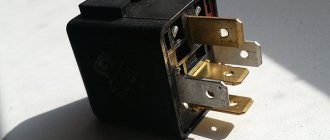
On the vast majority of scooters, the alternator connector looks something like the picture. In the common connector, there is one plug and two wires that are connected to the scooter’s on-board network through round terminals.
The plug combines the connectors of the two main windings of the generator: The working winding (yellow wire), which ensures the operation of the headlights, turn signals, lights and other consumers. And the control winding (white wire), the control winding provides voltage control in the main winding of the generator. That is, when the voltage in the operating winding of the generator increases above the specified limits, the relay-voltage regulator supplies current to the control winding of the generator, due to which the voltage in the operating winding of the generator drops to the specified limit. When the voltage drops, the reverse process occurs.
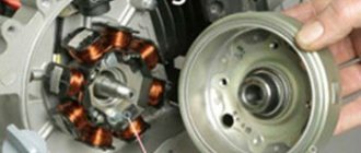
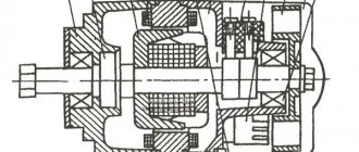
In this generator, the main windings are wound with thick copper wire on six coils.
The third winding of the generator, which is usually called high-voltage or inductive, and the magnetic induction sensor of the generator are connected to the scooter’s on-board network through round terminals.
High-voltage winding of the generator - ensures the generation of high alternating voltage (the voltage in this winding can reach 160 V or more), which directly enters the switch where it is rectified, then accumulated in the capacitor and at a certain moment in the form of a pulse is supplied to the ignition coil.
In this generator, the high-voltage winding is wound with a thin copper wire on two coils. The high-voltage winding coils are carefully insulated on the outside.
There are generators in which the high-voltage winding is wound on only one coil.
A small clarification: ignition systems in which a DC CDI type switch is installed, the high-voltage winding does not participate in the formation of a spark charge on the spark plug, so there is no point in checking it. Scooter manufacturers install a generator with a high-voltage winding, but do not use it (meaning ignition systems with a DC CDI switch). It's just wound on the generator and that's it. I will say more: due to the fact that the winding is not loaded with anything during operation of the generator, over time it simply burns out.
An example of a generator, on two coils of which a high-voltage winding that is not involved in operation is wound. I checked this winding - the tester showed an open circuit, which confirms the above.
The resistance of the generator's inducing winding is always greater than that of the other windings. The wire coming from the inducing winding of the generator is almost always red and black.
The magnetic induction sensor, when a special ledge on the generator rotor passes past it, generates an alternating pulse that opens a theristor through which the switch capacitor is discharged to the ignition coil.
Sensor in person
Ledge on the generator rotor
The wire coming from the magnetic induction sensor is almost always blue-white.
A small educational program: Traders and collective farm tusks, magnetic induction sensor of the generator, CDI ignition systems - called the Hall sensor. My dears... Maybe that's enough already?.. Where does this illiteracy come from?.. The magnetic induction sensor of the generator, the CDI ignition system, and it is this system that is discussed in this article - it has nothing to do with the hall sensor! And don’t listen to these hucksters and “gurus” who say the opposite...
The actual check itself
We switch the tester to the alternating current (ACV) measurement mode to a range of 200 V and no less. We remember that the voltage of the inducing winding can reach 160 V or more, so the measurement range of the voltage of the inducing winding must be at least 200 V.
We disconnect the plug and round terminals of the main harness - connect one probe of the tester to ground, connect the other to the terminal (black-red wire) of the inducing winding of the generator. Turn on the ignition and turn the engine with the starter. A fully operational pickup winding should produce approximately the following values.
The pulse generated by the sensor is very weak, therefore, we switch the tester to the alternating voltage (ACV) measurement mode in the 2 V range. Measuring the pulse from the sensor in a higher range may not give a result, since the tester may simply not catch it. For this purpose, use only a tester with a range in AC voltage measurement mode of no more than 2 V.
We do everything exactly the same as in the first example. The pulse from the sensor should produce approximately the following values.
By analogy with the first two examples, we measure the voltage in the working and control windings. We put the tester in the alternating voltage (ACV) measurement mode in the 200 V range and take measurements.
Well, what did you measure?.. Do all windings generate current? Or not all?.. If any winding does not produce current, then whether you like it or not, you will have to remove the generator and check it in more detail. But if the windings generate a current of approximately the same magnitude as in the pictures, then this means that your generator is in perfect order. Something like this…
In-Depth Check
We lay the generator so that the terminals of the generator windings are accessible to you. We determine the ends of the terminals of all generator windings. Finding the ends of the windings is very simple: look at the color of the wire that is soldered to the terminal block and determine what kind of winding it is.
I have marked the ends of the windings here with arrows. I selected the arrows in color in accordance with the color of the wires soldered to the terminal block. The green arrow marks the terminal block on which the ends of all windings are soldered - this is the ground terminal block.
We switch the tester to the dialing mode, take any wire from the common harness, connect any tester probe to this wire, and with the second probe touch the terminal block to which this wire is soldered. The tester should beep and show zero resistance.
If the tester is “silent” and shows numbers instead of zeros, then this means that there is a wire break somewhere or poor contact between the end terminal and the wire. Inspect the wire carefully for a break and, if necessary, replace it with a new one. We check the remaining wires, including the sensor wire, using exactly the same principle.
After checking the wires, we proceed to checking the generator windings for open circuits and interturn short circuits. We switch the tester to the continuity mode, touch any tester probe to the generator housing, and touch the end of the wire of any winding or terminal block with the second probe.
The high-voltage winding in the continuity mode should show approximately this resistance value. If the high-voltage winding does not show resistance or shows little resistance, then this means that somewhere there is an internal break or an interturn short circuit. You understand that such a malfunction cannot be “treated.”
When checking the remaining windings, the tester should emit a sound signal; the resistance of the working windings is very small, so most likely you will only see zeros on the tester display. If the tester does not emit a signal, it means there is an internal break somewhere. Such a malfunction cannot be “treated.”
We put the tester in dialing mode, touch the sensor body with any probe, touch the sensor wire or the terminal on the body to which the wire is soldered with the second probe. The resistance of the sensor winding should be approximately within these limits. If there is little or no resistance, replace the sensor with a new one.
Procedure for checking the serviceability of the alternator on your motorcycle.
All information was taken from the service book for the motorcycle and is absolutely not made up. To check the serviceability of the generator on a motorcycle , you will need a multi-meter (tester); you can purchase it at any radio-technical store or electronics store.
In general, all work on electronics and electrical work (for example, checking the serviceability of the same regulator relay on a motorcycle can only be done using a multi-meter ) requires a multimeter.
This test does not require removing the alternator from the motorcycle . With the engine NOT running (once again, DO NOT start the motorcycle during this test!).
Disconnect the terminal going to the generator , the easiest way to find this terminal is by following the wire coming from the generator, the first terminal and disconnect (3 thick yellow wires in insulation usually come from the generator and go through the entire electrical network of the motorcycle ).
Set the tester to resistance measurement mode – .
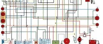
Now, according to the diagram below, measure the resistance between each winding, and then between the winding and the ground (black wire to the frame, red we measure the resistance in the terminal).
On each motorcycle, the generator has the same value between the windings, but these values may differ from one motorcycle model to another; in order to find out what the resistance value is on your motorcycle model, look in the service book of your motorcycle.
In our example ( Suzuki Hayabusa GSXR 1300 ), the resistance should be 0.2-0.2 (Ohm).
On the other hand, if you do not have a service book for your motorcycle model and the resistance value cannot be determined, then remember the following:
– if the value on one winding differs from the other two, it must be replaced.
– if the resistance value is different on all windings, the generator on the motorcycle is clearly not working properly
– also be sure to visually assess the condition of each generator winding (you will need to remove the generator cover, and then change the gasket under the generator cover, so if there is resistance, everything is in order - do not remove the cover!).