Generator Voskhod G-427
Alternating current generator G-427 with excitation from a permanent magnet with an inductive sensor of the electronic ignition system. The stator slots contain eight coils made of stamped electrical steel plates, which form four independent circuits: - power supply to the ignition storage capacitor; — light and sound signal; — direction indicators; — brake signal.
Voltage regulation in the lighting load circuits is carried out according to the principle of parametric regulation, for example, the parameters of the generator winding are selected in such a way that when the rotor speed increases, the voltage at the generator terminals changes within certain limits for a given load. Fastening the generator stator to the crankcase allows you to adjust the ignition timing.
The terminals are located on the generator stator cover: - charging coils of the power supply circuit for the Voskhod ignition storage capacitor; — direction indicators; — brake signal; - lighting; — sensor.
Which are respectively marked: >, >, >, > and >.
The sensor is attached to the generator stator cover with screws.
Generator rotor
The generator rotor with the sensor rotor placed on it is attached to the right axle axis of the engine crankshaft with a bolt and is secured against turning with a wrench.
Caring for a sunrise motorcycle generator - how to remove, what to check and install correctly
Generator maintenance mainly comes down to tightening the threaded fasteners of the generator stator and rotor, as well as the wire terminals.
In order to remove the generator, you must:
- disconnect the wires of the ignition circuit, sensor, brake light and direction indicators from the generator terminals;
- unscrew the three screws securing the stator to the crankcase and remove the stator;
- Unscrew the bolt securing the generator rotor and, with light, careful blows of a wooden hammer on opposite sides of the rotor, remove it from the trunnion and remove the key.
Checking the removed parts
After removing the generator stator and rotor, wash the parts with clean gasoline and carefully inspect them. Disassemble the wire fastening terminals on the stator. Wipe dry all insulating parts of the terminals.
Generator installation
Installation is carried out in the reverse order, in this case it is necessary:
- check the runout of the generator rotor, which should be no more than 0.1 mm with the bolt secured;
- tighten the generator stator without distortions, ensuring a tight fit to all three supports;
- install the ignition correctly;
- The generator wires must be securely fastened and well insulated from each other.
Ignition adjustment Voskhod
Ignition timing is set by rotating the generator stator after first loosening the three screws that secure the stator to the crankcase. For normal operation of the engine, it is necessary that the spark moment (on the generator, this moment is determined by the coincidence of the groove of the sensor rotor with the protrusion on the frame of the sensor coil of an engine running on gasoline with an octane number of 92).
The gap between the rotor and the sensor coil core should be 0.3 ± 0.05 mm.
The gap should be set as follows:
- loosen the screws that secure the sensor stator to the generator stator cover;
- By inserting the sensor stator into the grooves of the generator stator cover, set the required distance, then tighten the fastening screws.
To more accurately adjust the ignition, it is recommended to determine the position of the piston with the cylinder head removed.
Setting up BSZ Voskhod 3M
First, let's understand the “concepts”Ignition timing is the angle of rotation of the crank from the moment at which voltage begins to be applied to the spark plug to break down the spark gap until the piston reaches top dead center.
Ignition timing is the distance in millimeters from the position of the piston at the moment of sparking to the TDC position.
Top Dead Center is the position of the piston at which it can no longer move higher.
After compression and the piston reaches TDC, the working mixture in the combustion chamber is ignited using a spark plug. In reality, combustion of the working mixture does not occur instantly. From the moment a spark appears until the entire mixture ignites and the gas pressure reaches its maximum value, some time passes.
If the mixture ignites too early, the gas pressure reaches a significant value before the piston approaches TDC and counteracts the movement of the piston.
If the mixture ignites late, the engine will not develop maximum power, and the mixture will burn out uselessly in the exhaust system.
The most advantageous ignition timing mainly depends on the relationship between the combustion rate of the mixture and the engine speed.
According to the passport for Voskhod 3M, the ignition timing is 2.5-3.0 millimeters.
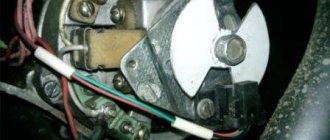
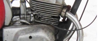
Let's remove the right crankcase cover and see what's underneath. There is a generator there. (the rest is not important to us here)
At Voskhod, different years of manufacture have different models of generators. But the operating principle is the same for everyone.
This is a single-phase AC electric machine.
The generator consists of a rotor. Rotor - from the word rotation (rotation) is something that rotates.
And the stator. Stator is from the word static (immobility), that part of the generator that does not rotate when the engine is running.
The stator, in turn, consists of a housing, inside of which coils with wire are fixed, and a cover. The cover, in theory, is rigidly fixed to the stator housing, but some people buy motorcycles in a rather deplorable state, when “the flies and cutlets are separate.” To connect everything correctly, let’s look at the picture where the cover and body are connected correctly using a special mark that you need to focus on during assembly. Please note that incorrect assembly will result in the inability to set the ignition correctly.
1. Set the piston to TDC.
2. Turn the crankshaft counterclockwise until the piston moves 2.5 mm from TDC. (For control it is convenient to use a caliper if you don’t have a micrometer).
3. Rotate the generator stator (do not disturb the position of the crankshaft) until the lug located on the rotor is visible in the slot of the stator cover.
On a 65w generator. Rotate the generator stator (do not disturb the position of the crankshaft) until the groove on the rotor coincides with the ignition sensor core.
The gap between the coil core and the magnet on the rotor must be set within 0.3+-0.05 mm.
If you have contact ignition, with the piston position 2.5 mm before TDC, the breaker cams should begin to open.
It is no secret that the assembly of motorcycle components and assemblies on the production line allows for a variation in parameters and dimensions within certain limits. (tolerances). Therefore, the ignition timing that you set is not ideal for YOUR specific motorcycle!
The next stage of adjustment. Apply any marks on the stator housing and on the engine crankcase in any way in order to know the position of the generator at the angle you set. For example, like in this picture.
Drive, remember the sensations, the operation of the engine in different modes.
Then, move the stator a millimeter or two clockwise (or counterclockwise) relative to the mark on the crankcase. Tighten the fastening screws and drive again, compare with what it was. If it gets better, perform the operation in the same direction again. If it gets worse, return the stator to its previous position.
Using this method, you can achieve the most optimal ignition timing for your motorcycle and riding style. The main parameters by which engine performance is assessed are power, throttle response, and stable idle speed. This does not mean that all these parameters must be ideal. You just need to find a compromise for yourself.
In conclusion, I would like to note that the ELECTRONIC ignition of our Voskhods, compared to other motorcycles, is simply stupid and terribly reliable. PROVEN FOR DECADES. But this is the case if you do not contribute your “know-how” to its design.
Adjustment of contact ignition.
Turn out the spark plug. Slowly turning the crankshaft, find the position at which the gap between the cams is greatest.
Use an eccentric screw to set the gap to 0.35-0.45 mm.
Rotate the crankshaft until the piston reaches the TDC position.
Using a caliper with a depth gauge, measure the position of the piston.
Add 2.5 mm to the bar readings.
Turn the crankshaft counterclockwise, while controlling the position of the piston with a bar until the latter reaches the “2.5 mm” position. to TDC"
Connect the tester in parallel with the contacts (it is very convenient to use the tester in dial mode, when the tester starts beeping when the resistance in the circuit is low. Or a battery with a test light)
Further…. WITHOUT TOUCHING THE CRANKSHAFT
Loosen the screw securing the breaker base.
Turn the base with the breaker until the lamp lights up. (if it was burning until it goes out)
Secure the base in the position where the lamp switches from one state to another (or the tester signal switches)
This is the recommended ignition timing - 2.5 mm.
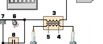
Switch Voskhod - electronic KET-1
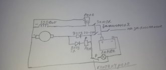
The KET-1 electronic switch is designed to work in the complete ignition system of the G-427 generator and the B-300B high-voltage transformer. This makes it possible to obtain a secondary voltage of up to 18 kV at a generator rotor speed of 250 to 7500 rpm. The switch is installed in the right tool box. The base of the switch is connected to the ground of the motorcycle. If the switch fails, it can be disassembled and repaired
The electronic switch has three lettered output terminals on the body >, > and >. The ground terminal is the base of the switch.
Maintenance of the switch during operation mainly comes down to tightening the threaded connections, while at the same time avoiding stripping the wire. It is necessary to protect the switch from moisture getting inside and on the terminals, from strong shocks and exposure to high temperatures. It is also necessary to systematically check the reliability of the electrical connection of the switch base c>, since if this condition is violated, the spark on the spark plug stops.
Planet on ignition from sunrise Sports video
How to connect the ignition from Minsk to Izh-Planeta. Adjusting the gap and some secrets. My channel https://www.yout.
This video does not contain information on its operating condition and figures for fuel consumption, piston stroke, etc. We are not Wikipe.
Ignition from Minsk to Izh Planet 3.
Two petal valves from a Sova motorcycle into a cross-country CheZet 250 type 513 and ignition from a mower. Used.
Quite often, owners of IZH motorcycles install generators with electronic ignition from Minsk motorcycles.
IZH-49 + generator “Minsk” Channel partner – forum “All about IZH-49 motorcycles” https://izh59.borda.ru/
Petrol ignition on an Izh Planet Sport engine Petrol ignition on an engine Minsk https://m.
restoration and refurbishment of Izh PS part 7, introduction of a 7 volt generator from Minsk to the Izh PS engine.
After throwing out the second hall sensor, I decided to pair the contacts with the switch. and in the end I got it.
Ignition adjustment on generators G-427, 43.3701, 80.3701, 431(432).3701, 26.3701 Pay attention to the design of the sensor.
Moto 37 presents a video dedicated to the profitable exchange of a junk motorcycle for a 1977 VOSKHOD motorcycle.
Operation of the Izh Planeta5 (Planet 5) engine with ignition from a Minsk motorcycle. No battery needed.
Spark plug Voskhod - spark ignition type A-23
During operation, the spark plug must be periodically cleaned of carbon deposits, and the gap between the electrodes must be adjusted, which should be within 0.6-0.7 mm, which is ensured by bending the outer electrode. A copper asbestos gasket is placed between the spark plug and the cylinder head to seal it. To eliminate radio interference generated by the ignition system, a shielded tip A-4 is placed on the spark plug.
Assembling the crankcase halves
We degrease the connector of the halves, knock out the guide bushings a little so that they extend 5-6 mm above the plane. Depending on your desire, we assemble the checkpoint. Personally, I assemble the gearbox only after assembling the engine, it’s more convenient for me.
We apply any automotive sealant to the connector, install the second half of the crankcase, tap it with a mallet, install the gearbox cover and tighten the crankcase with bolts.
We do not pull the bolts anyhow, but strictly according to Feng Shui: we pull about a third of the force, first the middle crosswise, then the periphery, and gradually increasing the force over several circles, we tighten the bolts as much as is sufficient.
Ignition switch Voskhod - central switch
Switch 124005490201 is used as a central program switch that provides the necessary switching of the lighting equipment on the motorcycle. The switch has three operating positions>,>,> in accordance with the following operating modes:
- in position > - the generator sensor circuit is shorted to ground, which stops the engine.
- in position > (daytime running) - the ignition circuit is on, the turn signal circuit is on (with the turn signal switch on) and the brake signal circuit (with the brake pedal depressed);
- In position > (night driving) two circuits are activated:
- a) a chain of lamps for speedometer illumination, license plate illumination and city driving (via the throttle valve, which acts as a device that integrates the parametric control of the generator);
- b) Headlight circuit A6-32 + 32 (via the light switch on the steering wheel).
Caring for the central switch comes down to periodically checking the reliability of the switch in the headlight and cleaning the moving and fixed contacts from dust and dirt by washing them in gasoline.
Contactless ignition Izh Planet / Sport (MPBSZ 1148.3734 WITHOUT coil, Sovek)
The microprocessor contactless ignition system 1148.3734 (MPBSZ) is a logical continuation of the development of electronic ignition. Model 1148.3734, which has no analogues, is designed to work in IZH PLANET motorcycles of all models with a 6 or 12 Volt generator. The microprocessor ignition module allows you to select the desired operating mode of the motorcycle engine by connecting the output wires in a certain sequence. The use of an optical sensor eliminates all the disadvantages of other spark positioning systems. MPBSZ was developed to improve the technical characteristics of the motorcycle due to: – stability and dynamic performance of the engine thanks to the function of automatically changing the ignition timing depending on engine speed; – reducing the toxicity of exhaust gases, fuel consumption and reducing carbon deposits on spark plugs, due to an increase in the inductive phase of the spark; – stable engine starting when the battery voltage decreases; – reducing the labor intensity in servicing the ignition system; – limiting the amount of current and the time it flows through the primary winding of the ignition coil to protect it from overheating and rapid discharge of the battery.
1. Rated supply voltage 6-12V with a grounded “minus” of the battery. 2. The current consumption with the ignition switch on and the engine not running does not exceed 0.10 A. 3. The system ensures uninterrupted sparking at crankshaft speeds of up to 8000 rpm. 4. MPBSZ ensures uninterrupted sparking when the voltage in the on-board network changes from 5 V to 16 V. 5. The ignition system is operational in the range of ambient temperatures from minus 25 to plus 60 degrees C. 6. The microprocessor formation of ignition timing used in MPBSZ ensures stable operation of the system in all normal engine operating modes. 7. This MPBSZ works with coil 3122.3705 or two-electrode ignition coils 3022.3705, 4412.3705, 406.3705, 3012.3705. On 12-volt models, MPBSZ is operative with ignition coil 27.3705.
MPBSZ is installed on a motorcycle using spare parts and fasteners included in the delivery kit.
The manufacturer guarantees trouble-free operation of the ignition system 1148.3734, subject to operating conditions, for 24 months from the date of sale.
More details on the website: https://sovek.com.ua/bis11483734.html
Switch P-200
Light switch with horn button (located on the left side of the steering wheel). To switch the low and high beam circuits, a P-200 type switch is used with a built-in push-button buzzer switch for three operating positions: neutral - headlight off; far right: low beam on; far left: high beam on.
The horn button has a moving contact connected to ground and a fixed contact connected to one of the wires coming from the horn terminal. When the button is pressed, the contacts close and the signal circuit is completed.
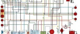
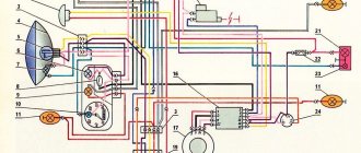
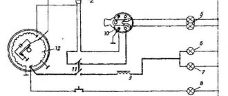
Electrical circuit of the Voskhod motorcycle
Central switch. 2 speedometers. 3. Speedometer backlight indicator. 4. Lighthouse. 5. Headlight. 6. High beam in the city. 7. Sound signal. 8. Direction indicator. 9. Direction indicators. 10. Turn signal switch. 11. Electronic switch. (D - sensor output, K - ignition coil output, D - generator output.) 12. Throttle valve. 13. Relay switch. 14. Generator. 15. License plate lamp. 16. Brake warning light. 17. Rear light. 18. Wire connection block. 19. Brake light switch. 20. Shielded spark plug cap. 21. Candle. 22. High voltage cable. 23. Ignition coil. 24. Light switch.
Thread color: sn. - blue, cf. - grey, g - blue, f. - yellow, h. - green, k. - red, box - brown, op. - orange, f. - purple, h. — blacken.
Electrical circuit diagram of the Izh Planet Sport motorcycle
Electrical circuit diagram of the Izh Planet Sport motorcycle
Hai! The improved diagram of the Izh Planet Sport motorcycle on vse-o-moto.com is not only striking, but also has a small analytical review. We will talk about what the IzhMash designers did to make this Soviet cross-country iron horse stand out from other Soviet bikes. Note that the electronics of the above-mentioned motorcycle have significantly improved the fixation, as well as the clarity of operation of all switches/switches on the steering part of the bike.
Did you know that Izh Planet Sport is the first bike from Izhevsk that was produced with 12-volt ignition system equipment. Note that most of the electrical equipment in the Izh sports circuit is unified with another Izhevsk motorcycle - “Jupiter 4”. For example, this applies to the generator, direction indicators, speedometer, optical part of the headlight, rear brake, battery, etc.
Among the electronic features of this two-wheeler you can see unprecedented devices. Their presence complicated the scheme of the sports Planet.
Explanations for the Izh Planet Sport motorcycle diagram:
1) Parking light mode lamp.2) Main front light lamp.3) Neutral transmission indicator lamp.4) Resistor.5) Oil pressure indicator lamp.6) Turn signal relay.7) Isolation unit with diodes.8) Light bulb for speedometer dial illumination.9) Motorcycle ignition switch.10) Front direction indicators.11) Headlight on/off switch, as well as emergency motorcycle ignition switch.12) Brake light on/off switch on the handbrake system.13) Relay regulator.14) On/off switch for the neutral gear lamp.15) Indicator lamp for turning on the high beam.16) Indicator lamp for the operation of direction indicators.17) Indicator lamp for turning on and operating the generator.18) A device for reproducing an audio signal.19) Switch between types of lights, as well as direction indicators . There is also a button to turn on the sound signal. 20) Motorcycle spark plug.21) Izh Planet Sport motorcycle ignition coil.22) Brake light on/off switch on the foot brake system.23) Motorcycle generator.24) Battery (battery).25) Fuse.26) Rectifier.27) Oil pressure sensor.28) Rear direction indicators.29) Rear lamp.