Chain, rear guard and sprocket (continued)
After all the unfortunate breakdowns, I went and made some goodies. I bought a new casing for the sprocket and chain, respectively, and drove it, finally bought normal turn signals and installed them.
The rear right one broke last summer when I was tinkering with the clutch drum, I had to put a late one from the 5 in its place, and the front right one broke in the fall when I was changing the oil in the gearbox.
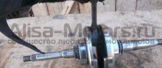
First of all, I assembled the rear sprocket.
The bearing was taken from old garage stock. I washed it thoroughly in gasoline, then filled it to capacity with grease.
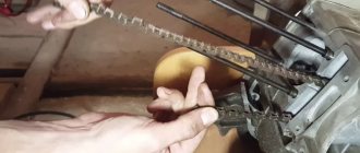
Now we assemble the casing. Well, everything is clear here. We remove everything from the old one and put it in the new one.
Here, in principle, everything is as usual, but what are new-made spare parts without jambs? You can also understand the fact that the casting is poor and I had to literally finish it with a file in full. When I connected the two halves of the casing, they did not converge due to casting jambs. Well, I filed the whole thing and everyone is happy. But when I started screwing in the bolts, I noticed that one was missing. It was a very interesting moment. Sometimes the logic of those who make these drinks is simply amazing! They didn’t put one bolt on purpose, they knew it wouldn’t be useful, but why? Yes, because one hole is drilled crookedly and there is no way to screw the bolt in there 
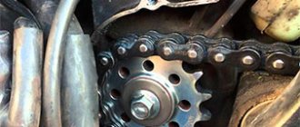
When I started installing this whole system, I started thinking that when the rear wheel didn’t want to go into place, it simply wouldn’t fit. Well, I pushed it in, installed the axle and started turning the wheel, it turned with great difficulty. I scratched my head for a long time and thought about what was wrong, because I hadn’t installed the rear brake yet, but soon aluminum shavings began to fall. In general, the wheel rubs against the casing. These were the first two moments. The third point was that when I began to tighten the axle nut, it began to tear off the casing nut. In general, there was three days of torment. The casing is not at all consistent in size; its thickness is 5 mm greater than that of a normal one. Here again the modifications began with a knife and a file, as in that joke... Having adjusted everything as it should, the question arose about the friction of the wheel on the casing. They didn't spare aluminum here either. I put the puck in and everything became okay. It’s a pity, of course, that I didn’t take the photo in the paragraph above, but I didn’t have time for that. Finally assembled and done with the back!
Next on the list in this post I’ll include painting the glove compartments. In winter, they caught well when leaving the garage. Well, I removed it, sanded it, primed it and painted it.
When we painted it, we made one big mess, but it seems like we got rid of it later, but we’ll see how the paint dries.I would also like to tell you one very interesting modification of the Izh, but I think it deserves a separate post, so one of these days there will be a post about the hydraulic clutch! That's all for today 
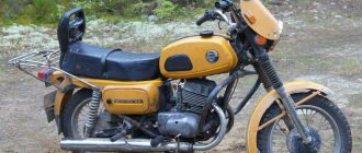
Motorcycle IZH-Planet.
Operation, maintenance and repair. >> Motor transmission, clutch, trigger mechanism. Motor transmission - replacement of chain and other parts "World of Autobooks" LLC
Motor transmission - replacing chain and other parts
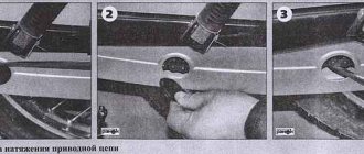
We replace the motor transmission chain if it is worn excessively. Allowable wear is expressed in the sagging of one of the branches of the chain while the other branch is tense. If the chain sags by more than 14 mm, it must be replaced. If the installed new chain sags by more than 7 mm, it is recommended to replace the drive sprocket and clutch drum.
Attention!
In spare parts, you may also find a narrower chain, with a corresponding sprocket and drum, designed for Planet 4 and earlier models. In principle, these parts are also suitable for Planet 5, but, of course, only as a kit. The resource of the “narrow” transmission is noticeably lower.
Removal and disassembly
1. To remove the chain, place the motorcycle on the center stand and engage fourth gear.
2. Drain the oil from the power unit (see p. 25). When making repairs on the road, you can, without draining the oil, put the motorcycle on its right side, remove the fuel tank or drain the fuel (if the tank is full).
3. Remove the left crankcase cover and use a caliper depth gauge, applying a ruler, to measure the sag of the chain branch.
We decide to replace the chain. In this case:
4. Remove the discs from the clutch drum as described above.
5. Remove the clutch pusher from the input shaft of the gearbox.
6. Using a 22 mm socket wrench, unscrew the nut securing the inner clutch drum clockwise (thread is left-handed). We hold the input shaft by the rear wheel to prevent it from turning (the gear is engaged).
7. Remove the nut with the lock washer.
8. Using a large screwdriver or chisel, straighten the lock washer of the crankshaft sprocket bolt.
9. Use a 22 mm socket wrench to unscrew the bolt, rotating it clockwise (the thread is left-handed).
10. Remove the bolt along with the washer.
11. Remove the motor transmission assembly.
12. Carefully remove the chain from the sprockets and remove the inner clutch drum from the outer one.
13. Remove the bushing and washers from the gearbox input shaft.
14. Remove the key from the crankshaft groove.
15. Remove two wavy shaped washers from the crankshaft.
16. Use a screwdriver to pry up the spring ring of the ratchet mechanism.
17. Remove the ring, washer and spring.
18. Remove the gear.
19. Using a suitable socket, lightly knock out the ball bearing of the clutch drum.
20. Remove the bearing.
21. We wash all removed parts in kerosene or white spirit and inspect them.
21. The teeth of the ratchet washer and the counter teeth of the gears should not be chipped, and the teeth of the sprockets should not be chipped or severely worn.
22. There should be no cracks or severe wear on the grooves on the outer clutch drum.
The clutch drum ball bearing should rotate smoothly, without noise or jamming. There should be no noticeable play.
We replace worn and damaged parts.
Installation and assembly
We install all the parts in the reverse order, while pressing the bearing lubricated with engine oil into the drum with light blows on the outer ring through the spacer (tool head).
Tighten the sprocket bolt and drum nut to the recommended torque (see p. 8). Don't forget to secure the bolt with a flexible washer!
After assembling the transmission, while the crankcase cover is not yet closed, turn the motor transmission by the rear wheel, checking the correct assembly. To facilitate rotation of the crankshaft, open the decompressor valve. The chain should roll over the sprockets smoothly, without clicks or jerks.
After installing the cover, pour oil into the crankcase if it has drained.
Contents :: Next >>
Removing the camshaft drive chain Izh 2126
- Repair manuals
- Repair manual for Izh Oda 2126 1991-2004.
- Removing the camshaft drive chain
For ease of work, remove the hood (see “Removing the hood” ) and the front cross member of the subframe (see “Removing the subframe” ). Drain the coolant (see “Replacing the coolant on a car with an UMPO-331 engine” ). We remove the coolant pump (see “Removing the coolant pump on a car with an UMPO-331 engine” ). We remove the generator (see “Removing and disassembling the generator 58.3701” ). Unscrew the oil filter (see “Changing the oil” ). Disconnect the wire from the oil pressure sensor (see “Replacing the oil pressure sensor” ). We remove the ignition distributor (see “Removing the ignition distributor” ) and its drive (see “Removing the ignition distributor drive” ). Remove the cylinder head cover (see “Replacing the cylinder head cover gasket” ) and install the crankshaft and camshaft at the end of the compression stroke of the first cylinder (see “Checking and adjusting thermal clearances in the valve drive” ).
For clarity, some of the photographs were taken with the engine removed.
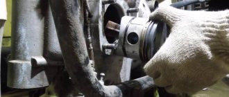
Use a bead to bend the edge of the crankshaft ratchet lock washer.
Having stopped the crankshaft from turning with a screwdriver inserted between the teeth of the flywheel ring through the clutch housing window,...
... use the 36mm head to unscrew the ratchet.
Remove the ratchet and lock washer.
Use screwdrivers to pry up the pulley and move it from the toe of the crankshaft.
We remove the pulley.
Using a 10mm wrench, unscrew the five bolts securing the top camshaft drive cover to the cylinder head...
...and two bolts securing the upper cover to the lower camshaft drive cover.
Remove the top cover and two
sealing
gaskets.
Using a screwdriver, bend the edges of the locking plates of the four bolts securing the camshaft sprocket.
Use a 10mm wrench to unscrew the bolts.
Remove the sprocket and chain from the camshaft toe.
Remove the chain from the sprocket.
Using a 13mm spanner, unscrew the six nuts securing the lower camshaft drive cover to the cylinder block (two of them, located on the left, also serve to secure the generator bracket).
Remove the generator mounting bracket from the studs.
Using a 13mm spanner, unscrew the two nuts securing the coolant channel cover.
Using a 13mm spanner, unscrew the nut securing the bottom cover, located next to the oil pressure sensor.
We unscrew the three screws securing the oil pan to the lower cover of the camshaft drive (see “Replacing the oil pan gasket on a car” ).
Remove the lower camshaft drive cover.
The joint of the lower camshaft drive cover with the cylinder block on the right and left is sealed with gaskets.
Remove the chain guide from its mounting studs.
We remove the tensioner sprocket from the chain...
...and remove the chain.
To remove the tensioner sprocket...
...we open the locking ring with pliers...
...and remove the ring and lever with sprocket from the lever axis.
Before assembly, clean the mating surfaces of the camshaft drive covers, cylinder head and cylinder block from oil and remnants of old gaskets. We install the chain guide and tensioner sprocket. Before installing the chain, make sure that the piston of the first cylinder is at TDC (in this case, the keyway of the crankshaft sprocket should be directed towards the camshaft, see the diagram of the engine camshaft drive mechanism). Having pressed the tensioner sprocket, we put the chain on the sprockets of the crankshaft and camshaft. We install the camshaft sprocket together with the chain on its toe so that the leading (left) branch of the chain does not sag. The mark on the camshaft flange should be located opposite the middle of the boss on the front camshaft support. We tighten the sprocket mounting bolts to the prescribed torque (see “Appendices” ) and secure them from turning by bending the edges of the locking plates onto the edges of the bolt heads.
We tighten the chain with the tensioner sprocket and install the lower camshaft drive cover with new gaskets. Tighten the cover fastening nuts. We install the tensioner plunger into the socket of the upper camshaft drive cover so that it does not protrude from the socket into the cover under the influence of the spring, and fix the plunger with a locking bolt. We install the upper camshaft drive cover with new gaskets and tighten its fastening bolts to the prescribed torque (see “Appendices” ) in the order shown in Fig. 1.
Rice. 1. Procedure for tightening the bolts securing the upper camshaft drive cover
We tighten the chain (see “Adjusting the tension of the camshaft drive chain” ).
Before installing the distributor drive, align the crankshaft and camshaft to the installation marks (see “Checking and adjusting thermal clearances in the valve drive” ). We install the distributor drive (see “Removing the ignition distributor drive” ). We install other components and assemblies in reverse order.
Diagram of the engine camshaft drive mechanism:
1 — track-shaft sprocket; 2 — tensioner lever with an asterisk; 3 — chain tensioner; 4 — camshaft sprocket; 5 - chain; 6 - chain damper.
↓ Comments ↓
1. General information
1.0 General information 1.1 Vehicle specifications 1.2 Vehicle and engine identification numbers
2. Engine UMPO-331
2.0 UMPO-331 engine 2.1 Design description 2.2 Oil change 2.3 Replacing the cylinder head cover gasket 2.4 Checking and adjusting thermal clearances in the valve drive 2.5 Adjusting the camshaft drive chain tension 2.6 Removing the chain tensioner 2.7 Removing the ignition distributor drive 2.8 Removing the camshaft drive chain 2.9 Replacing the front crankshaft oil seal
3. VAZ-2106 engine
3.0 VAZ-2106 engine 3.1 Design description 3.2 Oil change 3.3 Replacing the cylinder head cover gasket 3.4 Checking and adjusting thermal clearances in the valve drive 3.5 Adjusting the camshaft drive chain tension 3.6 Removing the camshaft drive chain damper 3.7 Removing the camshaft drive chain tensioner 3.8 Removal camshaft and valve drive levers 3.9 Replacing the oil seals of the timing mechanism
4. Cooling system
4.0 Cooling system 4.1 Design description 4.2 Adjusting the tension and replacing the coolant pump drive belt on a car with an UMPO-331 engine 4.3 Adjusting the tension and replacing the coolant pump drive belt on a car with a VAZ-2106 engine 4.4 Replacing the coolant on a car with an UMPO-331 engine 331 4.5 Replacing the coolant on a car with a VAZ-2106 engine 4.6 Removing and checking the thermostat on a car with an UMPO-331 engine 4.7 Removing and checking the thermostat on a car with a VAZ-2106 engine 4.8 Removing the expansion tank 4.9 Replacing the coolant temperature sensor for the instrument cluster with car with UMPO-331 engine
5. Power system
5.0 Power system 5.1 Design description 5.2 Replacing the fine fuel filter 5.3 Replacing a replaceable air filter element 5.4 Removing the air filter housing 5.5 Removing the fuel pump on a car with an UMPO-331 engine 5.6 Removing the fuel pump on a car with a VAZ-2106 engine 5.7 Dismantling the fuel pump 5.8 Removing the fuel tank and fuel receiver 5.9 Removing the carburetor throttle drive cable
6. Carburetor
6.0 Carburetor 6.1 Design description 6.2 Adjustments of Ozone carburetors 6.3 Removing the carburetor 6.4 Disassembling the carburetor 6.5 Disassembling the DAAZ-2140-1107010-70 carburetor 6.6 Disassembling the DAAZ-2107-1107010 carburetor
7. Ignition system of the UMPO-331 engine
7.0 Ignition system of the UMPO-331 engine 7.1 Design description 7.2 Replacing spark plugs 7.3 Removing the cover and rotor of the ignition distributor 7.4 Lubricating the ignition distributor 7.5 Adjusting the ignition timing 7.6 Checking and adjusting the gap between the breaker contacts 7.7 Removing the ignition distributor 7.8 Disassembling the ignition distributor 7.9 Removing the capacitor
8. VAZ-2106 engine ignition system
8.0 Ignition system of the VAZ-2106 engine 8.1 Design description 8.2 Replacing spark plugs 8.3 Removing the ignition distributor cap 8.4 Removing the ignition distributor rotor 8.5 Lubricating the ignition distributor 8.6 Adjusting the ignition timing 8.7 Checking and adjusting the gap between the breaker contacts 8.8 Removing the ignition distributor 8.9 Disassembling the distributor ignition
9. Exhaust system
9.0 Exhaust system 9.1 Design description 9.2 Removing the exhaust pipe on a car with an UMPO-331 engine 9.3 Removing the exhaust pipe on a car with a VAZ-2106 engine 9.4 Removing the resonator 9.5 Removing the muffler
10. Clutch
10.0 Clutch 10.1 Design description 10.2 Adjusting the clutch release drive 10.3 Bleeding the hydraulic clutch 10.4 Removing the master cylinder of the hydraulic clutch 10.5 Removing the flexible hose of the hydraulic clutch 10.6 Removing the working cylinder of the hydraulic clutch on a car with the UMPO-331 engine 10.7 Removing the working cylinder of the hydraulic clutch and the clutch on a car with a VAZ engine -2106 10.8 Replacing the casing and driven disc of the clutch on a car with an UMPO-331 engine 10.9 Replacing the casing and driven disc of the clutch on a car with a VAZ-2106 engine
11. Gearbox IZH-2126
11.0 IZH-2126 gearbox 11.1 Design description 11.2 Oil change 11.3 Replacing the secondary shaft oil seal 11.4 Removing the speedometer drive 11.5 Removing and installing the gearbox on a car with an UMPO-331 engine 11.6 Removing and installing the gearbox on a car with a VAZ-2106 engine 11.7 Replacing the oil seal gearbox input shaft on a car with an UMPO-331 engine 11.8 Replacing the gearbox input shaft oil seal on a car with a VAZ-2106 engine 11.9 Replacing the front bearing of the gearbox input shaft
12. Gearbox VAZ-21074
12.0 VAZ-21074 gearbox 12.1 Design description 12.2 Oil change 12.3 Replacing the input shaft oil seal 12.4 Replacing the secondary shaft oil seal 12.5 Removing the speedometer drive 12.6 Removing the gearbox 12.7 Removing the front bearing of the gearbox input shaft 12.8 Disassembling and assembling the gearbox
13. Cardan transmission
13.0 Cardan transmission 13.1 Design description 13.2 Lubricating the spline joint of the cardan shaft 13.3 Removing the cardan drive 13.4 Replacing the oil seal of the spline joint of the elastic coupling flange and the shank of the front propeller shaft 13.5 Removing the elastic coupling 13.6 Disassembling the universal joint 13.7 Replacing the intermediate support
14. Rear axle
14.0 Rear axle 14.1 Design description 14.2 Changing the oil in the rear axle 14.3 Removing the axle shaft and replacing the oil seal 14.4 Replacing the main gear drive gear oil seal 14.5 Removing the rear axle beam 14.6 Dismantling and assembling the rear axle gearbox
15. Front suspension
15.0 Front suspension 15.1 Design description 15.2 Front wheel alignment angles 15.3 Removing the ball joint 15.4 Removing the lever 15.5 Removing the anti-roll bar 15.6 Removing the spring strut guide 15.7 Replacing the hub bearing 15.8 Removing the subframe
16. Rear suspension
16.0 Rear suspension 16.1 Design description 16.2 Removing the shock absorber 16.3 Removing the spring 16.4 Removing the upper rod 16.5 Removing the lower rod 16.6 Removing the cross rod
17. Steering
17.0 Steering 17.1 Design description 17.2 Adjusting the steering mechanism 17.3 Removing the steering wheel 17.4 Removing the steering column 17.5 Removing the lower universal joint 17.6 Removing the outer tie rod end 17.7 Replacing the rack cover 17.8 Removing the steering mechanism 17.9 Dismantling the steering gear
18. Brake system
18.0 Brake system 18.1 Description of the structure 18.2 Brake pumping 18.3 Front brake pads 18.4 Replacing the rear brake pads 18.5 Removing the main brake cylinder 18.6 Removing the vacuum brake amplifier and adjusting the free stroke of the brake pedal 18.7 Removing the pedal unit 18.8 Removing the front brake hose.
19. Electrical equipment
19.0 Electrical equipment 19.1 General information 19.2 Replacing fuses and relays 19.3 Removing the mounting block 19.4 Ignition switch 19.5 Removing the ignition switch 19.6 Battery 19.7 Cooling system fan electric motor 19.8. Generator 19.9. Starter 10/19. Headlights 19.15. Control devices 19.16. Forced idle economizer control system (EFH)
20. Body
20.0 Body 20.1 Design description 20.2 Removing the radiator grille 20.3 Removing the hood lock 20.4 Removing the hood 20.5 Removing the engine splash guard 20.6 Removing the front bumper 20.7 Removing the front fender 20.8 Replacing the windshield 20.9 Removing the outside rear view mirror
21. Ventilation and heating system
21.0 Ventilation and heating system 21.1 Design description 21.2 Removing the heater valve 21.3 Removing the air blower and heater fan 21.4 Removing the additional heater fan resistor 21.5 Removing the heater radiator 21.6 Removing the heater housing, heater control unit and instrument panel air ducts 21.7 Removing the air supply duct to the rear of the cabin
22. Design features of the IZH-2717 car
22.0 Design features of the IZH-2717 car 22.1 Design features 22.2 Elements of the exhaust gas exhaust system 22.3 Removing the rear suspension shock absorber 22.4 Removing the spring 22.5 Removing the rear light, replacing lamps 22.6 Removing the license plate lamps 22.7 Removing the gas-filled stops of the hood door 22.8 Removing the hood door lock ka and him drives 22.9 Removing the hood door
23. Application
23.0 Appendix 23.1 Diagnosis of engine faults and its systems 23.2 Diagnosis of clutch faults 23.3 Diagnosis of gearbox faults 23.4 Diagnosis of driveline, rear axle, chassis, steering and brake system faults 23.5 Diagnosis of body faults 23.6 Diagnosis of generator faults 23.7 Diagnosis of battery faults 23.8 Diagnostics ignition system malfunctions 23.9 Diagnosis of starter malfunctions
24. Car body care
24.0 Car body care 24.1 Body wash 24.2 Preservation and protection of paintwork