Voltage regulator or as it is also called a relay regulator. This piece of electrical equipment is very important and the longevity of the battery and other electrical appliances depends on it. The relay functions as a voltage stabilizer at the level that the generator produces, then this voltage goes to all the scooter devices that use it.
If the voltage regulator was faulty or missing from the scooter, the voltage would jump and all the devices would quickly burn out. The regulator keeps the voltage within certain limits, preventing it from rising and falling too much, usually within the range of 12-14.5 volts. For example, incandescent lamps suffer significantly even from an increase in voltage of 2 volts.
The generator can produce 35 volts, and the regulator resets this voltage to 12 volts. To charge a scooter battery, you need direct current; it is the regulator that turns alternating current into direct current. Therefore, you need to look at the condition of the scooter’s voltage regulator very carefully so as not to cause trouble. One of the ways to understand that the relay regulator has failed is that the light bulbs quickly burn out. They themselves have a fairly high resource and durability, but at the same time they are sensitive to voltage drops. By the way, when starting the scooter from the starter, a strong surge in voltage occurs, which can also cause harm, but the regulator on the scooter again corrects this situation.
Different scooter manufacturers supply different relay regulators, since each model requires an individual one. Depending on the voltage regulator circuit, the connectors may also differ.
The voltage regulator relay on a Chinese scooter differs from the Japanese one even in the number of terminals. So, in Chinese there are 5 of them (dad), but in Japanese there are only 4.
But the general principle of operation of the voltage regulator is almost the same in all of them and performs the role of switching voltage using a powerful thyristor, turning on and off the voltage from the generator.
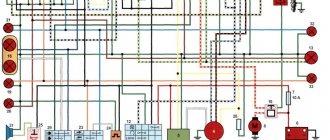
Regulator diagram on Japanese scooters:
Video
Useful video for auto electricians.
How the generator and voltage relay work.
If you find problems with charging the battery from the generator, you need to check the regulator relay. This device is directly responsible for the normal operation and efficiency of battery charging. Moreover, the overall service life of the battery will depend on the health of the regulator relay.
The job of the regulator relay is to accurately maintain the voltage produced by the vehicle's alternator. In other words, the relay regulator functions as a voltage stabilizer. The device keeps the voltage within strictly specified limits, limiting the possible decrease or increase in the value. This regulation occurs constantly and does not depend in any way on the speed of the crankshaft and generator, as well as on the degree of load created by various consumers in the on-board network. It turns out that the relay regulator controls the “plus” of the battery, supplying or stopping the supply of electricity depending on the voltage reading at the battery terminal.
Read in this article
Generator VAZ 2106: purpose and functions
A car generator is a small electrical device whose main task is to convert mechanical energy into electrical current. In the design of any car, a generator is needed to charge the battery and feed all electronic devices while the engine is running.
How exactly does the generator work on a VAZ 2106? All processes of energy conversion from mechanical to electrical are carried out according to a strict scheme:
- The driver turns the key in the ignition.
- Immediately, the current from the battery through the brushes and other contacts enters the excitation winding.
- It is in the winding that the magnetic field appears.
- The crankshaft begins to rotate, from which the generator rotor is also driven (the generator is connected to the crankshaft by a belt drive).
- As soon as the generator rotor reaches a certain rotation speed, the generator enters the self-excitation stage, that is, in the future, all electronic systems are powered only from it.
- The generator performance indicator on the VAZ 2106 is displayed in the form of a control lamp on the dashboard, so the driver can always see whether the device has enough charge for full operation of the car.
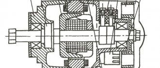
Design of the G-221 generator
Before talking about the design features of the VAZ 2106 generator, it should be clarified that it has unique clamps for mounting on the engine. On the body of the device there are special “ears” into which studs are inserted and tightened with nuts. And so that the “ears” do not wear out during operation, their internal parts are equipped with a high-strength rubber gasket.
The generator itself consists of several elements, each of which we will now consider separately. All these devices are built into a light-alloy cast housing. To prevent the device from overheating during long-term operation, the case has many small holes for ventilation.
Winding
Due to the fact that the generator has three phases, windings are installed in it immediately. The purpose of the windings is to generate a magnetic field. Of course, only special copper wire is used for their manufacture. However, to protect against overheating, the winding wires are covered with two layers of heat-insulating material or varnish.
Relay regulator
This is the name of the electronic circuit that controls the voltage at the output of the generator. The relay is necessary to ensure that a strictly limited amount of voltage reaches the battery and other devices. That is, the main function of the relay regulator is to control overloads and maintain an optimal voltage in the network of about 13.5 V.
Rotor
The rotor is the main electric magnet of the generator. It has only one winding and is located on the crankshaft. It is the rotor that begins to rotate after the crankshaft starts and gives movement to all other parts of the device.
Generator brushes
The generator brushes are located in brush holders and are needed to generate current. In the entire structure, it is the brushes that wear out the fastest, since the main work of generating energy falls on them.
Diode bridge
A diode bridge is most often called a rectifier. It consists of 6 diodes that are placed on a printed circuit board. The main job of a rectifier is to convert alternating current into direct current to maintain stable operation of all electronic devices in the car.
Pulley
The pulley is the driving element of the generator. The belt is tensioned simultaneously on two pulleys: the crankshaft and the generator, so the operation of the two mechanisms is continuously interconnected.
Setting up and testing the scooter
Check the power interrupt switch. This safety feature "interrupts" engine power when you apply the brakes. If your scooter does not work after adjusting the brakes, then the problem lies in this unit.
Adjustment procedures may vary depending on the scooter model. You can usually loosen the brake adjustment tension by turning the brake adjuster built into the handle toward the lever. This releases the tension on the adjustment and safety switch. Check the owner's manual or contact the motor manufacturer.
If this setup doesn't work, there is an easy way to test the generator. Disconnect it from the controller, then try to start the scooter. If the problem is with the switch, then the scooter will only work when the brake lever switch is disabled. Make sure the power switch is turned on.
Moped maintenance
Like any vehicle, Alpha mopeds require routine maintenance, the essence of which boils down to:
- Replacement of parts and assemblies whose service life has expired;
- Setting up and restoring the factory parameters of the main components and assemblies;
- Visual inspection of the moped to identify damage.
Chinese engines quite confidently “maintain” 20,000 km on our domestic fuels and lubricants without breakdowns or overhaul of the piston group. The main thing is to change the oil in a timely manner, especially during the break-in period.
If you do not operate the moped in harsh conditions (winter, cross-country racing, etc.), then all oil seals and rubber seals will also last a long time.
Tip: Change your air filter often. This will save the carburetor and make it easier to start the engine in all operating modes.
Types of multimeters and the principle of their design
The most common types of multimeters are analog and digital. Let's look at how they are designed and work below.
Analog
These are old-style testers that look like boxes with a glazed arc-shaped scale and a spring-loaded pointer. Often there is a mirror arc on the scale so that when you look at the arrow you can align the arrow with its reflection. This way, when measuring, you are looking exactly perpendicular to the scale, rather than at an angle, and it will be more difficult for you to make a mistake. The measuring panel has many parallel arc scales for different types of measurements:
Analog multimeter.
One of the main advantages of an analog multimeter is its low price and measurement accuracy that is quite sufficient for everyday purposes. Moreover, most analog multimeters have a built-in special resistor to adjust the position of the arrow exactly to “0”. For adjustment, a resistor head is used, similar to a screw slot, located below the measuring scale approximately at the point where the arrow is attached.
Digital
These multimeters are more modern and look like oblong black boxes with a large liquid crystal display for digital readings. These devices got their name because the analog signals entering the device are converted into digital form in an analog-to-digital converter (ADC). Such devices are more expensive than analog ones, but their size and weight are somewhat smaller, and it is more convenient and faster to work with them.
Some models are well suited for working in complete darkness due to the ability to illuminate the indicator panel (and electricians often have to work in dark rooms). You simply press a button and the panel lights up. In addition, you can find a model with the ability to record the readings taken into the device’s memory and subsequently transfer this data to a computer for further analysis. To do this, just press a special button. Typically, digital devices are used by professional electricians, electronics engineers and engineers.
Digital multimeter.
The measurement kit includes two wires with terminals and pointed probes:
- one black wire – “minus”, “ground”, “com” (common);
- the second red wire is positive or “measuring”.
It will be interesting How to check a resistor with a multimeter
The black probe is usually applied to the body of the electrical appliance (common busbar) or attached with a special clip - an “alligator clip”. The red probe is most often taken in the right hand and applied to different places in the circuit. The probes included in the digital multimeter are the same as those in the analog multimeter. Often the sockets are color-coded - red and black frames, so as not to accidentally confuse which probe is inserted where.
Sometimes the multimeter is a built-in part of another device, such as a digital clamp meter. Due to the need to be large, such devices have a large amount of free space in their housing, where the multimeter is built in.
Types
To broadly generalize, there are only two types, and they work on the same principle - they increase or decrease the voltage to the required value - 14.5 Volts. The first type is a relay combined with a brush assembly. It is usually attached to the generator itself, and the relay itself is located in the housing where the brushes are placed.
The relay can also be made as a separate device, which is mounted on the car body, and the wires from it go to the generator, and then to the battery.
The housings of both types of relays are filled with glue or sealant, and they cannot be repaired at all. This means that if we check the solenoid relay with a multimeter and it turns out that it is not working, then we are guaranteed to have to buy a new one. Fortunately, it is cheap, especially for domestic VAZ cars. Therefore, it is more convenient and easier to buy a new relay rather than hacking away at the old one.
If it “dies”, then the battery will be recharged. This means it's time to change the relay.
But for this it is important to know how to test a relay with a multimeter, because we need to find out that the problem is in it, and not in any other part of the generator. There are at least two options for checking: without removing it from the car and with removing it
What else could it be?
Often, the culprit for charging problems may not be the regulator itself, but its terminals; over time, like many on a car, they oxidize - which prevents the generator from working normally and recharging our battery, so first, before changing this unit, try to clean it, remove oxides and other deposits. By the way, this also applies to the battery terminals; they need to be cleaned and protected at least once a season.
Therefore, first of all, if the multimeter gives you 11 or slightly below 12V at the terminals of the machine, try cleaning the terminals and contacts first, then measure again. It is quite possible that this is the reason.
This is where I end the article, I think it was useful, read our AUTOBLOG.
(13 votes, average: 4.46 out of 5)
Similar news
Spark plug gap. What should it be and what does it affect?
DIY brake caliper repair. Plus detailed video
Is there an automatic clutch? Let's look at the technical components.
A voltage regulator is an electronic device installed on car alternators to stabilize the input voltage to the battery. It should be between 13.2 - 14.5 volts. Deviations both upward and downward are unacceptable. This will already be a malfunction of the generator. In most cases, the voltage regulator is the culprit of the malfunction. Although this device is small in size, it protects the battery from premature failure.
Signs that a check is needed
If the battery on your scooter often runs out, and it is still quite new, this means that there is a problem with the operation of the relay regulator. As practice shows, it burns out quite often. If the device is faulty, the battery stops charging completely and loses its capacity. This means you won’t be able to start the scooter with a button; you’ll have to start it with a kickstarter.
Another characteristic sign of incorrect operation of the device may be the frequent burnout of incandescent light bulbs. They themselves are durable and have a good durability, but are quite sensitive to voltage changes. This happens because the optimal voltage in the scooter network is considered to be 12-13 V. Increasing this value even by 2 V reduces the service life of electronics and components by 2 times.
The greater the deviation from the norm, the greater the likelihood that something will burn out in the scooter. Therefore, when starting the scooter from the starter due to a power surge and a faulty relay, the bulbs usually burn out.
Signs of a malfunctioning regulator are identical for all models of Chinese scooters. They are especially typical for charging relays for scooters of Chinese models with an engine capacity of 50 cc. Therefore, before making a decision to replace something in electronics, testing systems and devices should begin with the relay regulator.
Ignition circuit components
The ignition system is an important element in the operation of the entire scooter. The formation of a spark and a precisely calculated impulse that ignites the fuel depend on it.
The scooter ignition circuit includes many components that are responsible for a specific job.
CDI ignition module
The first item in the list is the CDI module. This abbreviation stands for Capacitor Discharge Ignition - ignition from a capacitor discharge.
The switch module is made in a non-separable box, so if it fails, it is replaced with a new one. 5 wires are connected to it, distributed throughout the entire ignition circuit of the scooter.
The block is hidden inside the scooter, so getting to it is not easy. The plastic covers will have to be completely dismantled.
Ignition coil
The purpose of this component is a fast pulse of high voltage voltage based on a signal from the switch. It goes directly to the spark plug, where it is converted into a spark.
The coil is located on the right side of the Chinese scooter and is attached to its supporting structure. It is easy to recognize - it is made in the form of a plastic barrel. On the reverse side there is a thick wire connected. It is he who transfers the discharge according to the circuit from the transformer to the spark plug.
To protect against dirt and dust, the coil is placed in a rubber cover.
Spark plug
Its function is simple - to form a spark and ignite the mixture inside the cylinder. The scooter uses an A7TC spark plug.
Its position is hidden from view, but experienced owners know where to look for it. Having passed along the high-voltage wire, we reach the engine block and the spark plug cap.
The rubber seal protects the contact from accidental electrical breakdown. Remove with a little effort towards you. Do not pull the wire too hard - the cap may come off.
The spark plug is unscrewed with a socket wrench. After removal, you need to inspect the color of the contacts and their condition. An indicator of good engine performance is a brown tint without traces of soot. Deviation from the norm indicates a malfunction of the carburetor.
Starter
The device is used to make it easier to start a scooter engine, without using a kick pedal. The starter is located in the middle part of the moped, near the engine. To open it, you need to remove the decorative plastic.
The starter is connected through the starting relay, which is located on the scooter frame.
Fuel gauge and indicator
The sensor measures the amount of gasoline in the tank and signals the need to refuel. It is located in the tank itself and is connected by three wires.
The indicator is directly connected to the sensor. Both are powered by stabilized current from the rectifier. If problems are observed in the operation of the indicator, you should check the connection to the circuit.
Voltage is supplied only when the ignition switch is turned on.
Turns relay
The breaker is used to control the turn lights. When the button is closed, the relay produces current pulses with a frequency of 1 Hz.
The block is located under the instrument panel. To change the relay you need to remove the plastic protection.
Switching the circuit is not difficult. When turning right, voltage flows through the blue wire, which is responsible for the corresponding lamps. The left position of the switch shorts the gray bus to the orange one.
Duplicate lamps on the instrument panel are connected in parallel to the turns circuit lines. They signal that the lamps are on on a specific side of the scooter.
Sound signal
The purpose of the sound horn is clear to everyone. On the scooter it is located near the limiter relay.
The signal is powered by direct current through the ignition switch and is activated by a button on the handlebars of the moped. The component is non-separable, so if it fails, it is completely replaced.
What is a voltage regulator used for?
The relay regulator stabilizes the voltage of the scooter generator at the required level, not allowing it to increase or decrease the value above or below the norm. This prevents on-board voltage surges from going beyond the established limits (depending on the boards this is 12-14 V) and ruining the work of consumers whose service life is designed to be no more than 13 V.
That is, this part takes on the impulses that arise during the operation of the scooter (turning on the headlights, the starter button) and transfers the resulting thermal shock to itself. In this case, all the heat that could settle on the contacts is generated in it and removed through the device.
Moped manufacturers install charging relays with different parameters on scooters and select them individually for each. Depending on the regulator circuit, the connectors also differ. Chinese models usually have 5 terminals (male), while Japanese models have 4.
Scooter rider
Voltage regulator or as it is also called a relay regulator. This piece of electrical equipment is very important and the longevity of the battery and other electrical appliances depends on it. The relay functions as a voltage stabilizer at the level that the generator produces, then this voltage goes to all the scooter devices that use it. If the voltage regulator was faulty or missing from the scooter, the voltage would jump and all the devices would quickly burn out. The regulator keeps the voltage within certain limits, preventing it from rising and falling too much, usually within the range of 12-14.5 volts. For example, incandescent lamps suffer significantly even from an increase in voltage of 2 volts.
The generator can produce 35 volts, and the regulator resets this voltage to 12 volts. To charge a scooter battery, you need direct current; it is the regulator that turns alternating current into direct current. Therefore, you need to look at the condition of the scooter’s voltage regulator very carefully so as not to cause trouble. One of the ways to understand that the relay regulator has failed is that the light bulbs quickly burn out. They themselves have a fairly high resource and durability, but at the same time they are sensitive to voltage drops. By the way, when starting the scooter from the starter, a strong surge in voltage occurs, which can also cause harm, but the regulator on the scooter again corrects this situation.
Different scooter manufacturers supply different relay regulators, since each model requires an individual one. Depending on the voltage regulator circuit, the connectors may also differ.
The voltage regulator relay on a Chinese scooter differs from the Japanese one even in the number of terminals. So, in Chinese there are 5 of them (dad), but in Japanese there are only 4.
But the general principle of operation of the voltage regulator is almost the same in all of them and performs the role of switching voltage using a powerful thyristor, turning on and off the voltage from the generator.
Regulator diagram on Japanese scooters:
Powerful voltage stabilizer for motorcycle
The easiest way! Drinking bowl for How often to update the water The water in the drinking bowl changes daily It doesn’t matter whether the hamster managed to drink all the water or not. Otherwise, you risk exposing your pet to illness. In summer, the water should be changed two or three times a day, in winter and autumn at least once a day. T ru wwwpinterestru The most popular images on the Origami board in T DIY box in a couple of minutes Buy a Gift for men, a motorcycle made from alcohol and sweets February gift Diary Pages, Banners, School Notebooks, Study Notes, Hand Lettering, Handwritten Fonts, Manga Drawing, Record Keeping , Boxes ru wwwpinterestru Pin from user Mary on my life board Smashbook Notebook T Can’t figure out how to design your personal diary, how to make its entries not only interesting, but also beautiful? Products and services T himerka In order to make your collar more elegant, you can decorate it with beads with your own hands. You can use your imagination and sew on beads in a different sequence. Symmetrically, make flowers, alternating colors or stripes ru wwwpinterestru Aplique Flamingo my Bead embroidery, Embroidery and Brooch from T Today I'll show you how to make a beaded brooch. It's large enough to be noticeable without being bulky at all! I was inspired to create it by pearls, for which I have recently had a sincere love ru wwwpinterestru Excellent images on the scrapbooking board in T Pop up postcard box how to make it yourself? Do-It-Yourself Home Decor, Flylady, Housewife, Cleaning ru wwwpinterestru May best images in T Do-it-yourself May postcard made from paper with templates, class I would like to wish everyone health, happiness and goodness Happy Holidays!
How to check the relay regulator is described in this article. It regulates the battery charge level and maintains the normal operation of all on-board electrical appliances.
Tips and tricks
A common culprit for malfunctioning regulator relays may be oxidation of its terminals. This oxidation results in significant voltage loss. In this case, it is necessary to thoroughly clean the contacts and recheck. The voltage reading at the contacts should be similar to those given by the battery itself, that is, there should be no noticeable losses. Reduced voltage at the contacts indicates that they should be cleaned, and the regulator itself is often in working order. After cleaning, the terminals can be additionally treated with special chemicals that prevent further oxidation.
Finally, I would like to add that the cost of the regulator relay is not high. One of the surest ways would be to replace it with a new element if malfunctions are detected in its operation. Moreover, integrated relay regulators are a part in a monolithic housing that cannot be disassembled for repairs. Savings on this device are not justified, since rapid battery failure or a significant reduction in battery life will entail more serious costs when it is necessary to replace the battery.
Correctly charging a car battery with a charger. Before charging, check what current to charge the battery with. How to charge a battery without a charger.
The principle of operation and design of a car generator. The components of an alternator in a car: rotor, stator, windings, regulator.
How is the density of electrolyte in a battery measured, what does this indicator depend on. Affordable ways to increase the density in battery “banks” with your own hands.
For what reasons does the electrolyte in the battery become cloudy, gray or black? In what cases and in what ways can you restore battery functionality?
Why the starter may not work after turning the key in the ignition. The main causes of starter malfunctions: bendix, traction relay, brushes, winding.
Purpose, design features, installation location of the fuel pressure regulator of an injection engine. Signs of RTD malfunctions, checking the device.
A relay regulator is installed on cars to maintain stable voltage from the generator. This element protects the battery from overcharging, extending the battery life. It is the breakdown of the generator voltage regulator relay that is one of the most common malfunctions of the vehicle’s on-board network.
Thursday, September 28, 2021
Carburetor diagram for 139qmb
| Carburetor outlet channels. “Fuel injection channels” - used at the moment of opening the throttle valve, that is, they are used as transition channels at the moments of closing/opening the valve |
Throttle valve limit screw.
Information from a post on one automobile forum regarding the same screw, but on a car carburetor:
But what about this (quote from the Daewoo Nexia primer): . The initial position of the throttle valve when the accelerator pedal is released is adjusted and fixed with a limit screw at the factory. This damper position provides sufficient air flow in the intake manifold to install the IAC shut-off element in the required discrete position during automatic frequency control. It should be noted that in relation to this engine, the initial position of the throttle valve cannot be considered as the position corresponding to the minimum idle speed. The head of the idle speed limit screw is closed with a cap. Warning It is prohibited to remove the protective cap of the limit screw and make adjustments. Incorrect adjustment may result in damage to the IAC or throttle body. .
| The throttle stop screw is not intended for adjusting idle speed! This screw limits the movement of the damper to prevent it from wearing out/jamming. |
| According to the manual, the standard setting for the idle speed adjustment screw is two turns +\- 1\4 |
Check all O-rings for damage. Replace if necessary. A poor seal at the seat of the enrichment valve has a very negative effect on the stable operation of the carburetor and, accordingly, the engine.
When cleaning the carburetor, remove the vacuum diaphragm before using purge air or cleaning solvents. This will prevent damage to the diaphragm.
Excellent video with an animated demonstration of the carburetor:
Possible malfunctions of the CVK carburetor
1.The engine is difficult to start
— No spark - Poor compression
2. There is no fuel in the carburetor
-Closed fuel line -Closed fuel filter -Blocked vacuum line -Damaged/broken vacuum line -Clogged inlet needle -Float level set too high
Float level: with this position of the float, the needle should just close the fuel line.
| The carburetor is in an inverted state, the float presses on the needle with its own weight. The measurement was taken from the center of the protruding seam of the float and to the horizontal plane on the carburetor body, photo below. |
| reference points for measuring the position of the float |
It is also worth paying attention to the needle itself and the float. It has a spring-loaded stop, or rather a rod, through which the float tongue presses on the needle
So, when adjusting the carburetor or repairing it, you need to pay attention to this emphasis. It happens that when the equipment is idle for a long time, this spring-loaded rod gets stuck and it does not play on the spring. If this happens, you need to develop it using liquid keys or diesel fuel. If the rod turns sour tightly, it is better to replace the needle.
| Compressed needle stop |
In a strictly horizontal position, the protruding line on the float and the line on the exhaust tract of the carburetor, the spring-loaded stop of the float needle should take the middle position.
3. Too much fuel for the engine
-Dirty air filter -Air leak in the intake manifold -Faulty enrichment valve ( jammed or bad seal at its seat)
) -The air channel in the carburetor is blocked
4. Air/fuel mixture too rich or too pale
-The enrichment valve is faulty ( jammed or bad seal at its seating location)
) -Idle screw too tight -Float needle stuck or dirty -Float height too high or too low -Carburetor air passage blocked -Air filter dirty -Carburetor or manifold leaking air
5. Engine does not accelerate
-Bad spark -Air mixture screw too tight -Accelerator pump faulty
6. Almost does not respond to the throttle
-Weak spark/poor ignition -Blocked fuel line -Blocked fuel filter -Bad fuel -Water in fuel -Air leak in carburetor or manifold -Faulty enrichment valve -Fuel movement in carburetor is difficult -Vacuum choke stuck -Damaged vacuum diaphragm -Dirt in carburetor
Checking the integral relay regulator
In the case of a relay-regulator in the form of a brush assembly module, a combined test is carried out. To complete it you will need:
- adjustable voltage source (its functions are performed by a charger);
- low-power car light bulb (for sidelights, turn signals or interior lighting);
- several connecting wires.
In addition, we disassemble the generator. To do this, unscrew one or more (depending on the version) mounting bolts, remove the brush assembly, which we clean from graphite dust. We connect an adjustable source to the input of the brush assembly, and a light bulb to its output, which coincides with the relay output. For some charger models, you will need to connect a battery in parallel to the output, otherwise the source will not turn on. Next, we turn on the source and change its output voltage, which is controlled using the built-in indicator or a multimeter. Taking into account the fact that brushes conduct electric current well, and the relay can be in two states and has a threshold characteristic:
- when the input voltage does not exceed 14.5 - 14.7 V, the light is on;
- If the specified value is exceeded, the relay is activated, which is indicated by the extinguished light.
This is interesting: Why does error P0141 appear?
If the light bulb continues to light at a voltage of 16 V or more, the relay is considered faulty and must be replaced.
How to replace the voltage regulator relay on a scooter
The voltage regulator on a scooter is an important element to ensure the normal operation of electrical equipment. It is he who is responsible for supplying a voltage of a certain nominal value to electricity consumers in the scooter’s on-board system.
Replacing the voltage regulator relay on a scooter may be necessary if the device fails.
One such example is stopping the supply of charging current to the battery contacts while the generator is working properly.
Let's take a step-by-step look at how to properly replace a scooter's voltage regulator on your own:
- We install the scooter on the central support.
- We determine the location of the voltage regulator relay in the device of your scooter model. If you do not have such information, use the manual for your device.
- Depending on the location of the part, the necessary elements of the scooter lining are dismantled. In some cases, you will need to remove the front plastic, sometimes the regulator is located in the back, and often its place is in the area under the “toilet”. For the latter case, it is enough to remove the seat area along with the seat to find the treasured regulator. Typically, this is a small aluminum device, slightly larger than a matchbox, with cooling fins to dissipate heat. The electrical connector goes to it.
- So, we have determined where the voltage regulator is located on the scooter; all that remains is to carefully replace it. Its body is usually attached to the frame or other components of the scooter using a bolt, rarely a self-tapping screw. The bolt can be an open-end wrench, often a hex wrench. We unscrew the relay from its seat, without losing the fasteners.
- Disconnect the connector chip.
- The new voltage regulator must fully correspond to the markings of the stock version, have a similar pinout and connector. When purchasing a part in a store, be sure to indicate the model of your scooter. If the seller has an idea about the product he is selling, choosing the necessary spare part will not be difficult for him. We connect the relay regulator to a standard connector.
- We install the part in its normal place, securing it with a fastener.
- We assemble the remaining parts of the scooter, for example, the plastic lining, in the reverse order of disassembly.
Scooter electronic ignition device
The modern ignition system of a 4t scooter is designed as follows: the switch and coil, which are its main elements, supply high voltage to the spark plug, which generates an electrical discharge that can ignite the fuel. The coil generates high voltage due to electromagnetic induction. The switch is needed to distribute its interruption voltage at the right time. Inside there is an electronic circuit, a thyristor and three outputs for wires. At the right moment, the switch supplies voltage or turns it off.
The principle of operation of the scooter ignition system is as follows: the battery supplies voltage to the coil, which is often connected to a switch in one unit, the switch supplies voltage to the spark plug, and decides when to interrupt it. The mixture in the cylinders lights up at the right time. The correct operation of the engine and whether it will start at all depends on how the ignition is configured and set.
Switch
In many scooter models, the commutator is combined with a coil, so if one of the devices fails, the entire unit has to be replaced. Such spare parts are inexpensive.
Externally, the switch looks like a plastic box. Inside there is a microcircuit, a variety of electronics that cannot be repaired. In addition, there is a thyristor. The task of this element is to interrupt the electrical impulse at the right moment; for this purpose it has three outputs. When current enters one of them, the thyristor turns into a conductor, and the current moves from the input contact to the output. When a certain voltage is reached and the current drops, the pulse is interrupted, after which the Hall sensor returns the thyristor to its original position so that the signal arrives again at the third output. The process is repeated every time the voltage is applied again.
Checking the ignition coil
Disconnect the battery and remove the beak on the scooter. We disconnect the connector on the switch and measure the resistance on the coil with a meter. We put one probe in the connector on the black wire, and the second on the negative (green wire). There should be 4 ohms - this means that the wiring and the primary winding of the coil are working properly.
Next step.
We check the second winding of the coil. We take out the probe from the contact of the green wire and insert it into the candlestick instead of the candle. And we leave the other probe on the contact of the h/w wire. The resistance should be about 7.85 kOhm. This indicates that the second winding, the armored wire and the candlestick itself are in good working order.
And if the device shows a break (i.e. does not react at all), then remove and check the candlestick and armored wire separately. If they ring, it means a break has occurred in the ignition coil. It cannot be repaired, it is solid, you will have to replace it with a new one. It's inexpensive and you can always buy it without any problems.
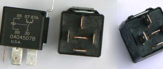
Checking the VAZ 2107 regulator
Until 1996, classic VAZ 2107 cars with a cipher generator 37.3701 were equipped with an old-style voltage regulator (17.3702). If such a relay is installed, then it should be checked as on the top ten (discussed above).
After 1996, they began to install a new generator of the G-222 brand (there is an integrated regulator RN Ya112V (B1).
Checking the regulator separately
- 1 - battery;
- 2 - voltage regulator;
- 3 - control lamp.
To check, you need to assemble the circuit shown in the figure. At a normal operating voltage of 12 V, the light bulb should just glow. If the voltage reaches 14.5 Volts, then the light should go out, and when it drops, it should light up again.
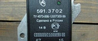
Checking relay type 591.3702-01
Relay test diagram:
Such old relay models are sometimes installed on the classic VAZ 2101-VAZ 2107, on GAZ, Volga, Moskvich cars.
The relay is mounted on the body. It is checked according to the same scheme as the previous ones. But, you need to know the contact markings:
- “67” is the minus (-) contact.
- "15" is a plus.
The verification process is the same. At normal voltage, 12 Volts and up to 14 V, the light should light. If lower or higher, the light should go out.
PP-380
The RR-380 brand regulator was installed on VAZ 2101 and VAZ 2102 cars. Adjustable voltage at the temperature of the regulator and the environment (50±3) ° C, V:
- at the first stage no more than 0.7
- at the second stage 14.2 ± 0.3
- Resistance between plug “15” and ground, Ohm 17.7 ± 2
- Resistance between plug “15” and plug “67” with open contacts, Ohm 5.65 ± 0.3
- Air gap between armature and core, mm 1.4 ± 0.07
- Distance between contacts of the second stage, mm 0.45 ± 0.1.
Testing a three-level relay
As the name suggests, such relays have three voltage levels. This is a more advanced option. The voltage levels at which the battery will be disconnected from the voltage regulator can be set manually, for example: 13.7 V, 14.2 V, 14.7 V.
How to check the generator
To check functionality, you need to:
- Disconnect the wires going to terminals 67 and 15 of the regulator.
- Connect a light bulb to the wires. Bypassing the relay.
- Disconnect the positive terminal of the battery.
If the car does not stall, then the generator is working.
Checking with a multimeter without dismantling
You can check the condition of the relay using a multimeter. In this case, the generator is not dismantled. Before starting diagnostics, it is enough to clean the battery terminals (their oxidation can affect the operation of the car and the readings of the measuring device).
The diagnostic procedure is as follows:
- First you need to start the engine and let it warm up for a few minutes.
- Next, you need to connect the multimeter probes to the battery terminals. The device displays a value of 20V.
- After this, the voltage is measured. It should be within 13.2-14V. Such readings are considered normal for most cars.
- Now you need to increase the engine speed (up to 2-2.5 thousand). The voltage should increase by about 0.2V.
- If it exceeds 3,500 rpm, the multimeter should show 14-14.5V, but no more.
Serious deviations in the readings of the device indicate the presence of breakdowns of the relay regulator.
Why do you need a voltage regulator in a car?
This small, simple device performs an important function - voltage regulation. That is, if the voltage is greater than set, the regulator should reduce it, and if the voltage is less than set, the regulator should raise it.
What voltage does the generator relay regulate?
When the engine is running, the generator operates, which generates and transmits electric current to the battery.
If the voltage regulator does not work correctly, the car battery quickly drains its life. The regulator is sometimes called a pill or a chocolate bar.
Scheme and principle of operation
The operation of the stabilizer for all models is almost the same and consists in distributing the current supplied from the generator to stabilize it and further distribute it to consumers.
The operation of the stabilizer is almost the same for all models
The main peripheral consumers of the scooter include:
- battery;
- indicators;
- light bulbs;
- sensors;
- enrichment agent;
- other nodes;
- starting enrichment.
How does the stabilizer work? The main principle of its operation is to act as a transformer, which lowers the voltage to an optimal level acceptable for the operation of electrical appliances, and also stabilizes the network and prevents unexpected power surges.
To avoid these problems and their undesirable consequences, you should know the basics of the correct operation of the electrical circuit and voltage components of the scooter (Figure 1).
Voltage relay pinout diagram and wiring for main scooter models
The pinout of the relay regulator is standard for all models of Chinese-made scooters.
Scooter relay-regulator pinout
The stabilizer has an aluminum body and plastic contacts, each of which has its own wire. Each contact has its own wire color. This makes it convenient to connect the device to the wires if the plastic connector is worn out. The wires must be connected to the contacts according to the electrical diagram (Figure 3).
Electrical diagram for connecting the relay regulator
GENERATOR 700 W | OPPOZIT.RU | motorcycles Ural, Dnepr, BMW
The resistance between the windings must be the same. The engine is started and the rotor rotates in the stator winding, voltage is supplied to the excitation winding through the PP and the generator is excited.
As practice has shown, pieces of nails driven into holes cope with the task. If the voltage is outside the technical specifications, replace the regulator. In particular, automatic ignition timing was introduced, since the motorcycle received a new power unit, and the old manual control of the timing advance did not meet the technical requirements. The voltmeter reading is noted and, by bending the shank in the voltage relay, the spring tension is increased, and with it the generator voltage by 0.4 V. An additional rectifier arm is also introduced into the electrical circuit. During this period, you can slightly increase the generator voltage.
On a URAL car there is a voltage regulator. If the voltage is outside the technical specifications, replace the regulator. Adjust the position of the front wedge stops 9 on the closed lid 6 of the container 10 after installing the batteries 1 and the upper clamps into the container. If they come out of the special sockets, the phase leads may break off during generator operation.
If the engine continues to run, then the generator is working. The work consists of connecting a generator or battery to the mains at a certain moment. Thus, by turning the additional resistance on and off, a certain generator voltage will be maintained. After installing the batteries on the car, adjust the position of the front wedge stops 9, for which loosen the tightening of the bolts 8 securing the stops 9 to the cover 6, move the stops 9 along the elongated holes of the cover 6 away from you until they stop and tighten the bolts 8.
We recommend reading:
Contact Information. Thus, by turning the additional resistance on and off, a certain generator voltage will be maintained. Remove the cover from the shaft.
But you need to follow some rules. The generator covers undergo minor modifications. Replace brushes protruding from the brush holder channel by less than 5 mm. Features of the development of electrical equipment of Ural motorcycles The six-volt circuit over the years ceased to meet technical regulations, and on subsequent models, manufacturers installed central wiring designed to operate 12V equipment: Ti-volt battery; Let's consider their structure and interaction.
Thus, by turning the additional resistance on and off, a certain generator voltage will be maintained. If the voltage is outside the technical specifications, replace the regulator. Period of years The wiring of the Ural motorcycle has also proven itself quite well - if at first the designers had concerns about loss of contact due to possible corrosion of the metal frame, then operation has shown the reliability of the single-wire electrical circuit. Scooters and mopeds Ural motorcycle wiring diagram Ural motorcycles have a unipolar battery terminal. If after several trips it turns out that the battery is not charging enough, you can further increase the voltage of the generator, but not higher than 15 V. Ural motorcycle wiring diagram
Method for checking the voltage regulator of a scooter
Chinese scooters are designed in such a way that their relay-regulator, which is also called a voltage regulator, often burns out. The voltage regulator is an electrical circuit with 4 terminals for connecting to the scooter's electrical network.
A malfunction of the voltage regulator leads to very disastrous consequences:
At first, the instrument panel backlight lamps and the central low/high beam lamp burn out. This happens due to the fact that the voltage from the generator is not limited to 12 volts, which leads to the lamps receiving an increased voltage of 16 to 27 volts and higher. The voltage supplied to the lamps fluctuates and depends on the engine speed. Even at idle, the lamps shine so much that they blind, although they should shine at half their maximum brightness.
If you do not remove the malfunction of the voltage regulator and leave everything as is (many do this - they just drive without lights), then over time the battery will fail because its charging voltage exceeds the permissible one. If the voltage regulator is faulty, the battery receives a voltage of more than 15 volts, while the standard charging voltage should be between 13.5 - 14.8 volts. All this leads to the fact that the battery begins to leak - acid begins to penetrate through the valves. This is noticeable to the naked eye. And although when the normal charging mode is restored, the battery restores its operation, its service life is sharply reduced.
Also, if the voltage regulator is faulty, the battery stops charging correctly and loses its capacity. Therefore, it is not possible to start the scooter with the button. You have to start it from kickstarter.
I think it’s now clear how important it is to change a faulty voltage regulator on a Chinese scooter.
How to check the voltage regulator on a scooter? It is best (and most reliable) to do this without dismantling the voltage regulator itself. We will need at least some kind of multimeter with a voltmeter function. Any ordinary DT-830 or similar will do. What should be done? It is necessary to measure the voltage at the output of the voltage regulator.
How to check the charging relay, voltage regulator
In this video I will show you how to check
two-phase
relay voltage regulator
, also called charging relay...
How to check if the relay regulator on a motorcycle is working?
How to check
Is the bike's alternator working? — .
All measurements were carried out on a Chinese scooter ABM Storm L ZW50QT-16.
To get to the relay-regulator, unscrew the front fairing in which the central headlight is installed. We find there on the frame a box with 4 terminals: red, green, yellow and white.
We put the scooter on the stand and start it. After some time, the engine operation stabilizes at idle. Next, measure the voltage between the green and red wires. We set the multimeter in DC voltage measurement mode to the limit of 20V. Here's a look at how you can do it.
The display should display a voltage of about 14.6 - 14.8 volts, as in the photo. This is normal, standard voltage.
Then we need to measure the voltage that goes to the lighting lamps. The voltage to the central high/low beam lamp is not constant, but alternating (pulsating), so we switch the multimeter to the 20V alternating voltage measurement mode. On the multimeter that I used (Victor VC9805A+), you need to press the DC/AC (Alternating Current) button to do this. After this, we measure the voltage between the green and yellow wires. We simply move the probe from the red to the yellow wire, since the green wire is the common wire in the scooter’s electrical network.
The multimeter display should show a voltage of around 12 volts. It showed 11.4 - 11.6 volts. This is normal as the scooter is idling. If you have an assistant, you can ask him to accelerate a little to increase the engine speed and, consequently, the voltage from the generator. In any case, the voltage should not change much and should be around 12 volts.
This was a voltage measurement at the output of a working voltage regulator (relay regulator).
Now let’s see what a voltmeter shows when measuring the voltage at the output of a faulty scooter voltage regulator.
We adjust the contactless ignition system
The contactless system operates through a sensor, switch, primary and secondary ignition windings. When the rotor with magnet closes the sensor, it sends a signal to the commutator, which, in turn, begins to accumulate current from the generator and transmit it to the primary winding. At this moment, high voltage appears in the secondary ignition winding. Its purpose is to ignite the spark. If there are any malfunctions listed above, adjustment is carried out by simply aligning the crankcase and ignition marks; to do this, remove the valve cover. The next steps are:
- We disassemble the crankcase in accordance with the technical description for your car.
- A mark is made on the rotor and crankcase at the dead center position of the engine in a place convenient for viewing.
- By rotating the crankshaft, we achieve a spark, make a mark on the crankcase relative to the mark made on it in the MTD. The difference between these marks on the crankcase is the ignition timing.
- Unclench the stator mounting bolts and set the advance angle corresponding to the technical documentation.
It is important to ensure that two of the three holes in the gear for the chain are at the level of the cylinder, and the remaining one is above the plane in which the cylinder and the mentioned holes are located. The alpha moped has a reliable ignition system, but it can also break; you should not put off this breakdown and ride on a faulty moped
You just need to try setting the ignition. You can set the ignition yourself if you have special tools and minimal skills. If this is not the case, then it is best to contact a specialist.
The Alpha moped has a reliable ignition system, but it can also break; you should not put off this breakdown and ride on a faulty moped. You just need to try setting the ignition. You can set the ignition yourself if you have special tools and minimal skills. If this is not the case, then it is best to contact specialists.
How to check the generator relay with a multimeter without removing it from the car?
Signs of regulator failure are clearly visible. Especially if the temperature outside is sub-zero. The battery will always be either undercharged or overcharged. In the first case, a weak battery charge can be easily determined by how the starter turns the engine. He will barely twist it, and to no avail. Sometimes when you turn the key, nothing happens at all, and the lights on the panel go out.
Recharging the battery is practically no different. The same thing will happen, plus the electrolyte from the battery cans will boil away. Overcharge can be determined by the decrease in electrolyte in the banks. As a result of evaporation, a white coating may also form on top of the battery. Parts of the body under the battery may also have a white coating
Usually, with such symptoms, drivers think that the battery is damaged, but in fact there is nothing wrong with it, but the problem is in the relay-regulator, and that is what you need to pay attention to first. But for this you must know how to test a relay with a multimeter
This is not difficult to do. To do this, take our multimeter and set it to voltmeter mode. With its help, we can measure the voltage when the motor is turned on. Note that when the engine is turned off, the normal voltage should be in the range of 12.4-12.7 V. If, for example, the voltage is 12 V, then the battery needs to be charged and the reasons for the undercharging should be looked for.
Order payment methods
Cash
— you can pay for your order in cash when purchasing in a store or upon receiving an order from a courier service employee;
Cashless payments
— this payment method is possible for individuals and legal entities. To pay for your order, we issue you an invoice for payment, which you can pay from any bank branch;
Payment by bank card - we accept payments by plastic cards both when paying for goods directly in the store, and online through the cart of our online store
;
To pay for goods using a bank card, when placing an order, you must click the “Payment by bank card” button.
Payment is made through the authorization server of the Bank's Processing Center using Bank credit cards of the following payment systems:
When paying for goods through an online store, you need to enter:
- Your credit card number;
- Expiration date of your credit card, month/year;
- CVV code for Visa cards / CVC code for Master Card (last 3 digits on the back of the card):
If your card does not have a CVC / CVV code, then the card may not be suitable for CNP transactions (i.e. transactions in which the card itself is not present, but its details are used), and you should contact your bank for detailed information. information.
How the data transfer process occurs:
To pay for the purchase, you will be redirected to the payment gateway of Sberbank of Russia PJSC to enter your card details. Please prepare your plastic card in advance. The connection to the payment gateway and the transfer of information is carried out in a secure mode using the SSL encryption protocol.
If your bank supports the Verified By Visa or MasterCard Secure Code technology for secure online payments, you may also need to enter a special password to make a payment. You can check the methods and possibility of obtaining passwords for making online payments with the bank that issued the card.
This site supports 256-bit encryption.
Confidentiality of the reported personal information is ensured by PJSC Sberbank of Russia
.
The entered information will not be provided to third parties except in cases provided for by the legislation of the Russian Federation. Payments by bank cards are carried out in strict accordance with the requirements of Visa Int payment systems. and MasterCard Europe Sprl. When canceling an order:
When canceling items from a paid order (or when canceling the entire order), you can order another product for this amount, or return the entire amount to the card by first writing an e-mail or calling us.
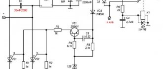
Diagram of a single-phase regulator relay for Viper Activ. DIY voltage regulator relay diagram
Those who own a motorcycle with six-volt electrical equipment know that the weakest point is charging. Either the battery suddenly runs low and starting the motorcycle is a problem, then the charge disappears somewhere and magically returns, sometimes you have to drive at night without a headlight so as not to completely drain the battery... The electronic relay-regulator is an analogue of the PP-1 voltage regulator and reverse current relay and will save you forever from these problems. No additional modifications to the motorcycle wiring diagram are required. The circuit contains a minimum of parts that have many analogues. The relay diagram is shown in the figure.
The topic is an exact copy of the message of the esteemed Skrut, published on the now deceased (1/3) - Russian.
Alpha moped starter relay
Domestic delivery service
Delivery in Moscow: tomorrow - from 400 rubles. Pickup: Novoryazanskoye sh., 3 - around the clock - free
Starter relay JH70,DELTA,ALPHA
you can purchase in our online store at the best price. It's always a pleasure to buy from us!
Add the item to your cart and place your order. After this, our manager will contact you and clarify all the details. Next, you pay for the order in any way convenient for you. You can receive the goods either by self-pickup or using a delivery service. Welcome to our stores, where you can also place an order and get all the necessary information!