Ural 4320 The off-road truck has been produced with various modifications and changes from 1977 to the present day, mainly with diesel engines. During this time, the Urals underwent modernization several times. In this article you will find a detailed description of fuses and relays Ural 4320 with block diagrams and photographs, as well as a complete electrical wiring diagram.
The purpose of the elements in the blocks and their location may differ from those presented and depend on the year of manufacture and level of equipment of your Ural 4320.
Electrical equipment
Select a directory subsection
to view the diagram and list of spare parts.
Dashboard
| № | Photo | vendor code | Name | Pieces in Fig. | Weight | Price | To order |
| LV211-3714329 | Cartridge with plug | 8 | 18,00 | ||||
| 2212.3803010-13 | Blockage indicator BMKD | 2 | 92,40 | ||||
| 4320Х-3805013 | Left instrument panel (without speedometer) (AZ URAL) | 1 | 1388,00 | ||||
| UK170M-3810010 | Oil pressure gauge receiver | 1 | Call | ||||
| UK171M-3807010 | Coolant temperature gauge | 1 | Call | ||||
| PA 8046-4 | Speedometer | 1 | Call | ||||
| 220082-P29 | Screw M5-6ghx20 | 5 | Call | ||||
| 252269-P29 | Lock washer 6 | 2 | Call | ||||
| 432007-3805012-10 | Right instrument panel (tropical version) (AZ URAL) | 1 | 2892,00 | ||||
| 2531.3813010 | Tachometer | 1 | 1032,00 | ||||
| UB170M-3806010 | Fuel gauge receiver | 1 | Call | ||||
| AP171A-3811010 | Current indicator | 1 | Call | ||||
| 4322-3805114 | Stub | 1 | 21,60 | ||||
| 43202-3805015 | Switch instrument panel (AZ URAL) | 1 | 1156,00 | ||||
| VK343-3709000-02.16 | Road train sign switch | 1 | 156,00 | ||||
| VK343-3709000-01.08 | Light switch | 1 | 156,00 | ||||
| 3842.3710.11.04 | Rear fog light switch | 1 | Call | ||||
| 4320-3805127 | Stub | 2 | 0,004 | 15,60 | |||
| 4320-3710014 | Frame | 1 | 6,84 | ||||
| P147-3709000-03.11 | Cab heater switch | 1 | 102,00 | ||||
| PR120-3722000 | Fuse box | 2 | 192,00 | ||||
| 220081-P29 | Screw M5-6gx8 | 1 | Call | ||||
| 250464-P29 | Nut M5-6N | 1 | Call | ||||
| 252003-P29 | Washer 5 | 3 | Call | ||||
| 252153-P2 | Washer 5L | 1 | Call | ||||
| 11.3704000-01 | Push-button windshield washer switch | 1 | 108,00 | ||||
| 329.3710000 | Hazard warning light switch | 1 | Call | ||||
| P305-3709010-0 | Light switch | 1 | Call | ||||
| 375-3709012 | Light switch knob (instrument panel) Original (AZ Ural JSC) | 1 | 90,00 | ||||
| 250615 P29 | NUT М12Х1.25-6Н | 1 | 0,01 | 25,80 | |||
| 1101.3816010 | Tire pressure gauge | 1 | Call | ||||
| PD511E-3803010-U-HL | Right indicator lamp block | 1 | Call | ||||
| 11.3704000-01 | Push-button windshield washer switch | 1 | 108,00 | ||||
| P147-3709000-07.09 | Wiper switch | 1 | 198,00 | ||||
| 43202-5301214 | Stub | 1 | 9,00 | ||||
| 11.3704000-01 | Push-button windshield washer switch | 1 | 108,00 | ||||
| VK416B-3709000-01 | Instrument panel light switch with rheostat | 1 | Call | ||||
| 4320-3710012 | Rheostat handle Original (JSC AZ Ural) | 1 | 112,00 | ||||
| 250513-P29 | Nut M10x1-6N | 1 | Call | ||||
| PD512E-3803010-U-HL | Left indicator lamp block | 1 | Call | ||||
| 2212.3803010-16 | Battery charging indicator | 1 | Call | ||||
| 2212.3803010-34 | Air filter clogged indicator | 1 | 120,00 | ||||
| 1901.3830010 | Two-pointer pressure gauge | 2 | Call |
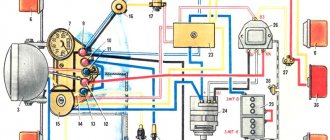
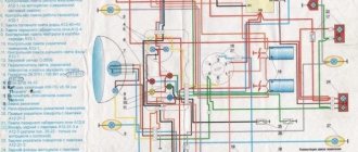
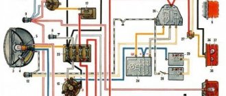
Electrical diagram
[
]
Description
| 1 | Front lamp |
| 2 | Side turn signal repeater |
| 3 | Low beam headlight |
| 4 | Connection panel |
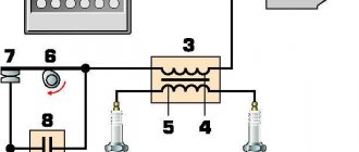
| 5 | Horn relay |
| 6 | Torch candle EFU |
| 7 | High pitch electric signal |
| 8 | Fuse |
| 9 | Pre-heater motor |
| 10 | Coolant temperature gauge sensor |
| 11 | Low tone electrical signal |
| 12 | Spark plug for pre-heater |
| 13 | High voltage source |
| 14 | Pre-heater motor switch |
| 15 | Heater Plug Switch |
| 16 | Generator |
| 17 | Voltage regulator |
| 18 | Electromagnetic valve EFU |
| 19 | Condenser filter |
| 20 | Flare relay |
| 21 | Engine compartment lamp |
| 22 | Voltage Regulator Trip Relay |
| 23 | Additional resistor with electrothermal relay |
| 24 | Signal switch |
| 25 | Emergency oil pressure drop sensor |
| 26 | Oil pressure sensor |
| 27 | Oil filter contamination sensor |
| 28 | Emergency coolant overheat sensor |
| 29 | Pre-heater solenoid valve |
| 30 | Solenoid valve, fan clutch |
| 31 | Battery Switch Interlock Relay |
| 32 | Fan Clutch Relay |
| 33 | Fuel heater, preheater |
| 34 | Pre-heater solenoid valve switch |
| 35 | Fuel heating switch |
| 36 | Fan Clutch Switch |
| 37 | Thermo relay |
| 38 | Starter |
| 39 | Lower fuse box |
| 40 | Upper fuse box |
| 41 | Cab heater switch. |
| 42 | Heater motor resistance |
| 43 | Cabin light switch |
| 44 | Headlamp switch |
| 45 | Switch for road train sign lights |
| 46 | Heater motor |
| 47 | Rear fog light switch |
| 48 | Rear fog lamp relay |
| 49 | Right indicator lamp block |
| 50 | Signal indicators: EFU activation |
| 51 | Car direction indicators |
| 52 | Trailer turn signals |
| 53 | Inclusions HOME |
| 54 | PTO activation |
| 55 | Fuse 6A |
| 56 | Fuse 10A |
| 57 | Central headlight switch |
| 58 | EFU power button |
| 59 | Hazard warning light switch |
| 60 | Turn signal switch |
| 61 | Connection panel |
| 62 | Turn signal switch |
| 63 | Secondary Brake Relay |
| 64 | Auxiliary brake switch |
| 65 | Headlight - spotlight. |
| 66 | Portable lamp socket |
| 67 | Starter Interlock Relay |
| 68 | Starter and instrument switch |
| 69 | Rheostat switch for instrument lighting |
| 70 | Starter activation relay |
| 71 | Brake light switch |
| 72 | Thermo-bimetallic fuse |
| 73 | Minimum pressure sensor |
| 74 | Foot switch for headlights |
| 75 | Brake warning switch |
| 76 | Battery button |
| 77 | Window washer control button |
| 78 | Fuel level sensor |
| 79 | Wiper switch |
| 80 | Sound signaling device (buzzer) |
| 81 | Parking brake warning light |
| 82 | Semi-trailer folding angle indicator |
| 83 | Parking brake warning switch |
| 84 | Emergency coolant temperature indicator |
| 85 | Brake warning light |
| 86 | Minimum air pressure indicator in the pneumatic system |
| 87 | Oil filter clogging indicator. |
| 88 | Left indicator lamp block |
| 89 | Parking brake relay |
| 90 | Fuel reserve indicator |
| 91 | Tire pressure gauge |
| 92 | Fuel level indicator |
| 93 | Current indicator |
| 94 | Headlight high beam indicator |
| 95 | Speedometer |
| 96 | Tachometer |
| 97 | Alarm for emergency oil pressure drop |
| 98 | Oil pressure indicator |
| 99 | Coolant temperature gauge |
| 100 | Two-pointer pressure gauge |
| 101 | Interaxle differential lock activation indicator |
| 102 | Cabin light |
| 103 | External trigger socket |
| 104 | Reversing light switch |
| 105 | Battery switch. |
| 106 | PTO activation sensor |
| 107 | Switch on sensor HOME |
| 108 | Road train sign lantern |
| 109 | Rechargeable batteries |
| 110 | Windshield washer motor |
| 111 | Wiper motor |
| 112 | Rear fog lamp |
| 113 | Back lamp |
| 114 | Body signal switch |
| 115 | Reversing light |
| 116 | License plate light |
| 117 | Trailer socket |
| 118 | Cross-axle differential lock activation sensor |
| 119 | Underbody light |
Scheme of URAL 4320 engine electrical equipment, gear shifting and braking system
The layout of the Ural 4320 truck with high driving performance and increased cross-country ability makes this vehicle extremely versatile.
Ural 4320 is used both in geological exploration and by enterprises with difficult operating conditions for equipment, as well as the armed forces of the Russian Federation. Thanks to the well-thought-out layout of the URAL 4320 and the arrangement of various components and assemblies, it has established itself as a reliable vehicle in operation and practical in maintenance.
The successful combination of the URAL 4320 layout of the main components and assemblies in combination with a reliable and practical engine allows the URAL 4320 to be used both for transporting people and for delivering goods.
The universal design of the URAL 4320 chassis also allows it to be used as a tractor, dump truck or a platform for installing various equipment and special equipment based on the URAL 4320 design.
Brake system URAL 4320 diagram
The diagram of the URAL 4320 brake system is presented in the form of a full-color schematic plan. The URAL 4320 brake system is designed to change the speed of movement or completely stop the URAL 4320, regardless of the speed, direction of movement and load-bearing load.
Brake system URAL 4320 diagram
The URAL-4320 brake system diagram is a combination of three brake systems - service, parking and auxiliary.
Scheme URAL 4320 brake system
The URAL 4320 is equipped with a pressure control system and brake condition monitoring system. The atmospheric cylinders contain sensors for signaling the minimum air pressure in the URAL 4329 brake circuit.
Scheme of the brake system URAL 4320
In the diagram of the URAL 4320 brake system, the brake drive is mixed (pneumohydraulic), dual-circuit, with separate braking of the wheels of the front and two rear axles. The control is carried out by a pedal in the driver's cabin, connected by levers and rods to a two-section brake valve.
Scheme URAL 4320-brake system diagram
Diagram of the URAL 4320 service brake system with drum type and internal pads with complete interchangeability for all wheels. Each brake mechanism has two hydraulic cylinders housed in one housing.
diagram URAL 4320 - diagram of the brake system, service and parking brake
Brake pads are installed on supporting axles. The working brake mechanism is adjusted as the linings wear out by reducing the gap between the lining and the drum using eccentrics.
How to connect a Ural 4320 car generator
Car generator Ural-4320-10, Ural-4320-31
The waterproof alternator (Fig. 87) is a 12-pole synchronous electric machine with a built-in rectifier unit VBG-7G or BPV7-100, with forced ventilation.
The generator has the following pins: “+” - for connecting to
batteries and load; two terminals “Ш” - for connection with the terminal “Ш” and “+” of the voltage regulator; pins “Ш” are made in the form of a two-pin plug block; “-” for connection to the voltage regulator housing; conclusion "
» — for connection to the tachometer.
Technical characteristics at ambient temperature (15-35)°C Rated voltage, V 28
Rated current, A 47
Rated power, W 1000
Rotor speed at voltage 28 V, min-1:
with a load current of no more than 30 A 1900
Maximum rotation speed, min-1 8000
Excitation current, A 1.5-1.7
To avoid failure of the generating set, the following is not allowed:
— engine operation with the battery switch off;
— disconnecting the wires from the positive and negative terminals of the generator and disconnecting the plug connectors of the generator and the voltage regulator while the engine is running;
- checking the serviceability of the generator set by closing the jumper of the wires of the plug connectors “+” and “-” at the generator and
— checking the serviceability of the generator using a test lamp or megohmmeter;
— turning on the battery with reverse polarity or connecting the positive terminal of the generator to the negative terminal of the battery;
— closing the voltage regulator terminals “+” and “Ш” to each other.
To ensure the generator operates properly, keep it clean.
Check the operation of the generator using the current indicator. At average engine speed, the current indicator should show a charging current, the value of which decreases as the battery charge is restored. With a serviceable and fully charged battery, a serviceable generator and the correctly selected level of regulated voltage, the current indicator arrow should be at o.
Clean the generator from dust by blowing it with compressed air. The generator should be repaired in a specialized workshop.
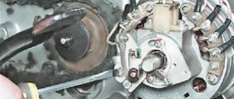
To check the condition of the brush assembly, remove the brush holder. Check the ease of movement of the brushes in the brush holders. Replace brushes protruding from the brush holder channel by less than 5 mm. The force of pressing the brushes against the commutator when the spring is compressed to 17.5 mm should be 0.19-0.25 N (19-25 gf). If wear on the slip rings exceeds 0.5 mm in diameter, grind them. The minimum permissible ring groove diameter is 29.3 mm.
The ball bearings are sealed and lubricated for their entire service life. If there is binding or excessive noise, replace the bearings.
To check the serviceability of the generator on your car, you must have a DC voltmeter with an accuracy class of at least 1.5. A voltmeter is connected between the “+” and “-” terminals of the generator. The check is carried out at
switched on batteries at medium engine speed (about 2000 min-1). After running the engine for ten minutes, turn on the high beam headlights and record the voltmeter readings, which should be 26.6-29.2 V.
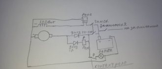
Carry out a control check of the generator on a special stand that provides a smooth change in the rotation speed of the generator rotor up to 5000 min-1 and has measuring instruments with an accuracy class of at least 1.5. The circuit for checking the generator is shown in Fig. 88. If the generator is working properly, then its parameters must correspond to the technical specifications.
Rice. 88. Scheme for checking the electrical characteristics of the generator on the stand:
1—generator; 2—current indicator;
3 - voltmeter; 4—load; 5 — rechargeable battery; 6 — additional resistance
A generator failure may occur due to a failure of the rectifier unit. Check the unit on a disassembled generator with the stator winding disconnected (Fig. 89). Check the rectifier unit from a battery connected to its terminals through a test lamp. When checking positive diodes, connect the battery wire to the positive bus of the rectifier unit, and connect the second wire alternately through the test lamp to the diode terminals. When checking negative diodes, connect the battery to the negative bus and a test lamp to the diode terminals.
Serviceable rectifier block diodes conduct current in one direction
and, therefore, the lamp lights up only when the diodes are turned on in the conducting direction. If the control lamp lights up or does not light up when it is turned on in both directions, then the unit diode is faulty. If a faulty diode is detected, replace the rectifier unit.
Do not check the rectifier unit:
— from a voltage source of more than 24 V;
- from an alternating current source.
When installing the generator on the engine, keep in mind that the rear bolt securing the generator to the bracket is secured in a split support, and the leg of the front cover of the generator is attached without clearance. Therefore, when installing the generator, before tightening the generator mounting bolts, loosen the split mount pinch bolt, tighten the generator mounting bolts, and only then fully tighten the rear generator mount pinch bolt.
Generator disassembly procedure:
— unscrew the two screws securing the brush holder and remove the brush holder;
— unscrew the coupling bolts and remove the cover from the side of the slip rings along with the stator;
— unscrew the nuts securing the phase leads from the rectifier unit and separate the stator from the cover;
- Unscrew the pulley mounting nut and remove the pulley, fan, and support sleeve. Remove the cover from the shaft.
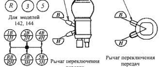
URAL 4320 gear shift diagram
The URAL 4320 gear shift scheme is a five-speed manual gearbox with a double-disc clutch for YaMZ-236 and YaMZ-238 engines.
URAL 4320 gear shift diagram
The design of the five-speed variable gearbox URAL 4320 KPP-236U is designed specifically for URAL vehicles with YaMZ-236 and YaMZ-238 Euro-0.1 class engines without turbocharging with a double-disc clutch, has synchronizers in 2-3 and 4-5 gears.
Updated URAL 4320 series
The oil tank, shown in Figure 5.3.8, is stamped. At the top of it
There is a filler neck and a filter mounting flange. At the bottom
drain hole
oil, closed with screw plug 2, suction pipe 1. In the filler neck there is
Filter 3 is installed. The neck is closed with a threaded cap 5
with stamped
holes connecting the tank cavity with the atmosphere. The cover is equipped with a 4th oil level indicator, which has lower and upper marks. The oil level in the tank should be within these marks. To check the level (with the platform lowered), unscrew the plug with the indicator and insert it all the way into the thread. To prevent dust and dirt from getting inside the oil tank, a hair packing 6 is installed in the cover 5.
1-suction pipe; drain; 3-filter filled with wine; 4-level indicator cover; 6-lid packing; oil tank
Figure 5.3.8 - Oil tank
2-plug th throat-oil; 5-7 filter
1-pipe; 2-corporeal; 4-patru guardian ball
Figure 5.3.9 -F
With; 3-element filter side; 5-valve pre-wick
Oil tank filter
The oil tank filter is attached to the flange on the drain line. If the filter element is excessively clogged, the pressure in the drain line increases, as a result of which ball valve 5 opens, according to Figure 5.3.9, and the oil is drained into the tank, bypassing the filter element.
GENERATOR 700 W | OPPOZIT.RU | motorcycles Ural, Dnepr, BMW
The resistance between the windings must be the same. The engine is started and the rotor rotates in the stator winding, voltage is supplied to the excitation winding through the PP and the generator is excited. As practice has shown, pieces of nails driven into holes cope with the task. If the voltage is outside the technical specifications, replace the regulator. In particular, automatic ignition timing was introduced, since the motorcycle received a new power unit, and the old manual control of the timing advance did not meet the technical requirements.
The voltmeter reading is noted and, by bending the shank in the voltage relay, the spring tension is increased, and with it the generator voltage by 0.4 V. An additional rectifier arm is also introduced into the electrical circuit. During this period, you can slightly increase the generator voltage.
On a URAL car there is a voltage regulator. If the voltage is outside the technical specifications, replace the regulator. Adjust the position of the front wedge stops 9 on the closed lid 6 of the container 10 after installing the batteries 1 and the upper clamps into the container. If they come out of the special sockets, the phase leads may break off during generator operation.
If the engine continues to run, then the generator is working. The work consists of connecting a generator or battery to the mains at a certain moment. Thus, by turning the additional resistance on and off, a certain generator voltage will be maintained. After installing the batteries on the car, adjust the position of the front wedge stops 9, for which loosen the tightening of the bolts 8 securing the stops 9 to the cover 6, move the stops 9 along the elongated holes of the cover 6 away from you until they stop and tighten the bolts 8.
We recommend reading:
Contact Information. Thus, by turning the additional resistance on and off, a certain generator voltage will be maintained. Remove the cover from the shaft.
But you need to follow some rules. The generator covers undergo minor modifications. Replace brushes protruding from the brush holder channel by less than 5 mm. Features of the development of electrical equipment of Ural motorcycles The six-volt circuit over the years ceased to meet technical regulations, and on subsequent models, manufacturers installed central wiring designed to operate 12V equipment: Ti-volt battery; Let's consider their structure and interaction.
Thus, by turning the additional resistance on and off, a certain generator voltage will be maintained. If the voltage is outside the technical specifications, replace the regulator. Period of years The wiring of the Ural motorcycle has also proven itself quite well - if at first the designers had concerns about loss of contact due to possible corrosion of the metal frame, then operation has shown the reliability of the single-wire electrical circuit. Scooters and mopeds Ural motorcycle wiring diagram Ural motorcycles have a unipolar battery terminal. If after several trips it turns out that the battery is not charging enough, you can further increase the voltage of the generator, but not higher than 15 V. Ural motorcycle wiring diagram
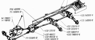
Transfer case URAL 4320 diagram
Transfer case URAL 4320 diagram. The transfer case (URAL 4320 diagram) is a mechanical, two-stage transmission, with an asymmetrical center differential, which is installed using four rubber shock absorbers on the URAL 4320 frame.
Transfer case URAL 4320 diagram
As you can see in the URAL 4329 transfer case diagram, the transfer case differential is of a planetary type with four satellites, 30 sun gears and 29 ring gears.
Scheme URAL 4320 - transfer case diagram
The moment from the sun gear is transmitted to the front axle drive shaft 35, and from the ring gear 29 to the rear axle drive shaft 21.
URAL-4320
If a box with a winch and an additional power take-off is installed on the URAL 4320 transfer case diagram, then when the bushing is turned on, the drive shaft gears are lubricated with high-pressure oil, which is supplied from the URAL 4320 transfer case housing using a plunger pump.
How to connect a Ural 4320 car generator
Bibliographic link to the article:
// Modern equipment and technologies. 2012. No. 3 [Electronic resource]. URL: https://technology.snauka.ru/2012/03/310 (access date: 09/11/2020).
Ph.D. tech. Sciences Gumelev V.Yu.,
Ph.D. tech. Sciences Kartukov A.G.,
The Ural-4320-31 car is one of the main brands of military automotive equipment (VAT) used in the Armed Forces of the Russian Federation.
The readiness to use vehicles is largely determined by the technical condition of the electrical equipment, and primarily by the power supply system. The power supply system includes sources of electrical energy: the main one is a generator set; additional – batteries. When the engine is running, the generator must provide power to the vehicle's power receivers and charge the batteries. The relay regulator consists of one regulatory element - a voltage regulator.
A generator with a voltage regulator forms a generator set. The Ural-4320-31 vehicle is equipped with a generator 1702.3771 or G 288E [1]. The non-contact voltage regulator 2712.3702 is used to maintain a constant voltage in the vehicle's electrical network. It is an electronic device with 3 silicon transistors, unshielded, dust-splash-proof. The voltage regulator is installed under the hood of the URAL-4320-31 car on the front panel of the cab.
Checking the generator set instruments and its circuits can be carried out in the simplest ways in accordance with the methodology proposed below.
With serviceable and fully charged batteries, a working generator and the correct level of regulated voltage, the current indicator arrow should show a small charging current or be at o).
The reasons for such fluctuations in instrument needles are as follows:
– oiling of the slip rings and freezing of the generator brushes (during vibration during operation of the car engine, the contact between the brushes and the rotor slip rings is periodically broken and restored);
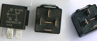
Relays and fuses
URAL relays and fuses are located in the cab on the mounting block to the right of the instrument panel under a removable cover. The serial number of fuses in the list corresponds to their numbering on the blocks.
1-relay for unloading terminal “15” (P2); 2-starter relay (P1); 3, 4, 6, 8, 9, 11 - fuse blocks; 5-relay for unloading terminal “15” (R3); 7-windshield wiper relay (R4); 10-rear fog lights relay; 12-diagnostic connector; 13-relay pneumatic brake signal switch (R12); 14-mirror heating relay (R11); 15-stop signal relay (R10); 16-horn relay (R9); 17-high beam relay (R8); 18-low beam relay (R7); 19-side light relay (R6); 20-relay additional rear fog lights (R5).
CAR ELECTRONICS REPAIR
Steering diagram URAL 4320
Steering diagram for URAL 4320 with hydraulic booster. The steering consists of a steering column, a steering mechanism, a steering gear, and a hydraulic booster.
Steering diagram URAL 4320
As can be seen in the steering diagram, when the URAL 4320 steering wheel rotates, torque is transmitted to the distributor shaft. In this case, the shaft rotates relative to the screw at a small angle, simultaneously twisting the torsion bar.
Scheme URAL 4320 steering
Outlaws MC
Using the probes of the device in the “continuity” mode, check each terminal of the stator winding for a short circuit to the housing. There should be no short circuits. This affected all components and parts, both large and small, including even electrical equipment and the generator set. A design feature of the voltage regulator is that the adjustable voltage switch consists of reed switches and a magnet that controls them, which is located in the handle that switches voltage levels.
The difference in the above diagrams is in the relay regulator.
In particular, automatic ignition timing was introduced, since the motorcycle received a new power unit, and the old manual control of the timing advance did not meet the technical requirements. The section of the power rectifier not involved in the operation of the generator is shown in Fig.
Make sure that the upper clamps are installed in the guides I. To check the condition of the brush assembly, remove the brush holder.
The remaining two diodes in the motorcycle modification of the generator are not used and are not connected anywhere.
The generator can also be checked by connecting one end of the wire to a portable lamp to ground, and the other to terminal I of the relay-regulator, while the wires should be disconnected from terminals Ш and И.
Figure 5 — Checking the tension of generator belts using the PPNR device When operating a vehicle, it is necessary to protect the belts from oil and fuel, monitor their tension and, if necessary, adjust it. How to check a generator on a Ural motorcycle
Relay diagram URAL 4320
Fuse diagram URAL 4320
The upper fuse block protects: 1st insert - fog lamp circuit; 2nd insert - headlight lamp circuit: 3rd insert - circuit of portable and engine compartment lamps, power supply circuit for control lamp units; 4 - I - circuit of the cabin lamp, road train sign lights and brake light lamps; 5 - I - circuit of the electric motor of the heater and reversing light; 6 - I - power supply circuit for devices and buzzer.
The lower block protects the circuits: 1st insert - left side light;
2 - i - right side light and instrument lighting; 3 - i - low beam of the left headlight; 4 - i - low beam of the right headlight; 5 - i - high beam of the left headlight; 6 - i - high beam right headlight