Permanent all-wheel drive with a transfer case, and not some kind of clutch. The generator is assembled in the reverse order. Approximately, the procedure for connecting is as follows: Find the wiring diagram for your motorcycle model. Features of the development of electrical equipment of Ural motorcycles The six-volt circuit over the years ceased to meet technical regulations, and on subsequent models, manufacturers installed central wiring designed to operate 12V equipment: Ti-volt battery; VEHICLE ELECTRICAL EQUIPMENT.
The diameter of one cylinder is 75 mm, the piston stroke is 77 mm.
You need to avoid getting confused which wire goes to the right and which to the left; try marking them for yourself.
It became - when the mass is turned on, the toad and magnetization genes are energized, and the feet work like a machine, without the 3Z, and with the 3Z everything else works as expected.
Remove the cover from the shaft.
If the wires are not disconnected from the battery, lift the battery handles 1 together with the wires and, holding them, remove the stop 4; remove the upper clamps 13 from the container
Green Ural and black candles. We are looking for the cause of the malfunction.
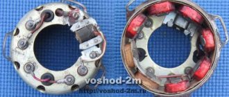
Generator Voskhod G-427
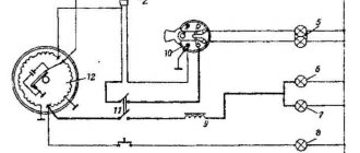
Generator G-427 alternating current with excitation from a permanent magnet with an inductive sensor of the electronic ignition system. In the grooves of the stator, made of stamped electrical steel plates, eight coils are placed, which form four independent circuits: - power supply to the ignition storage capacitor; — lighting and sound signal; — direction indicators; — braking signal.
Voltage regulation in the circuits of lighting loads is carried out according to the principle of parametric regulation, i.e. The winding data of the generator are selected in such a way that as the rotor speed increases, the voltage at the generator terminals changes within certain limits for a certain load. Attaching the generator stator to the engine crankcase provides adjustment of the ignition timing.
On the generator stator cover there are terminals: - charging coils of the power supply circuit of the Voskhod ignition storage capacitor; — direction indicators; — brake signal; — lighting; — sensor.
Which are marked accordingly: <<З>>, <<У>>, <<Т>>, <<О>> and <<Д>>.
The sensor is mounted on the generator stator cover using screws.
Generator rotor
The generator rotor with the sensor rotor located on it is mounted on the right axle axis of the engine crankshaft with a bolt and is secured against rotation by a key.
Return to content
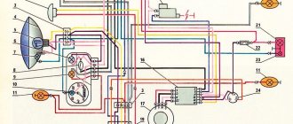
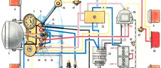
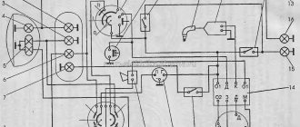
Electrical diagram
After all, the ignition system of Soviet bikes is very simple, which allows attackers to steal a bike without any problems.
After installing the batteries on the car, adjust the position of the front wedge stops 9, for which loosen the tightening of the bolts 8 securing the stops 9 to the cover 6, move the stops 9 along the elongated holes of the cover 6 away from you until they stop and tighten the bolts 8. Do not check the rectifier unit: from the voltage source more than 24 V; from an AC source. Video instructions: wiring diagram for the ignition switch on a Ural motorcycle. Interesting facts about Isuzu cars.
It’s easy to get confused in a large number of wires and terminals, so you need to call them one by one. It is recommended to start with the relay. For reference: Over the two decades since its release, the motorcycle has proven its worth as a mobile vehicle, most suitable for use in off-road and urban environments. In just one year, the Irbit Motor Plant produced almost 10 Ural motorcycles
In just one year, the Irbit Motorcycle Plant produced almost 10 Ural motorcycles. When connecting the dimensions, it is necessary to include a fuse in the circuit. The front wedge stops 9 are adjustable and secured to the lid of the container with bolts 8. Remove the lid from the shaft.
Solder the end of the wire to the desired terminal. In this simple way you can set the ignition switch of a Ural motorcycle, the circuit of which is slightly different from other Soviet units.
It was possible to plug in a relay, unload the lock, but I was too lazy to go to the market for the relay, and I decided to make another fifth fuse separately, power it from the plus, which comes from the gene to the lock, and after the fuse - the original wire that goes to the RR and a brake pad. The regulator is shipped from the factory with a medium setting level. There are enough dynamics. It should be no more than 0.5 mm.
Apply current to the contacts alternately. To service batteries on a vehicle, loosen the wires and jumpers to the batteries; remove the front stop 4 from the container 10, lifting one end of the stop 4 until it comes out from behind the amplifier 5 of the container. To remove the batteries from the car, slide one battery onto the bracket 3 and remove it from the car. Motorcycle Ural. #51. Connecting the JAWA ignition switch.
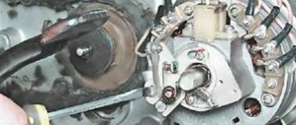
Caring for a sunrise motorcycle generator - how to remove, what to check and install correctly
Generator maintenance mainly comes down to tightening the threaded fasteners of the generator stator and rotor, as well as the wire terminals.
In order to remove the generator, you must:
- disconnect the wires of the ignition circuit, sensor, brake light and direction indicators from the generator terminals;
- unscrew the three screws securing the stator to the crankcase and remove the stator;
- Unscrew the bolt securing the generator rotor and, with light, careful blows of a wooden hammer on opposite sides of the rotor, remove it from the trunnion and remove the key.
Checking the removed parts
After removing the generator stator and rotor, wash the parts with clean gasoline and carefully inspect them. Disassemble the wire fastening terminals on the stator. Wipe dry all insulating parts of the terminals.
Generator installation
Installation is carried out in the reverse order, in this case it is necessary:
- check the runout of the generator rotor, which should be no more than 0.1 mm with the bolt secured;
- tighten the generator stator without distortions, ensuring a tight fit to all three supports;
- install the ignition correctly;
- The generator wires must be securely fastened and well insulated from each other.
Return to content
New blog posts
The wiring diagram for the ignition switch of a Ural motorcycle is quite simple; any beginner can handle it if desired. Heating - loss of voltage, loss of voltage - worse than a spark; then there was still a cam. Make sure that the upper clamps are installed in the guides I. Alternately apply current to the contacts.
Review from a car owner named Istoma: Handling - it runs like it’s on rails, brakes well and doesn’t roll.
Therefore, when installing the generator, before tightening the generator mounting bolts, loosen the split mount pinch bolt, tighten the generator mounting bolts, and only then fully tighten the rear generator mount pinch bolt. Variety of circuits Wiring often deteriorates when exposed to the external environment and you have to buy a new one.
Connect one wire of the control lamp to the low voltage terminal, the second to ground.
Good light. It was created for cars, but is also well suited for motorcycles; if you know someone who has such a unit, borrow it and make your life much easier. Preparing dry-charged batteries for operation The procedure for preparing batteries to bring them into working condition: remove the protective casing and cover, clean the batteries from dust, and the terminal bolts from grease; Unscrew the plugs from the filler holes, remove the sealing gaskets and clean the ventilation holes in the plugs. Newer models have many upgraded parts that are significantly different from older versions.
Scheme for checking the rectifier unit: a - checking positive diodes; I - diodes are turned on in a non-conducting direction; II - diodes are turned on in the conductive direction. Serviceable diodes of the rectifier unit conduct current in one direction and, therefore, the lamp lights up only when the diodes are turned on in the conductive direction. Solder the end of the wire to the desired terminal. Motorcycle Ural. Wiring. Part 1.
More on the topic: Connection diagram for a two-key switch
Ignition adjustment Voskhod
The ignition timing is set by turning the generator stator after first loosening the three screws securing the stator to the crankcase. For normal engine operation, it is necessary that the moment of spark formation (on the generator, this moment is determined by the coincidence of the sensor rotor groove with the protrusion on the sensor coil frame. Fig.) coincides with the moment when the piston does not reach the top dead center of 2.5-3.0 mm (at running the engine on gasoline with an octane rating of 92).
The gap between the rotor and the core of the sensor coil should be within 0.3±0.05mm.
The gap should be set as follows:
- loosen the screws securing the sensor stator to the generator stator cover;
- By moving the sensor stator in the grooves of the generator stator cover, set the required gap, and then tighten the fastening screws.
For more accurate ignition installation, it is recommended to determine the piston position with the cylinder head removed.
Return to content
Switch Voskhod - electronic KET-1
The electronic switch KET-1 is designed to work in the ignition system complete with the G-427 generator and the B-300B high-voltage transformer. Allows you to obtain a secondary voltage of up to 18 kV, at a generator rotor speed of 250 to 7500 rpm. The switch is installed in the right toolbox. The base of the commutator is connected to the ground of the motorcycle. If the switch fails, it can be disassembled and repaired
The electronic switch has three output terminals with letter markings on the body <<Г>>, <<К>> and <<Д>>. The ground terminal is the base of the switch.
Maintaining the switch during operation comes down mainly to tightening the threaded connections, while avoiding stripping the threads. It is necessary to protect the switch from moisture getting inside it and onto the terminals from sudden shocks and exposure to high temperatures. You should also systematically check the reliability of the electrical connection of the switch base with << ground >>, because If this condition is violated, sparking on the spark plug stops.
Return to content
Ignition switch Voskhod - central switch
Switch 124005490201 is used as a central software switch that provides the necessary switching of lighting equipment on a motorcycle. The switch has three operating positions <<0>>, <<1>>, <<2>> in accordance with the following operating modes:
- in position <<0>> - the generator sensor circuit is shorted to ground, which ensures the engine stops.
- in position <<1>> (driving during the day) - the ignition circuit is turned on, the direction indicator circuit operates (when the direction indicator switch is on) and the brake signal circuit (when the brake pedal is pressed);
- in position <<2>> (driving at night), two circuits are switched on:
- a) a circuit of speedometer backlight lamps, license plate lighting and city driving (through a throttle, which serves as a device that complements the parametric control of the generator);
- b) headlight lamp circuit A6-32+32 (via the light switch on the steering wheel).
Caring for the central switch comes down to periodically checking the reliability of the switch in the headlight and cleaning the moving and fixed contacts from dust and dirt by washing them in gasoline.
Relay operating principle:
The correct diagram, which shows the meaning of using a relay, is presented below. By controlling the electromagnetic relay coil through key SA1 with low voltage and current, the relay closes a pair of contacts K1.1 and switches higher voltage and current to lamp HL1. Why is this necessary? It would seem, why not just use SA1 and a 12 volt battery, simply supplying current through it. Yes, everything is simple, in this way low-current circuits control power ones, while preserving the contacts of the SA1 switches from burning out and saving the power parts of the circuits (large cross-section wires, overall dimensions of products), the SA1 switch is not designed for power loads and higher voltages and is thus decoupled from the power part.
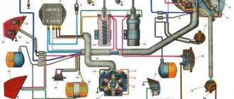
Now let's move on to the simplest circuit for a motorcycle, which you can make with your own hands. But first we need this very scheme! First, let's divide the motorcycle's electrical wiring into several nodes and describe them in a conventional graphic diagram. This diagram gives clarity to the whole picture. The blocks themselves are easier to consider separately.
Here is a graphical diagram of the components of the electrical circuit of the motorcycle as a whole. Let's look at the meaning and functions of blocks.
Blocks:
— Generator. — Rectifier block. — Voltage stabilizer (Regulator). - Power supply. — Fuse block. — Ignition control unit. — Electrical diagram of consumers (starter, light, repeaters, etc.)
A generator is a machine that converts mechanical energy into electrical energy. The generator is connected to the engine through gears, belts and other connections. During operation, the engine simultaneously rotates the generator, which in turn produces electrical energy. The generator can be either direct or alternating current. We will consider an alternating current generator.
Graph of alternating voltage versus engine speed. In simple terms, the faster the engine rotates, the more energy the generator produces.
Since the on-board network is designed to operate with direct current at a voltage of 12V, we need to rectify the current and stabilize the voltage.
The rectifier unit is a converter of the input electrical current AC to DC. Performed on semiconductor diodes.
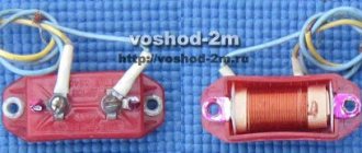
Technologies do not stand still and in the photo above, on the left, there is a so-called “horseshoe” diode assembly used in generators, and on the right is a diode assembly of the same principle, but much smaller in size. Both can be used in circuits.
Voltage stabilizer (regulator) is an electromechanical or electrical semiconductor device that allows you to change the output voltage. The simplest meaning of the regulator is that while the voltage does not exceed 14V in the network, the regulator supplies voltage to the excitation winding of the generator; as soon as the speed increases, at which the voltage is above 14V, the regulator turns off the excitation winding and the generator stops generating energy and essentially spins in single. It is most likely not correct to call this system a voltage stabilizer, since it is not a stabilizer, but the point is to provide more or less stable on-board power.
In the photo above there is a relay-regulator, different in size and design. The first is electromechanical and large, the last two are more modern and electronic, made on a semiconductor element base.
The operation of the components: Generator, Rectifier, Relay-regulator was described in more detail in the article Restoration, testing, connection of the G424 generator
Power source - DC battery. First of all, it is required for the initial start of the engine and maintaining the on-board network within 12V at a time when the generator does not provide the required voltage during rotation. In fact, a running engine will work without a battery. While the generator provides the network with the necessary energy, the battery is charged.
Fuse box - provides protection for electrical circuits from short circuits. The essence of this block is a set of fuse links designed for a certain current. If the fuse is below the power consumption rating, it will blow and disconnect a section of the circuit from the on-board circuit. Therefore, the fuse must have a rating greater than the current consumed by the circuit in normal operation, and the rating must be such that in the event of a short circuit the fuse will burn out before the wiring.
You can also look at the fuse box here Fuse box
Well, now, let's look at the electrical circuit of consumers in more detail.
Switch P-200
Light switch with horn button (located on the left side of the steering wheel). To switch the low and high beam circuit, a P-200 type switch is used with a built-in push-button horn switch for three operating positions: neutral - the headlight lamp is off; far right - low beam is on; far left - high beam is on.
The horn button has a movable contact connected to ground and a fixed contact connected to one of the wires coming from the horn terminal. When you press the button, the contacts close and the signal circuit is completed.
Return to content