Appearing in the pre-war years, the Ural motorcycle became the main heavy motorcycle of the USSR for many decades. Moreover, the Irbit Motorcycle Plant continues to produce modifications of the Ural motorcycle in 2013. But in the last decade, they abandoned the independent production of component parts, leaving behind the final assembly from purchased elements.
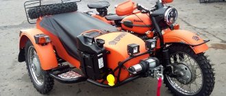
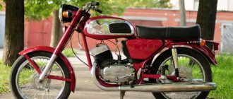
Photo of the Ural M-67 motorcycle, model 1976.
For reference: unfortunately, the decrease in output led to the fact that the selling price in the Urals increased significantly, which affected the number of sales. They have dropped noticeably, and today the Irbit Motorcycle Plant produces motorcycles only to order.
Transmission
Until 1963, the K 750 was equipped with an M-72 motorcycle gearbox.
Later, changes were made to the design of the shift clutches, the secondary shaft and its gears. Splines are cut on the secondary shaft, along the outer diameter of which the gears can rotate freely.
Between the gears of the first and second gears, as well as the third and fourth gears, fixed bushings are installed on the splines of the secondary shaft. These bushings also have external splines along which the movable couplings move. The internal surfaces of the couplings have small splines for engagement with the splines of the gears of the corresponding gears.
Cardan and main gears serve to transmit torque from the secondary shaft of the gearbox to the drive wheel.
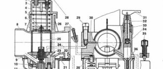
The cardan transmission consists of a cardan shaft 18, an elastic coupling 16, a cross 14 and a cardan fork 21, a casing 20 and an o-ring 19.
The cardan shaft receives rotation from the secondary shaft of the gearbox through an elastic coupling consisting of two steel disks 17 connected by pins to an elastic rubber coupling.
One of the disks fits onto the driveshaft splines, and the other is installed on the end of the transmission output shaft.
The drive gear of the main gear receives rotation from the propeller shaft through a cardan joint consisting of a crosspiece and two forks with needle bearings 13. The bearings are lubricated through a grease nipple 15.
The main gear consists of the following main parts: a crankcase with a cover 26, a driving gear 24 and a driven gear 29, and a driven gear hub 5.
All the main gear parts are located in the crankcase, which is also an oil reservoir, a brake housing and a support for the right end of the wheel axle.
Gasket 30 is installed between the crankcase and the cover.
The gears are made with spiral teeth.
The drive rotates on a ball bearing 23 and a needle bearing 8.
The driven gear is connected with bolts to the hub, which rotates on a ball bearing 25 and on bronze liners 4.
Rotation of the drive wheel hub is transmitted through the internal gearing formed by hub 5 and the hub of the driven wheel gear.
Oil is poured into the main gear crankcase through a hole closed by plug 1. To prevent oil from leaking out of the crankcase, there are oil seals 11 and 7, secured with a cap 6.
GENERATOR 700 W | OPPOZIT.RU | motorcycles Ural, Dnepr, BMW
The resistance between the windings must be the same. The engine is started and the rotor rotates in the stator winding, voltage is supplied to the excitation winding through the PP and the generator is excited. As practice has shown, pieces of nails driven into holes cope with the task. If the voltage is outside the technical specifications, replace the regulator. In particular, automatic ignition timing was introduced, since the motorcycle received a new power unit, and the old manual control of the timing advance did not meet the technical requirements.
The voltmeter reading is noted and, by bending the shank in the voltage relay, the spring tension is increased, and with it the generator voltage by 0.4 V. An additional rectifier arm is also introduced into the electrical circuit. During this period, you can slightly increase the generator voltage.
On a URAL car there is a voltage regulator. If the voltage is outside the technical specifications, replace the regulator. Adjust the position of the front wedge stops 9 on the closed lid 6 of the container 10 after installing the batteries 1 and the upper clamps into the container. If they come out of the special sockets, the phase leads may break off during generator operation.
If the engine continues to run, then the generator is working. The work consists of connecting a generator or battery to the mains at a certain moment. Thus, by turning the additional resistance on and off, a certain generator voltage will be maintained. After installing the batteries on the car, adjust the position of the front wedge stops 9, for which loosen the tightening of the bolts 8 securing the stops 9 to the cover 6, move the stops 9 along the elongated holes of the cover 6 away from you until they stop and tighten the bolts 8.
We recommend reading:
Contact Information.
Thus, by turning the additional resistance on and off, a certain generator voltage will be maintained. Remove the cover from the shaft. But you need to follow some rules. The generator covers undergo minor modifications. Replace brushes protruding from the brush holder channel by less than 5 mm. Features of the development of electrical equipment of Ural motorcycles The six-volt circuit over the years ceased to meet technical regulations, and on subsequent models, manufacturers installed central wiring designed to operate 12V equipment: Ti-volt battery; Let's consider their structure and interaction.
Thus, by turning the additional resistance on and off, a certain generator voltage will be maintained. If the voltage is outside the technical specifications, replace the regulator. Period of years The wiring of the Ural motorcycle has also proven itself quite well - if at first the designers had concerns about loss of contact due to possible corrosion of the metal frame, then operation has shown the reliability of the single-wire electrical circuit. Scooters and mopeds Ural motorcycle wiring diagram Ural motorcycles have a unipolar battery terminal. If after several trips it turns out that the battery is not charging enough, you can further increase the voltage of the generator, but not higher than 15 V. Ural motorcycle wiring diagram
https://youtube.com/watch?v=qjV0L-VZlQ8
Installing a car generator through a pulley with an adapter in place of the generator.
This path is taken for a number of reasons. A) Someone is not satisfied with the power of the already archaic 12V generator G424 - 150 W. The Vladikavkaz plant no longer produces them, and the quality of Chinese manufacturers leaves much to be desired. B) Increasing the power output and charging the battery from idle. This method has one significant drawback, the increased load on the timing mechanisms. An alternative to this method is the following
Electrical diagram
The electrical circuit in the Urals, unlike the BMW, is built on a single-wire version. The disadvantage is the metal frame; the voltage is 12 volts. The main advantage of the Ural motorcycle is its simplicity and ease of repair. You can even repair your motorcycle on the road. The ability to independently adjust the electrical system according to the wiring diagram makes it simply irreplaceable.
Each model can literally be remade to suit you, configure and clean the power system, adjust the wiring and, in case of breakdown, replace the damaged parts yourself with new ones.
The electrical circuit diagram of the Ural motorcycle includes:
- Side light lamp;
- Spark plug;
- Rotor;
- Brake signal;
- Relay regulator;
- Rotor breaker;
- Capacitors;
- Ignition distributors;
- The ignition switch itself and the key to it;
- Primary and secondary windings in a coil;
- The ignition coil itself;
- Accumulator battery;
- Fuse box;
- Generator;
These are the main points of the electrical equipment diagram, changing and adding new points depending on the configuration of the model. Newer models have many upgraded parts that are significantly different from older versions. However, single-pole terminals are used throughout, reducing power consumption and requiring less wiring. Unipolar terminals are a point due to which the motorcycle breaks down much less.
Variety of schemes
Wiring often deteriorates when exposed to the external environment and you have to buy a new one. How to connect new wiring and understand it? The main connection problem in the Urals is the display of side lights, high and low beams, turn signals, and other light bulbs on the dashboard. It’s easy to get confused in a large number of wires and terminals, so you need to call them one by one.
Approximately, the procedure for connecting is as follows:
- Find the wiring diagram for your motorcycle model.
- Looking at the diagram, select the first terminal.
- It is recommended to start with the relay.
- Using the diagram, look at the direction of the wire and where exactly it should be connected.
- Solder the end of the wire to the desired terminal.
When connecting dimensions, it is necessary to include a fuse in the circuit. And the high and low beams are in any case soldered to the switch on the central contact (combination). When connecting turn signals, one wire goes from the center contact with the switches to the relay to receive power.
You need to avoid getting confused which wire goes to the right and which to the left; try marking them for yourself.
For ease of working with electronics and settings, there is a car strobe light. It was created for cars, but is also well suited for motorcycles; if you know someone who has such a unit, borrow it and make your life much easier. There are many circuits for wiring a motorcycle, each with its own characteristics. It is necessary to initially decide on a scheme, and then simply act step by step.
Amazingly, “born” even before the war, the Ural motorcycle secured its status as the leader of heavy motorcycle construction in the Soviet Union for many decades. Even in the 21st century, the Irbit Motorcycle Plant, which is inextricably linked with this brand, still produces now homologated “grandchildren” of the legendary motorcycle.
Photo from the Irbit State Motorcycle Museum - Ural M-72 model 1952
To be fair, it should be noted that today’s assembly is made mostly from purchased parts, whereas in the years of the Union we were talking about a full production cycle. This could not but affect the volumes, since the price of motorcycles from the Irbit plant increased significantly.
Ural motorcycle wiring diagram: features of electrical equipment development
Did you like the article? Follow our channel for new ideas of useful car tips. Subscribe to us in Yandex.Zen. Subscribe.
Appearing in the pre-war years, the Ural motorcycle became the main heavy motorcycle of the USSR for many decades. Moreover, the Irbit Motorcycle Plant continues to produce modifications of the Ural motorcycle in 2013. But in the last decade, they abandoned the independent production of component parts, leaving behind the final assembly from purchased elements.
For reference: unfortunately, the decrease in output led to the fact that the selling price in the Urals increased significantly, which affected the number of sales. They have dropped noticeably, and today the Irbit Motorcycle Plant produces motorcycles only to order.
Chassis
The M62 is equipped with a telescopic fork with hydraulic shock absorbers and internal springs. The difference between this fork and the M72 fork is a different spring arrangement and a slightly different design of the fork leg shock absorber.
Each shock absorber consists of a housing, a rod 11 with a piston 17, a lower guide and a housing nut. The shock absorber body is placed inside the fork leg tube. Holes for oil passage are drilled in the lower part of the housing.
The piston has a disc-shaped shape. The edges of the piston fit tightly to the inner surface of the shock absorber body.
The shock absorber tube nut is a cup with a calibrated hole in the center. A rubber buffer is installed inside the nut to protect the piston from sudden impacts.
The shock absorber body moves along with the tips of the fork stays, and the rod and the lower guide rod with the piston are stationary
A fork spring is screwed onto the spiral groove of the shock absorber body nut, the upper end of which is screwed onto the spring tip mounted on the rod and clamped between two nuts.
When assembling the front fork, you must ensure that there is a gap of 0.2-0.5 mm between the upper tip of the spring and the nut locking the tightening nut of the fork leg tube, ensuring free rotation of the tightening nut with the rod. M 62 front fork diagram
M 62 front fork diagram
The rear suspension of the chassis consists of two identical units, does not have hydraulic shock absorbers and is installed in the rear frame brackets.
The right bracket is made in one piece with the rear gear housing cover, while the left one is a separate part. Both brackets have the ability to move on steel rods.
The suspension springs are screwed onto the suspension brackets and onto the spring tip and covered with protective covers. The lower parts of the springs are connected to the wheel axle, and the upper parts are connected to the motorcycle frame.
Rear wheel suspension diagram.
Wheels
The M 62 is equipped with wheels with steel or aluminum hubs.
Both types of wheels are interchangeable. To ensure interchangeability of motorcycle and sidecar wheels, an adapter sleeve with an outer diameter of 25 mm is installed in the hub.
The wheel with a steel hub has 40 spokes: 20 long with curved heads and 20 short straight. In a wheel with an aluminum hub, all spokes are the same length with curved heads.
The stroller has a torsion bar suspension.
Motorcycle sidecar M 72
Two types of passenger strollers can be attached to the M 72 motorcycle.
With rigid wheel mounting on a two-support axle and with torsion bar suspension on a cantilever axle.
Sidecars of the second type of Ural motorcycles are distinguished by a fairly soft ride and greater durability.
The stroller body is made of steel sheets 1 mm thick, spot welded together. The body consists of sides 1, a seat 3 with a backrest 4 for a passenger, a wooden flooring 2 and a trunk lid with a spare wheel holder 5.
The trunk lid is opened by turning the roller 6 with cams 7 and 5 installed on it. In the free state, the lock roller is pressed out by the spring 9.
The body is connected to the frame in front by two brackets 10 with rubber cushions 12 in clips 11. The rear part of the body rests on a beam suspended by shoes at the ends of the springs
The sidecar frame is connected to the motorcycle at four points using two collet clamps and two stands.
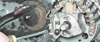
Generator URAL 4320 connection diagram
The URAL 4320 generator connection diagram with a voltage regulator is a generator set that is part of the electrical equipment system of the URAL 4320 vehicle. Generator 1702.3771 allows you to operate in any operating mode of the URAL 4320 so that the battery charge does not drop. The non-contact type voltage regulator is used to maintain constant voltage in the electrical connection circuit of the URAL 4320 vehicle.
Generator URAL 4320 – 1 – generator; 2, 7 – bolts; 3, 8 – nuts; 4 – generator mounting bracket; 5 – washer; 6 – finger; 8 – spring washer
The installed generator 1702.3771 or G 288E of the URAL 4320 car is a synchronous electric machine with a built-in rectifier unit, with forced ventilation.
Connection diagram for generator URAL 4320
1 – generator URAL 4320; 2 – voltage regulator; 3 – capacitor filter; 4 – voltage regulator disconnect relay; 5 – red wire from the “+” terminal of the generator to the “+” terminal of the current indicator; 6 – red wire from the electric torch device (EFD) button; 7 – red wire to an additional resistor with an electrothermal relay; 8 – blue wire from the “VK” terminal of the starter switch and instruments; 9 – black wire from the generator phase output “W” to the starter interlock relay and tachometer
Electrical diagram
The electrical circuit in the Urals, unlike the BMW, is built on a single-wire version. The disadvantage is the metal frame; the voltage is 12 volts. The main advantage of the Ural motorcycle is its simplicity and ease of repair. You can even repair your motorcycle on the road. The ability to independently adjust the electrical system according to the wiring diagram makes it simply irreplaceable.
Each model can literally be remade to suit you, configure and clean the power system, adjust the wiring and, in case of breakdown, replace the damaged parts yourself with new ones.
The electrical circuit diagram of the Ural motorcycle includes:
- Side light lamp;
- Spark plug;
- Rotor;
- Brake signal;
- Relay regulator;
- Rotor breaker;
- Capacitors;
- Ignition distributors;
- The ignition switch itself and the key to it;
- Primary and secondary windings in a coil;
- The ignition coil itself;
- Accumulator battery;
- Fuse box;
- Generator;
These are the main points of the electrical equipment diagram, changing and adding new points depending on the configuration of the model. Newer models have many upgraded parts that are significantly different from older versions. However, single-pole terminals are used throughout, reducing power consumption and requiring less wiring. Unipolar terminals are a point due to which the motorcycle breaks down much less.
Variety of schemes
Wiring often deteriorates when exposed to the external environment and you have to buy a new one. How to connect new wiring and understand it? The main connection problem in the Urals is the display of side lights, high and low beams, turn signals, and other light bulbs on the dashboard. It’s easy to get confused in a large number of wires and terminals, so you need to call them one by one.
Approximately, the procedure for connecting is as follows:
- Find the wiring diagram for your motorcycle model.
- Looking at the diagram, select the first terminal.
- It is recommended to start with the central “W” on the relay.
- Using the diagram, look at the direction of the wire and where exactly it should be connected.
- Solder the end of the wire to the desired terminal.
When connecting dimensions, it is necessary to include a fuse in the circuit. And the high and low beams are in any case soldered to the switch on the central contact (combination). When connecting turn signals, one wire goes from the center contact with the switches to the relay to receive power.
You need to avoid getting confused which wire goes to the right and which to the left; try marking them for yourself.
For ease of working with electronics and settings, there is a car strobe light. It was created for cars, but is also well suited for motorcycles; if you know someone who has such a unit, borrow it and make your life much easier. There are many circuits for wiring a motorcycle, each with its own characteristics. It is necessary to initially decide on a scheme, and then simply act step by step.
Electrical diagram
The wiring diagram for the Urals includes:
- Spark plug;
- Ignition distributor (rotor);
- Distributor breaker;
- Secondary winding in the ignition coil;
- Primary winding in the ignition coil;
- Actuator mechanism (hammer) of the breaker;
- Actuating cams for breaking the camshaft contact;
- Breaker Anvil;
- Ignition system capacitor;
- Distributor;
- Rechargeable 6V battery;
- Headlight;
- Ignition switch with key;
- Ignition switch contact group;
- Ignition coil.
Note! The proposed instructions described in detail not only the adjustment points, but also the repair methods in the event of an accident or failure of the electrical components of the Ural motorcycle.
However, the wiring of the Ural motorcycle was modified every time the domestic industry introduced new quality standards.
In addition, the appearance of additional equipment on models:
- Side lights;
- More capacious battery;
- Automatic ignition timing regulator;
made some adjustments. In particular, the new electrical wiring for the Ural motorcycle was a more complex system (pictured below).
Color scheme of M-72 motorcycles
Further operation showed that the six-volt wiring diagram for the Ural motorcycle is futile. And it was, as expected, replaced by more modern equipment designed for 12V.
This was greatly facilitated by the introduction of GOST 3940-71 for automotive and tractor electrical equipment, which occurred in 1975. In particular, the wiring to the Ural M-67 and Dnepr MT10, produced by IMZ and KMZ, met the requirements of a 12-volt electrical system.
Excursion into history
It is generally accepted that the prototype of the Urals was the German motorcycle BMW R-71, the drawings of which were officially purchased in the fortieth year of the last century.
After studying and developing the technical documentation, the domestic M-72 motorcycle was born, which had some differences from the prototype:
- The model was equipped with a double-disc clutch (in German, a single-disc clutch was used);
- The final drive ratios were increased, which increased its cross-country ability in off-road conditions;
- The wiring diagram of the Ural motorcycle was chosen to be single-wire (on the German prototype it was two-wire);
- The entire electrical circuit was built on a voltage of 6V (later switched to 12 volts);
- The ignition timing for different engine operating modes was given manually.
A feature of domestic motorcycles was the ease of do-it-yourself maintenance - any breakdown or malfunction could be solved in the field.
Over the course of several years, no more than 7,000 copies were produced at all enterprises that mastered the production of motorcycles:
- Moscow Motorcycle Plant (MMZ had the most massive production of the M-72);
- Gorky Motorcycle Plant (GMZ);
- (Leningrad);
- Kiev Motorcycle Plant (KMZ);
The main production of Ural heavy motorcycles was launched at the Irbit motorcycle plant, located in the Sverdlovsk region, where MMZ production equipment was evacuated at the beginning of the war.
For reference: The Irbit motorcycle plant, formed on the territory of the brewery in November 1941, is considered to be the ancestor of the M-72 motorcycle, called “Ural-1”. Throughout the years of its activity, its only specialization was the production of heavy motorcycles. And all the military videos featured exclusively his products.
Period 1941-1954
Having appreciated all the advantages of the motorcycle in the conditions of hostilities, it was decided to increase their production several times. In 1942 alone, the Irbit Motorcycle Plant produced almost 10,000 Ural-1 motorcycles. In the post-war years, the annual target was 20,000 motorcycles.
The main customers were:
- RKKA (Workers' and Peasants' Red Army, later renamed the Soviet Army);
- Law enforcement service (police);
- Consumer cooperation (in the post-war period);
- Population (did not go on sale until the mid-50s).
For reference: Over the two decades since its release, the motorcycle has proven its worth as a mobile vehicle, most suitable for use in off-road and urban environments.
Period 1955-1964
The wiring of the Ural motorcycle also performed well - if at first the designers had concerns about loss of contact due to possible corrosion of the metal frame, then operation showed the reliability of the single-wire electrical circuit.
However, with the release of the transitional model IMZ M-61 and, on its basis, the new Ural model M-62 (in 1961), the following were modernized:
- Transmission,
- steering;
- ignition system.
In particular, automatic ignition timing was introduced, since the motorcycle received a new power unit, and the old manual control of the timing advance did not meet the technical requirements.
The new electrical wiring for the Ural motorcycle connected into a single system:
- Battery model 3MT-12 with a voltage of 6V;
- Relay-voltage regulator model PP-31;
- Generator brand G-414;
- Distributor chopper with ignition advance system PM05;
- Ignition coil model B201.
In just a couple of years, Ural modifications appeared in the production program of the Irbit Motorcycle Plant:
- IMZ M-61 (transitional model for testing a new overhead valve engine);
- M-63 “Ural 2” (the frame was modernized and a new exhaust system was introduced, which made it possible to increase ground clearance);
- M-66 “Ural 3” (the wiring diagram for the Ural motorcycle was replenished with direction indicators and new side lights);
For reference: a large number of models under the Ural brand and alphanumeric indices often create confusion. For example, the wiring diagram of the Ural 4320 implies the electrical system of an off-road truck, and the wiring diagram of the Ural 5557 implies its modifications, and not one of the varieties of a heavy motorcycle.
Historical reference
Pre-war period
From archival documents it follows that a group of engineers appointed by the Soviet leadership considered it expedient to use the BMW R-71 product as the basis for the future motorcycle..
German BMW R-71 model 1940
For reference: The group studied all commercially produced motorcycles available in those years. And based on a number of characteristics, she determined the most promising configuration, which was exactly what the BMW brand corresponded to. However, according to Soviet engineers, some of the components and assemblies, as well as the central wiring, needed modification to suit domestic operating conditions.
The project was approved by the Soviet leadership and already in 1940 pre-production samples were ready for testing, which had:
- The wiring diagram of the Ural motorcycle was based on a single-wire version (the metal frame acted as a “minus”), while BMW used a two-wire one;
- 6V voltage was chosen (in the post-war years, 12-volt equipment was considered promising);
- For stable operation on a lean fuel mixture, a manual ignition timing regulator was installed;
- To improve motorcycle performance in off-road conditions:
- a double-disc clutch was installed (the BMW R-71 was equipped with a single-disc clutch);
- In the gearbox, the final drive ratios have been increased.
The main feature of the first heavy domestic motorcycle was its simplicity:
- you could fix any breakdown along the way with your own hands;
- adjust the electrical system (the electrical wiring of the Ural motorcycle allowed this);
- clean and adjust the power system;
For reference: In pre-war times, more than 7,000 motorcycles entered service. Their production was carried out by the Moscow Motorcycle Plant (MMZ), the Gorky Motorcycle Plant (GMZ), the Leningrad and Kiev Motorcycle Plants (KMZ).
War time
With the outbreak of war, motorcycle production was urgently evacuated to Sverdlovsk and quickly launched at the Irbit motorcycle plant. The donor of the new production was all the equipment removed from the Moscow Motorcycle Plant. And the finished products went straight from the assembly line (pictured below) to the customer.
Directly from the factory, the militia went to the front on M-72 Ural motorcycles
The military appreciated the high quality and ease of maintenance of the motorcycle. Their defense order has increased several times. The team of the Irbit Motor Plant managed to increase the volume to 10,000 Ural-1 in 1942 alone, and subsequently exceeded the mark of 20 thousand units.
Emblem of the Irbit Motor Plant
Note! The original name “Ural” exists not only in the designation of heavy motorcycles, but also trucks, which contributes to a little confusion. In particular, the Ural 4320 wiring diagram is related not to a motorcycle, but to a car. The wiring diagram of the Ural 5557 is deciphered in a similar way - this is a modification of a truck.
Post-war time
The accumulated operating experience in the most severe conditions has proven the promise of the chassis and the design as a whole (this is clearly shown in the video presented at the end of the article), which allowed the factory designers to focus on improving the functionality of the motorcycle.
For reference: Although the 6V wiring diagram for the Ural motorcycle was considered obsolete, it was nevertheless retained due to the amazing stress resistance of the design.
Along with the main customer (the army), the IMZ production program also included:
- law enforcement agencies (police);
- security organizations such as fisheries inspection;
- fire services;
- medical services, etc.
The production of fire-fighting versions was mastered by a plant in Dnepropetrovsk in the 80s.
For reference: The wiring diagram for a Ural motorcycle with a fire pump provided for reliable starting in any conditions.
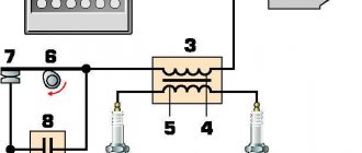
Electrical equipment of the motorcycle Ural M 72
The electrical equipment of the Ural M 72 motorcycle consists of the following devices and units: a G-11A generator; battery Z-MT-7 or Z-MT-14; relay-regulator RR-31; ignition coils IG-4085-B; breaker-distributor PM-05; spark plugs NA11/11AU; FG-6 headlights, lighting lamps, signal, switches and warning lamp.
The spark plug NA11/11AU is a collapsible type, consisting of: uralite insulator 1; central electrode 4; steel body 2; side electrode 5; insulator nuts 3; two copper gaskets 6; one copper-asbestos gasket 7. The central electrode is covered on top with a carbolite tip 5. The spark gap between the central and side electrodes should be 0.7 mm.
The FG-6 headlight consists of a housing 1, a rim 2 with a lens, a reflector 3 with a double-filament lamp 4 and a parking light lamp 5. The headlight housing contains a central switch 6, a high and low beam switch 7, a speedometer 8, a warning lamp 9 and a fuse 10 The various positions of the central switch are switched on using key 11. There are wire holders on the sides of the headlight housing.
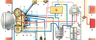
Electrical diagram of the M 72 motorcycle.
The required driving tool is shown below.
How to install lights on a Ural motorcycle
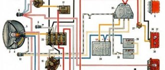
Electrical circuit diagram for Ural motorcycles
Electrical diagram of motorcycles "Ural" M62, M63, M66:
1 — direction indicator switch P-201; 2 - right direction indicators with A6-15 lamps on a single motorcycle; 3 — connecting block; 4 — headlight lamp A6-32+32; 5 — parking light lamp for headlight A6-2; 6 — relay-interrupter of direction indicators; 7 — left direction indicators with lamps from A6-15; 8 — sound signal S-37A; 9 — light switch with sound signal button P-200; 10 — speedometer scale illumination lamp A6-2; 11 - 15A fuses; 12-centre switch; 13 — generator G-414; 14 — control lamp for generator operation A6-0.25; 15 — relay-regulator PP-302A; 16 — ignition coil B201; 17 — breaker ROM1302; 18 — right direction indicators with lamps A 6 -15 (on a stroller); 19 — front parking light on a sidecar with lamp A6-2; 20 — brake light lamps A6-15; 21 — rear marker lamps A6-22; 22 — battery ZMT-6; 23 — brake light switch; 24 — warning lamp for emergency oil pressure A6-2; 25 - oil pressure sensor (only Ural M66 are equipped with direction indicators)
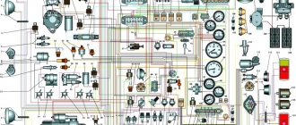
Electrical diagram of motorcycles “Ural” M67 and M67-36:
1 — right direction indicators on a single motorcycle with A12-21-3 lamps; 2 — headlight lamp A12-45+40; 3 front parking light lamp A12-4; 4 — left direction indicators with lamps A12-21-3; 5 — direction indicator switch P201; 6 — relay-interrupter of direction indicators; 7 — indicator lamp A12-1; 8 — speedometer scale illumination lamp A12-1; 9 — fuse block; 10 — control lamp for generator operation A12-1; 11 — ignition switch VK857; 12 — light switch with sound signal button P200; 13 — sound signal S205B; 14 — right direction indicators with lamps A12-21-3; 15 — front side light with lamp A12-5; 16 — relay-regulator PP-330; 17 — generator G-424; 18 — ignition coil B204; 19 — spark plugs A14B; 20 — breaker PM302A; 21 — tail light and brake light lamp A12-21+5; 22 — brake light lamp A12-21-3; 23 — brake light switch; 24 - 6MTS-9 or two ZMT-6 batteries; 26 - ground switch
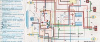
Electrical circuit diagram for Ural motorcycles IMZ-3.103-10; IMZ-8.103-30; IMZ-8.103-40 and IMZ-8.123:
1 - emergency ignition switch; 2 — day-night switch; 3 — plug connector blocks; 4 — handbrake brake light switch; 5 — relay-interrupter of direction indicators; 6 — fuse block; 7 — neutral control lamp in the A-12-1 gearbox (green); 8 — indicator lamp A12-1 (orange); 9 — lamps A12-1 for illuminating the speedometer scale; 10 — headlight lamp A12-45+40; 11 — side (parking) light lamp in headlight A12-4; 12 — left direction indicators with lamps A12-21; 13 — high beam indicator lamp A12-1 (blue); 14 — control lamp for generator operation A12-1 (red); 15 - ignition switch; 16 — direction indicator switch; 17 — light switch; 18 — right direction indicators (on a wheelchair) with lamps A12-21; 19 — side (parking) light lamp on the front sidecar A12-5; 20 — two-filament lamp for rear parking light and brake light A12-21+5; 21 — relay-regulator PP-330; 22 — foot brake brake light switch; 23 — ground switch; 24 — neutral control lamp switch; 25 — sound signal S-304; 26 — ignition coil B204; 27 — generator G-424 with rectifier; 28 — breaker PM302A; 29 — sound signal button; 30 — lamp AI2-21 brake light; 31 — lamp A12-5 rear marker (parking) light; 32 — 6MTS-9 battery (or two ZMT-b batteries); 33 — switch of the contactless electronic ignition system (BESZ); 34 — BESZ sensor; 35 - electronic voltage regulator 33 3702; 36 — right direction indicators on a single motorcycle with A12-21 lamps
Messages [21 to 40 of 54]
21↑ Reply from shaman507 04/15/2015 21:52:26
- shaman507
- Angry moderator
- Inactive
- Name: Evgeniy
- From: Tambov region
- Registered: 28-05-2013
- Messages: 4 350
- Reputation: 401
- Motorcycle: Dnepr MT 10-36, M-72, Ural IMZ-8.103-10, M-63, IZH-49, Militia Ural single, Minsk M-106
Re: wiring diagrams for motorcycles
Write the names of which contacts on your relay
22↑ Reply from kilerx37 04/15/2015 22:13:27
- kilerx37
- Newbie
- Inactive
- Name: Yuri
- From: Kokhma
- Registered: 22-06-2014
- Messages: 14
- Motorcycle: Ural
Re: wiring diagrams for motorcycles
My relay has (+ sh lk)
Added: 04/15/2015 22:13:27
Hello. Please tell me . I have a problem with the wiring on my Ural motorcycle. I can’t figure out where to put the end of the wire that goes according to the diagram to B3 on the relay. My relay does not have such a contact. (Pink wire) There is only + sh lx (electronic relay)
23↑ Reply from Luis 05/14/2015 10:35:00
- Louis
- Elder
- Inactive
- From: Sakhalin
- Registered: 07-04-2014
- Messages: 2 525
- Reputation: 160
- Motorcycle: Dnepr 11
Re: wiring diagrams for motorcycles
I came across it...maybe someone can help. everything seems to be correct. The drawings are not mine.
If something is wrong, correct it.
+6
24↑ Reply from pet.mikh.mikh 05/14/2015 16:18:50
- pet.mikh.mikh
- Elder
- Inactive
- Name: Mikhail
- From: Tyumen
- Registered: 20-05-2014
- Messages: 1 443
- Reputation: 81
- Motorcycle: Ural IMZ-8-103-10 1993
Re: wiring diagrams for motorcycles
Intelligible, catch +.
25↑ Reply from kilowatt3 05/14/2015 21:33:45
- kilowatt3
- Electrician
- Inactive
- Name: Alexander
- From: Belgorod region Alekseevka
- Registered: 24-03-2011
- Messages: 1 950
- Reputation: 197
- Motorcycle: Dnepr MT 11, but there were different ones and more than one!
Re: wiring diagrams for motorcycles
buddy, it’s correct and thorough, but people don’t like to search, you should probably create a separate thread marked important, and the name is a color guide for everyone.
26↑ Reply from Luis 05/15/2015 03:52:16
- Louis
- Elder
- Inactive
- From: Sakhalin
- Registered: 07-04-2014
- Messages: 2 525
- Reputation: 160
- Motorcycle: Dnepr 11
Re: wiring diagrams for motorcycles
The main thing is that everything is correct, you, as those who are knowledgeable in electrical engineering, have checked it, maybe in a separate topic..
27↑ Reply from Vadimka 01-10-2015 05:41:37
- Vadimka
- passerby
- Inactive
- Registered: 18-09-2015
- Messages: 3
Re: wiring diagrams for motorcycles
hi everyone. I have this problem: when turning left, the turns blink. When turning right, the headlight blinks. what should I do? Thank you
28↑ Reply from komandor 01-10-2015 19:32:58
- commander
- Seeker of new sensations
- Inactive
- Registered: 12-02-2015
- Messages: 753
- Reputation: 116
Re: wiring diagrams for motorcycles
hi everyone. I have this problem: when turning left, the turns blink. When turning right, the headlight blinks. what should I do? Thank you
What does "headlight flashing" mean? Is it on, but when you turn on the turns it starts to go out and then come on? If so, then somewhere in the “relay—>turn signal lamp” circuit there is a short circuit. And there is a voltage drop when the relay is activated.