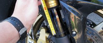
From time to time, questions arise with turn signal relays when LED lamps are installed in the turn signals on a motorcycle, and not only on motorcycles, but also on cars, or when the turn signals themselves are replaced entirely with LED ones. Standard relays, as a rule, refuse to work with such light bulbs because the load is too small. It (the relay) perceives the LED lamp as a broken wire and begins to switch faster than usual. Under normal conditions, this is convenient: the relay began to “click” faster than usual, which means that some light bulb has burned out. But for someone who has consciously replaced incandescent bulbs with LEDs, this is the beginning of a headache. Just a few years ago, electronic turn signal relays for LEDs cost about 500 rubles, which is not at all humane. Then I just needed a relay for the LEDs. After scouring the Internet, I found an article about converting a conventional automotive three-pin electronic turn signal relay into a relay for LEDs. I did everything as described, everything worked, I forgot. But lately, apparently, spring is taking its toll, and the question of relays for LEDs has often come up. Anyone interested, please see cat. Compared to what it was a few years ago. the situation seems to have improved. So, literally today, while corresponding here with one of the forum members, who ordered himself a special turn signal relay for LEDs, I found out that the prices for these relays have dropped. According to this forum member, he ordered himself a relay for 170 rubles. Today, I bought a regular car relay at a car store for the same 170 rubles. I suppose that I could find it cheaper, because... this store is far from the cheapest, but I live in a small town, there are few stores, I stopped by another store, they ran out of relays. And I don’t see the point in going somewhere else because of winning 10-20 rubles. So, let's move on to the remake. To understand what exactly and how we will remake, here is a relay diagram: The basis of the relay is a specialized integrated (on a microcircuit) pulse generator that controls the closing and opening of a small-sized relay. The microcircuit has a special pin that monitors the voltage drop across the shunt. This drop depends on the total resistance of the lamps connected (in parallel). If a lamp burns out, the resistance increases, the voltage drop across the shunt decreases, and the microcircuit begins to switch faster. If this pin of the microcircuit is turned off, it will give pulses at a constant frequency, regardless of the number and power of connected lamps, which is exactly what we need.
In the diagram, the pin that needs to be disconnected is crossed out.
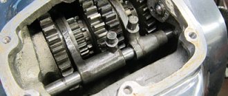
Now let's move on to practical implementation. I bought a relay like this: A wide strip of metal - it’s like the same shunt. View of the board with the microcircuit: We see the microcircuit. There is a dot on her body, it is always in the corner. This point calls the key. The key is always placed at the first pin of the microcircuit. The pins are numbered sequentially counterclockwise. If we return to the circuit, we need pin No. 7. I crossed out the conductor coming from him. This is the optimal place to cut the conductor. If someone buys another relay, more precisely, from a different manufacturer, the internals may differ in appearance. That's why I explain in such detail how to find the right conductor. I cut the track on the board with the tip of an ordinary knife, scratched it several times, saw that instead of the copper track the board was visible and that was enough. The current there is scanty, it won’t break through. The incision site is circled.
I would like to draw the attention of those who have a standard two-contact relay. This was exactly what happened on the old Yamaha R1-Z. Don't be scared! There is simply no mass wire there.
Relay connection. The relay has 3 outputs: 39 - ground, always connected. 49 - constant +, connects when the ignition is turned on 49a - signal, goes to the remote control, the turn switch and the emergency lights. To connect, you need to determine which wire is which in the standard wiring. If there is a diagram, good; if not, you need a test lamp. First, let's find the mass. One terminal of the test lamp is on the + battery, with the other we try the wires in the connector. The turn switch and hazard lights must be turned off. Where the lamp lights up, that is the mass output. We connect the wire of the probe lamp to any ground contact and try the wires in the connector, while not forgetting to turn on the ignition. But the lamp can light up in both wires (depending on the connection diagram of the control lamp in the device), so we turn on any turn signal or emergency lights. The wire where the probe lit up is the desired +. The remaining wire is the signal wire. You can check it by shorting the + and signal wires with the turn signals or emergency lights on. The turns should light up. If anyone is afraid, you can connect these 2 wires with a probe lamp, then the turn signals will light up, but dimly, and the probe is only slightly worse than when connected to the battery. And all because we turned on the turn signals in series with the probe.
Further, there are already possible options for who exactly will connect the relay to the standard connector. In such cases, I usually do not cut off the connector itself, but make an adapter from wires and terminals.
If anyone still doesn’t understand something, ask, I’ll try to answer. But I'll be away for the weekend, so there may be a delay in replies.
ps I made a video with the converted relay connected. If anyone is interested, please follow the link
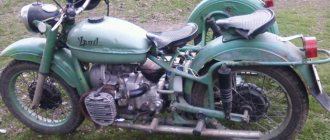
Features of the development of electrical equipment for Ural motorcycles
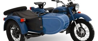
Over the years, the six-volt circuit ceased to meet technical regulations, and on subsequent models, manufacturers installed central wiring designed to operate 12V equipment:
- Rechargeable 12-volt battery;
- More powerful generator;
- Ignition coils;
- Headlights;
- Turning lamps and side lights;
- License plate lamps;
- Brake light lamp;
- Fuse box.
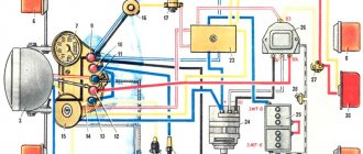
Modern wiring to the Urals M-67 according to GOST 3940-71
For reference: the introduction of GOST 3940-71 for automotive and tractor electrical equipment in 1975 forced the Irbit and Kiev motorcycle factories to upgrade the Ural M-67 and Dnepr MT10 motorcycles to a 12-volt electrical system.
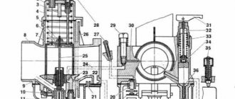
The 12-volt ignition system for Ural motorcycles consists of:
- power sources (battery and generator);
- ignition coils;
- low and high voltage wires;
- spark plugs;
- manual or automatic ignition timing regulator;
- central switch (ignition switch).
Messages [21 to 40 of 53]
21↑ Reply from shaman507 04/15/2015 21:52:26
- shaman507
- Angry moderator
- Inactive
- Name: Evgeniy
- From: Tambov region
- Registered: 28-05-2013
- Messages: 4 350
- Reputation: 402
- Motorcycle: Dnepr MT 10-36, M-72, Ural IMZ-8.103-10, M-63, IZH-49, Militia Ural single, Minsk M-106
Re: wiring diagrams for motorcycles
Write the names of which contacts on your relay
22↑ Reply from kilerx37 04/15/2015 22:13:27
- kilerx37
- Newbie
- Inactive
- Name: Yuri
- From: Kokhma
- Registered: 22-06-2014
- Messages: 14
- Motorcycle: Ural
Re: wiring diagrams for motorcycles
My relay has (+ sh lk)
Added: 04/15/2015 22:13:27
Hello. Please tell me . I have a problem with the wiring on my Ural motorcycle. I can’t figure out where to put the end of the wire that goes according to the diagram to B3 on the relay. My relay does not have such a contact. (Pink wire) There is only + sh lx (electronic relay)
23↑ Reply from Luis 05/14/2015 10:35:00
- Louis
- Elder
- Inactive
- From: Sakhalin
- Registered: 07-04-2014
- Messages: 2 525
- Reputation: 160
- Motorcycle: Dnepr 11
Re: wiring diagrams for motorcycles
I came across it...maybe someone can help. everything seems to be correct. The drawings are not mine.
If something is wrong, correct it.
+6
24↑ Reply from pet.mikh.mikh 05/14/2015 16:18:50
- pet.mikh.mikh
- Elder
- Inactive
- Name: Mikhail
- From: Tyumen
- Registered: 20-05-2014
- Messages: 1 443
- Reputation: 81
- Motorcycle: Ural IMZ-8-103-10 1993
Re: wiring diagrams for motorcycles
Intelligible, catch +.
25↑ Reply from kilowatt3 05/14/2015 21:33:45
- kilowatt3
- Electrician
- Inactive
- Name: Alexander
- From: Belgorod region Alekseevka
- Registered: 24-03-2011
- Messages: 1 950
- Reputation: 197
- Motorcycle: Dnepr MT 11, but there were different ones and more than one!
Re: wiring diagrams for motorcycles
buddy, it’s correct and thorough, but people don’t like to search, you should probably create a separate thread marked important, and the name is a color guide for everyone.
Electrical diagram
The wiring diagram for the Urals includes:
- Spark plug;
- Ignition distributor (rotor);
- Distributor breaker;
- Secondary winding in the ignition coil;
- Primary winding in the ignition coil;
- Actuator mechanism (hammer) of the breaker;
- Actuating cams for breaking the camshaft contact;
- Breaker Anvil;
- Ignition system capacitor;
- Distributor;
- Rechargeable 6V battery;
- Headlight;
- Ignition switch with key;
- Ignition switch contact group;
- Ignition coil.
Note! The proposed instructions described in detail not only the adjustment points, but also the repair methods in the event of an accident or failure of the electrical components of the Ural motorcycle.
However, the wiring of the Ural motorcycle was modified every time the domestic industry introduced new quality standards.
In addition, the appearance of additional equipment on models:
- Side lights;
- More capacious battery;
- Automatic ignition timing regulator;
made some adjustments. In particular, the new electrical wiring for the Ural motorcycle was a more complex system (pictured below).
Color scheme of M-72 motorcycles
Further operation showed that the six-volt wiring diagram for the Ural motorcycle is futile. And it was, as expected, replaced by more modern equipment designed for 12V.
This was greatly facilitated by the introduction of GOST 3940-71 for automotive and tractor electrical equipment, which occurred in 1975. In particular, the wiring to the Ural M-67 and Dnepr MT10, produced by IMZ and KMZ, met the requirements of a 12-volt electrical system.
Excursion into history
It is generally accepted that the prototype of the Urals was the German motorcycle BMW R-71, the drawings of which were officially purchased in the fortieth year of the last century.
After studying and developing the technical documentation, the domestic M-72 motorcycle was born, which had some differences from the prototype:
- The model was equipped with a double-disc clutch (in German, a single-disc clutch was used);
- The final drive ratios were increased, which increased its cross-country ability in off-road conditions;
- The wiring diagram of the Ural motorcycle was chosen to be single-wire (on the German prototype it was two-wire);
- The entire electrical circuit was built on a voltage of 6V (later switched to 12 volts);
- The ignition timing for different engine operating modes was given manually.
A feature of domestic motorcycles was the ease of do-it-yourself maintenance - any breakdown or malfunction could be solved in the field.
Over the course of several years, no more than 7,000 copies were produced at all enterprises that mastered the production of motorcycles:
- Moscow Motorcycle Plant (MMZ had the most massive production of the M-72);
- Gorky Motorcycle Plant (GMZ);
- (Leningrad);
- Kiev Motorcycle Plant (KMZ);
The main production of Ural heavy motorcycles was launched at the Irbit motorcycle plant, located in the Sverdlovsk region, where MMZ production equipment was evacuated at the beginning of the war.
For reference: The Irbit motorcycle plant, formed on the territory of the brewery in November 1941, is considered to be the ancestor of the M-72 motorcycle, called “Ural-1”. Throughout the years of its activity, its only specialization was the production of heavy motorcycles. And all the military videos featured exclusively his products.
Period 1941-1954
Having appreciated all the advantages of the motorcycle in the conditions of hostilities, it was decided to increase their production several times. In 1942 alone, the Irbit Motorcycle Plant produced almost 10,000 Ural-1 motorcycles. In the post-war years, the annual target was 20,000 motorcycles.