Unlike similar Soviet-era motorcycle models, the electrical wiring diagram of the IZH Jupiter 5 motorcycle provides for operation from a battery with air-cooled equipment. This causes many problems for owners. The article provides recommendations for modernization that solves problems with sparking.
Features of electrical equipment
Models of IZH motorcycles are as unified as possible. The wiring diagram for IZ Jupiter 2 is not much different from later versions of the IZ motorcycle. There are external differences. For example, the Planet 5 bike has one cylinder, and the Jupiter 5 has two.
The first 12-volt motorcycle was the IZH Jupiter 4. The wiring diagram for the IZH Jupiter 5 and the wiring diagram for the IZH Jupiter 3 differ in components.
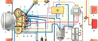
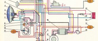
Wiring diagram IZ Jupiter 5
The bike of the fifth Jupiter has a contact SZ, which is powered by a battery, so the operation of the vehicle is highly dependent on the state of charge of the battery.
If charging is insufficient, the following problems occur:
- the motor runs intermittently;
- the engine starts with difficulty;
- At low speed the battery is discharged.
These problems can be eliminated by switching to BSZ. Any electrician can handle this task (the author of the video is Viter Electronic).
How to make the transition to contactless SZ?
To switch to contactless SZ, motorcyclists use parts from other motorcycle models. When upgrading the generator set, the wiring of the IZH Jupiter 5 remains unchanged. Minor alterations concern the electrical circuit of the IZH. After changes, the battery is used to service auxiliary equipment. To switch to BSZ, parts are taken from Planet 5 and the VAZ 2108 car.
The following changes are being made to the electrical circuit of IZH:
- install 2 Hall sensors from the eighth VAZ model;
- 2 VAZ electronic switches must be connected to the sensors;
- each of the cylinders serves a commutator-sensor pair;
- You need to add two more ignition coils to the circuit.
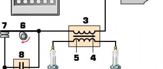
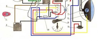
SZ after modernization
On the electrical circuit of the IZH motorcycle, the components are marked with numbers:
- Spark plug.
- Ignition coils from Planet 5.
- Switches.
- Hall sensors.
- Egnition lock.
- Battery.
For the created ignition system, it is necessary to modify the IZ Jupiter 5 generator, the circuit of which will not require major changes.
How can I modify the generator?
The presented modernization option is advantageous in that it does not require the purchase of a new generator that will service the new ignition system.
Recycled generator design
All you need to do is follow these steps:
- make a modulator-breaker of an electrical circuit;
- install a breaker on the rotor shaft or generator.
You can create a modulator with your own hands. To do this, you need to take a metal plate and drill a hole in it for the fastening bolt. The manufactured part will serve as a modulator-chopper.
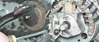
Homemade modulator for interruption
The modulator is connected as follows:
- install the modulator plate (2) and tighten it with the bolt (3), but not all the way;
- by rotating the crankshaft, you need to ensure that the piston is at top dead center;
- Next you need to set the ignition timing;
- Now you can tighten the mounting bolt on the plate.
Hall sensors (1) are installed together with the modulator.
If something is wrong.
- Disconnect the relay regulator (remove the connector). Let's take a tester.
- We set the tester to measure resistance. We check the resistance between ground (engine) and the generator wires (three wires, usually yellow). It shouldn't exist. If at least one has it, your motorcycle's alternator has burned out.
- We check the resistance between the generator wires, the resistance should be the same, about 1 - 3 ohms. If it is more or not the same, your motorcycle's alternator has burned out.
- We set the tester to measure alternating voltage. We start the motorcycle, measure the voltage between the generator wires, it should be more than 18 volts at idle, and more than 40 volts at 3000 - 4000 rpm. If there is no or different voltage, your motorcycle's alternator has burned out.
- If the check in points 2, 3 and 4 went well, most likely your motorcycle has a faulty Relay - Regulator or, which also happens, a wiring fault (clean all terminals, check the integrity of the wires, connections to ground). If your motorcycle's generator burns out, this is the place for you: Rewinding the generator with your own hands.
Improving the standard system
The ignition system can be improved in other ways. To do this, you need to identify what problems there are with the wiring. They can occur in the primary circuit between the coil and the 12V battery or due to operating conditions. A visual inspection of the primary circuit can reveal problems with connections, contacts and the ignition switch.
If operating conditions are ideal, the primary circuit will operate with a 12V battery without failure.
But when dirt and dust get into the circuit, the resistance at the contact points increases, which entails a decrease in voltage from 12 Volts to 7-8 Volts. This voltage is not enough for a powerful discharge to appear in the secondary winding of the coil. As a result, a charge of less than 12 V appears on the spark plug, which poorly ignites the combustible mixture in the cylinders. Burnt contacts, oily spark plugs and batteries with a charge of less than 12 V further worsen sparking.
Generator care
Comes down to visual inspection and cleaning.
First of all, you need to pay attention to parts subject to wear. The carbon brushes of the current collector wear out faster than other parts. They require regular inspection and are replaced if worn. The slip rings of the slip ring must be kept clean. You cannot clean it with sandpaper or needle files. You can use the finest glass sandpaper.
The breaker contacts are periodically checked for the gap value specified in the instructions. For Planet 4 the gap is 0.4 - 0.6 mm. In case of burning, the contacts are leveled and then polished to a mirror finish.
Video “Installing BSZ on IZ Jupiter 5”
This video talks about installing a contactless ignition system on a Jupiter 5 motorcycle (the author of the video is Andrey).
I have in my garage my “Old Friend” IZH Yu-5, which was given to me when I graduated from school! The only owner of which is only me. I haven’t driven it for a long time, more than 10 years, and it wouldn’t start, there was no charging, constant problems with the cams and dead ignition coils, and of course the right pot! It's time to revive your comrade! It was decided to install the BSZ, do normal charging with car elements and replace the wiring! I go to the store and buy parts:
1. Relay - regulator 2101, 2106. 2. Generator diode bridge (suitable for VAZ and GAZ generators. 3. Capacitor for diode bridges (in my opinion, they are all the same for VAZ and GAZ) 4. 2 spark plugs from GAZ with an electronic ignition system. 5 . 2 short high-voltage silicone wires (I bought it for fifty dollars in some garage cop) 6. Ignition coil (VAZ 1111, GAZ with engine 406) two-terminal, dry 7. Switch (VAZ 2108) 8. Hall sensor (VAZ 2108) 9. Connecting blocks for the switch and the Hall sensor 10. Emergency ignition (just in case) 11. Terminals, wires, electrical tape and nut - I think everyone has them in the garage 12. I ordered a modulator plate and a hall sensor mounting plate on the Internet to sharpen myself it was a mess))
Installing the BSZ 1. Remove the breaker contacts, coil, capacitor and all other crap from the contact ignition. 2. We put the switch in the right glove compartment, the coil under the tank. 3. Unscrew the generator bolt. 4. Install the modulator. 5.Attach the Hall sensor. 5.1. We fasten the modulator, but do not tighten it! 6.We connect everything according to the following scheme. Save to Album Diagram 1 Diagram 1
7. We put the armor wire on the spark plug and connect it to the coil. Everything is done according to the first scheme, everything is done in an elementary way and in terms of time you can do it in an hour with smoke breaks. 8. Connect the ignition coil. Save to Album 2 color scheme 2 color scheme
The ignition is set simply: the piston is at TDC further 3.5 mm back and for the convenience of finding the moment of the spark, an instant diagnostic unit “MD-1” was purchased
Next, we are engaged in charging 1. We throw out all the elements of the old charging system 2. Brushes. Since the relay-regulator used controls the current on the rotor through (+), you need to do the following. Plastic blocks are installed on the generator housing, which allow you to isolate the wire connections from the housing. We find the connection between the white brush wire and the short wire with the black wire and release the brush wire (unscrew the nut on M3). There is a 3mm terminal mounted on it, we drill it out to 4mm. And now we put this terminal on the mounting screws of the block itself and tighten it, thereby applying it to the brush (-). 3. Diode bridge. On the BPV, black wires (-) go to the lower left part of the BPV and red wires (+) to the middle lower part of the BPV. And three pink ones on the right side of the GSV. We release the black ones and twist them, and we do the same with the red ones. And we remove the pink ones (they come from the generator from each phase and supply alternating current from each phase, of which there are only three) and leave them as is. The diode bridge consists of two plates, one of them is (+), the other (-) and they are insulated from each other, the plate that has insulation on the mounting hole (at the end) is (+). We connect the red wires (+) to plate. And we connect the black and brown ones to ground (-). The diode bridge is connected. 4. Relay regulator. Take (+) anywhere after the ignition key. This terminal will go to the groove size No. 15. We take the wire (+) of the brush, it was removed from the lower right part of the BPV, this is the wire for terminal size No. 67. We take the solution and connect it. Next, we screw the solution to ground; you can’t start it without this, otherwise it will burn out! 5. To make sure the charging light on the dashboard goes out, run it through the relay.
Checking the motorcycle's charging.
- We take a tester and set it to measure constant voltage (if there is a gradation of measurements, set it to 20 V). We measure the battery with the motorcycle not running. A fully charged battery is 12.8 - 12.9 volts (if less, it is advisable to charge the battery so that further measurements are correct, and also check the battery - you can read how to do this in the article: How to check the battery .)
- If the battery is serviceable and infected, we proceed to check the charging of the motorcycle. We measure the voltage on the battery with a tester, with the motorcycle running (idling, without consumers turned on: lights, heated handles, etc.), the voltage should be 13-15 volts. If the motorcycle charging test does not meet the criteria, move on.
- We turn on only “natural consumers” (lights), the voltage should be at least 12.8 volts (ideally, about 13.5 volts). If less, something is wrong.
- We turn on all consumers (additional equipment), if the voltage drops below 12.8 volts, try raising the idle speed to 1000 - 1100, the voltage should be at least 12.8 volts. If it is smaller, the generator does not pull all consumers (additional equipment) and may burn out.
- We give the gas 3000 - 4000 revolutions, the voltage should rise to 13 - 15 volts with all consumers turned on. On some motorcycles, the voltage rises to a maximum at 3500 -4000 rpm, and at higher rpm it drops, but not more than 13 volts (this is due to increased load at high rpm: the injectors begin to consume more power (they are open almost all the time), this is normal ). If less, something is wrong.
Features of electrical equipment
Despite the unification of parts with other models, the IZH Yu5 wiring diagram was chosen for battery use.
We are talking about a contact ignition system, which, if the battery is dead, immediately creates problems for the owner:
- Starting the engine is difficult;
- The engine runs intermittently;
- Driving at low speeds further drains the battery.
Therefore, many owners prefer to upgrade their ignition system with their own hands to a more progressive one - a contactless electronic type. It should also be noted that repairing the wiring of IZ Jupiter 5 should there be a desire for such an upgrade (see also the article about the wiring diagram of IZ Planet 5).
For reference: unlike the Jupiter model, new wiring and an electronic ignition system were installed on the modified IZ Planet 5. The methods proposed below are designed for simplified work - not requiring major replacement of components.
Transition to a contactless ignition system
Over the years of operation, the owners of IZH Jupiter 5 have developed more than one instruction for altering the electrical network. And almost all of them are based on elements from other domestic motorcycles (see also the features of the Ural motorcycle wiring diagram).
But there is a more progressive way in which:
- The generator and wiring remain on IZ Jupiter 5;
- Minor modifications are made to the electrical circuit;
- The battery remains for servicing auxiliary systems.
Content:
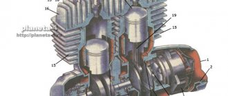
The fifth Jupiter model belongs to the middle class of road motorcycles, can travel on roads with different surfaces and, what is very important, is equipped with a cargo or passenger trailer with a carrying capacity of up to 100 kg, slightly inferior in loading to the Ural motorcycle with a sidecar. Other positive properties of IZ Jupiter 5 include:
- Powerful engine.
- Maintainability (do-it-yourself repairs are possible even in rural conditions).
- Economical to operate.
- Affordable price.
- High-quality electrical circuit with a powerful generator.
Among the technical parameters of the motorcycle, the main ones should be highlighted:
- power – 25.0 l. With.;
- engine volume – 348 cubic meters. cm;
- type of lubrication – joint;
- highest speed – 125 (95 with trailer) km/h;
- fuel – gasoline A76;
- cooling – air;
- frame design – welded tubular;
- electrical equipment voltage – 12 volts (battery sources, generator).