Engine smokes
IZH Jupiter 5 electrical diagram, IZH Jupiter 5 electrical diagram with symbols, IZH Planet 5 electrical diagram, IZH Planet 5 motorcycle electrical diagram, Electric Planet 5-01
The latest models of motorcycles Planet 5-01, Planet 6 use a 12-volt electrical system with a permanent magnet generator and an ignition system independent of the presence of a battery (Fig. 5.2). The new ignition system also provides automatic control of the engine ignition timing depending on the crankshaft speed.
Over the 50 years of production of IZH motorcycles, the electrical equipment system has fundamentally changed three times.
A 6 V electrical system with a 45 W DC generator was used on motorcycles from IZH350 to IZHPZ, IZHYUZ inclusive.
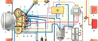
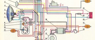
The increased intensity of traffic flow and the emergence of special requirements for motorcycle lighting devices required the transition to a 12 V electrical system with an alternating current generator with a power of 100-140 W. The disadvantage of this system in comparison with the previous one is a significant complication both in the number of devices and in switching. In addition, it requires a charged battery to start the engine, which is both a technical and economic disadvantage for motorcycle consumers. This system is used on models IZhYu4, IZhP4, IZhYu5, IZhP5 (Fig. 5.1).
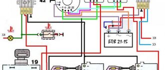
Rice. 5.1. Electrical diagram of motorcycles Planet 5, Jupiter 5:
1- parking light lamp A12-4; 2- high-low beam lamp A12-45-40; 3- control lamp for generator operation A12-1; 4- oil pressure warning lamp A12-1; 5.6- speedometer scale illumination lamps AMN 12-3; 7, 15, 16, 19, 22, 32 - direction indicator lamps for motorcycle and side trailer A12-21-3; 8- right switch; 9- handbrake brake light switch; 10- breaker; II- breaker; 12- block rectifier-voltage regulator BPV 14-10; 13- foot brake brake light switch; 14 and 18 - side trailer size lamps A12-5; 17- brake light lamp for side trailer A12-21-3; 20- brake light lamp A12-21-3; 21- motorcycle rear marker lamp A12-5; 23 - rechargeable battery; 24 - fuse; 25 - oil pressure sensor; 26-neutral lamp switch; 27- ignition coil; 28 - spark plug; 29-ignition switch; 30 - sound signal; 31- left switch; 33- turn signal switch; 34 - high beam indicator lamp A12-1; 35 - neutral control lamp A12-1; 36 - indicator lamp AMN 12-3.
: O - orange, G - blue, F - yellow, Kch - brown, P - pink, S - gray, K - red, F - purple, Ch - black, 3 - green.
Symbols on the BPV 14-0 block (item 12)
: — XI — “minus” of the excitation winding; — X2 — “minus” of the battery (weight); ХЗ - “positive” output to the control lamp; X4, X5, X7 - phases of the stator winding of the generator; X8 is the “plus” of the battery.
Note.
On a motorcycle with a side-trailer, the side-trailer tail light is connected to the green and red wire connectors going to the motorcycle's rear light (shown with a dotted line in the diagram). The wire from the side trailer turn signals is connected instead of the right rear motorcycle turn signal. The turn signal lights on the right side of the motorcycle are moved to the side trailer. On motorcycles with joint lubrication pos. 4, 25 are not installed.
Depending on the functional connections of individual devices and their intended purpose, the electrical equipment of motorcycles can be divided into the following main systems:
1. Power supply system (battery, generator, rectifier-regulator unit).
2. Ignition system (ignition coils, spark plugs, spark plug tips, breakers).
3. Lighting system, light and sound alarm (headlight, side lights, brake lights, turn signals, turn signal switch, retroreflectors, sound signal).
4. Instrumentation (speedometer, optical signaling devices).
5. Switching and protective equipment (switches, breakers, fuses).
6. Installation electrical products (tips, electrical wire connectors, electrical wires).
On IZH-Planet and IZH-Jupiter motorcycles, a single-wire electrical circuit is used, that is, the second wire connecting consumers to power sources is the mass of the motorcycle. The negative terminals of power supplies and consumers are connected to ground. The interconnection of all instruments and electrical components of the motorcycle is carried out according to the installation diagram (Fig. 5.1).
On motorcycles Planet 5, Jupiter 5, the ignition switch (lock) ensures that electrical equipment is switched on in accordance with Table. 5.1.
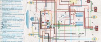
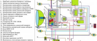
Rice. 5.2. Electrical diagram of the motorcycle IZH-Planet 5-01:
1, 13, 29, 34, 39 - lamps A12-21-3 of the motorcycle and side trailer turn signal lamp; 2, 14, 28, 33, 38 - direction indicator lights; 3- control lamp A12-1 “D. light"; 4- lamp A12-4 parking light; 5- headlight; 6- lamp A12-45-40 high-low beam headlights; 7 - indicator lamp AMN 12-3-1 direction indicator; 8- control lamp A12-1 “neutral”; - 9- control lamp A12 “oil”; 10- lamp AMN12-3-1 for speedometer lighting; 11- speedometer; 12- instrument panel; 15 - combination switch; 16- ignition switch; 17- brake light switch, front wheel brake; 18- turn signal switch; 19 - sound signal; 20 - spark plug; 21 - spark plug tip; 22- ignition coil; 27-switch; 24- lamp A12-5 of the side trailer lamp; 25- front side trailer lamp; 26- generator; 27-sensor; 30- rear side trailer lamp; 31- lamp A12-5 for side trailer dimensions; 32- lamp A12-21-3 side trailer brake light; 35- lamp A12-21-4 motorcycle brake light; 36- motorcycle rear lamp; 37- lamp A12-5 rear marker of a motorcycle; 40- brake light switch, rear wheel brake; 41- rectifier-voltage regulator; 42- fuse; 43- rechargeable battery; 44- valve-oil supply sensor; 45 - neutral lamp switch; 46- alarm switch
Wire color designation
: G - blue; F - yellow; 3 - green; K - red; Kch - brown; O - orange; P - pink; C - gray; F purple; H - black Note.
On a motorcycle with a side trailer, the rear side trailer light is connected to the connector of the green and red wires going to the rear light of the motorcycle (shown with a dotted line in the diagram).
The operation and activation of all systems is controlled by the corresponding switches and switches. The supply voltage is supplied to all consumers through the ignition switch (lock).
Since 1995, on IZh motorcycles, instead of switch 14.3704, ignition switch 7.107-3704, which has 8 connection terminals, has been used. In this case, on motorcycles Planet 5, Jupiter 5 (except for Planet 5-01 and Planet 6), terminals 1 and 2 are not used, the wire from terminal 1 of switch 14.3704 (according to the electrical diagram) is connected to terminal 3 of switch 7.107-3704, from terminal 2 to terminal 5, from terminal 3 to terminal 6, from terminal 5 to terminal 7, from terminal 6 to terminal 8, respectively.
The battery and electricity consumers on motorcycles IZhP5, IZhYu5 are connected in parallel to terminal X8 of the rectifier-regulator, that is, to the common point of the regulated voltage of the generator set. This connection via separate circuits improves the conditions for charging the battery when operating motorcycles. The battery circuit is protected by a fuse rated for a maximum current of 10 A. The fuse is located in the left tool box.
The ignition system of both motorcycle models is battery-based, contact with mechanical breakers.
The system is equipped with an engine kill switch located in the right combination switch.
The main difference in the electrical equipment of motorcycles is determined by the number of ignition coils, the design of the breakers and the engine emergency switch circuit.
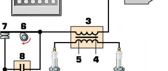
On the Izh-Planet 5 motorcycle, equipped with a single-cylinder engine, one ignition coil and a G36M1 breaker are installed. Sat. 5 (Fig. 5.3, 5.12). The engine kill switch is connected to the negative terminal of the ignition coil and to the ground of the motorcycle. When the engine is stopped by the emergency switch, the low-voltage circuit of the ignition coil (primary winding) is connected to ground, and sparking stops.
On Izh-Jupiter motorcycles equipped with a two-cylinder engine, two ignition coils and a G36M2 breaker are installed. Sat.Z with two pairs of contacts (Fig. 5.4, 5.13). The engine kill switch is connected to the negative terminals of the ignition coils. When the engine is stopped by the emergency switch, the ignition switches are electrically connected to each other, and sparking stops. The emergency switch on Jupiter functions normally when the gaps between the breaker contacts are within 0.4...0.6 mm. With gaps of 0.7 mm or more, stopping the engine with an emergency switch is impossible, since electrical communication between the breakers is not ensured in this case.
To connect electrical equipment units into a general circuit on motorcycles, flexible low-voltage wires of the PGVA type with a conductor cross-section of 0.75, 1.0 and 2.5 mm in polyvinyl chloride insulation in the following 10 colors are used: blue, yellow, green, brown, red, orange, pink, gray, purple, black. Wires are connected to electrical equipment units using automotive type socket connectors, single plugs and screw terminal lugs.
To connect the electrical equipment of side trailers to the on-board network of motorcycles, single plug connections are provided, the connectors of which include the wires of the side trailer lights.
A special feature of the wiring diagram of the Planet 5-01, Planet 6 motorcycles with a permanent magnet generator is the ignition system, which ensures engine operation independently of the battery (Fig. 5.2). The ignition switch on motorcycles IZHP5-01, IZHP6 ensures the inclusion of electrical equipment according to table. 5.2. A feature of the electrical circuit of the IZHP5-01 motorcycle is the presence of additional devices: a sensor and an ignition switch, as well as an extremely simplified diagram of the ignition system: a generator with a sensor - a switch - a coil - a spark plug. The ignition switch has 8 connection terminals (Fig. 5.14).
The IZ Jupiter 5 wiring diagram seems to be quite simple before the first repair. In fact, understanding the intricacies of wires is quite difficult, especially if you have to change a large piece or the entire wiring. For these purposes, it is necessary to know or have in front of you a detailed diagram and, guided by it, repair the motorcycle. Below, you will find out what the IZ Jupiter wiring diagram looks like, how to improve it, and other useful information on the topic.
Electrical equipment IZH Planet 5
Wiring for IZH Planet 5 includes:
- generator;
- battery;
- ignition system;
- headlights;
- control devices;
- switching elements.
Video: review of IZH Planet 5 wiring
Taken by user Agronom.
Generator
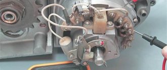
IZ Planet 5 generator design:
- voltage regulator with rectifier BPV-14-10 - 1;
- rotor - 2;
- stator with windings - 3;
- current collector brushes - 4;
- ignition system cam (battery) - 5;
- ignition system contact unit - 6.
The generator converts the mechanical energy of a gasoline engine into electrical energy, which charges the battery. Alternating current is generated by 3 windings and fed to a rectifier, which converts it into direct current. An additional coil is used as an exciter.
Photo gallery: IZH Planet 5 generator and its design
Generator IZH Planet 5 Generator design
Battery
To supply all components, a low-power energy storage device of 12 volts is required, since IZH Planet 5 does not have a starter. The purpose of a lead-acid battery is only to supply voltage to the ignition system and the excitation winding of the generator during startup.
Battery
Ignition system
In IZH Planet 5, the ignition coil converts low-voltage voltage into high-voltage and transmits it to the spark plug. That, in turn, is responsible for the spark that detonates the fuel. To ensure that detonation occurs only in the desired piston position, there is an ignition chopper.
Ignition system
From the factory, this model is equipped with a classic ignition system, which requires periodic cleaning of the breaker contacts and adjusting the gap between them.
Installing a contactless SG on a motorcycle gives:
- timely powerful sparking;
- reduction of vibration levels;
- reduction in fuel consumption.
Control devices
The following control devices are installed on the motorcycle:
- tachometer, on which there are indicator lights for the headlights and turns;
- speedometer showing total and daily mileage;
- power engine temperature indicator;
- voltmeter.
Control devices
Headlight and dashboard lamps
Conventional incandescent lamps are installed as lighting equipment and to illuminate the dashboard. Switching elements are responsible for supplying electricity from the battery to the lamps.
The headlight circuit includes lamps:
- headlight (35 watt);
- parking light headlights (4 W);
- control - blue light (2 watts);
- rear brake light (15 W).
Headlight
Switching elements
Switching elements are various types of switches that close or open an electrical circuit. They can be activated using keys on the dashboard (for example, turn signals) or by sensors.
In IZH Planet 5, the switching elements include:
- turn switches;
- signal key;
- switches for low/high beam headlights;
- neutral sensor;
- egnition lock;
- foot and hand brake sensors.
Wiring diagram IZH Planet 5
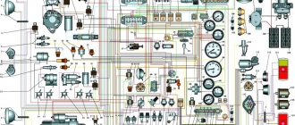
Detailed color wiring diagram for motorcycle IZH Planet 5
Explanations for the diagram
The numbers on the electrical diagram correspond to the following elements:
- Light switch, dimensions/low.
- Light switch, direction indicators and horn buttons.
- Front turn signals.
- Instrument panel lighting.
- Indicator lamp for generator operation.
- Oil pump operation indicator.
- A light indicating the operation of the neutral gear in the gearbox.
- Direction indicators.
- High beam headlight indicator.
- Front parking light bulb.
- Headlight lamp.
- Sound signal.
- Hall Sensor.
- Generator.
- Egnition lock.
- Turn signal interrupter relay.
- Neutral gear warning lamp sensor.
- Block BPV 14-10.
- Switch.
- Battery.
- Fuse.
- Relay block.
- Ignition coil.
- Foot brake light sensor.
- Rear direction indicators.
- Rear light with lamps.
Description of the symbols for the terminals on the rectifier-regulator block BPV 14-10:
- –x1 — “minus” of the generator excitation winding;
- –x2 — “minus” of the battery (“ground”);
- x2 - “positive” wire to the control lamp of the instrument panel;
- x3 - “positive” wire to the panel indicator;
- x4, x5, x7 - phases of the stator winding;
- x8 - “plus” of the battery.
Distinctive features of electrical equipment
The wiring diagram used on IZ Planet 3 was traditional, and the main parameters of the electrical equipment are presented below in the table.
Lighting devices
The following lighting devices were installed on the IZH Planet 3 motorcycle:
- Left and right direction indicators with A6-6 lamps;
- Turn signal switch P201;
- Turn signal relay RS-419;
- Brake light bulbs A6-15;
- Side light bulbs A6-2;
- Light mode switch with sound signal button P200;
- Transmission position sensor (neutral) with warning lamp A6 0.25;
- Headlight lamp A6-32+32;
- Indicator lamp A6 0.25 generator operation;
- Side light lamp A6-2 (front);
- Speedometer scale illumination lamp A6-1;
Attention! For lovers of the “original” and authenticity, the photo below shows the “native” black and white wiring diagram of IZH Planet 3 with a breakdown of all the elements.
Note! The standard wiring of the IZH Planet 3 provided for disconnecting the sidecar for operating the motorcycle without it in a two-wheeled version. At the same time, the connecting terminals required care.
In the presented video you can watch the repair of an old motorcycle, which received a new life in capable hands. According to the author of the video, complete restoration cost him the equivalent of $130. Moreover, he did most of the work with his own hands.
Maintenance
The owner can independently perform some maintenance procedures:
- check the motorcycle generator if the battery loses charge;
- set the gap between the breaker contacts;
- adjust the quality of the sound signal.
The need to inspect and adjust the wiring arises if:
- the motorcycle moves in the rain for a long time, as this causes oxidation of the contacts;
- a motorcyclist rides in an area with a lot of vegetation that damages wiring;
- The driver rides in snow in winter, which can stick to electrical wiring parts and damage them.
Self-check of the Planet 5 motorcycle generator in case of loss of charge
The cause of loss of charge in the IZH Planet 5 battery is most often a breakdown of the generator.
To check it yourself you need:
- multimeter device;
- straight screwdriver.
Step-by-step instruction
The following steps must be followed:
- Disconnect the wires from the battery and remove the generator cover.
- Disconnect the top 5 wires from the generator, first unscrewing their fastenings. In order not to mix up the wires during assembly, it is worth marking them.
- Measure the winding resistance using a multimeter in ohmmeter mode. To do this, you need to touch the body with one probe, and the other should be connected in turn to the 3 wires of the winding. There should be no short circuits, as indicated by the inscription on the multimeter screen.
- Test the resistance between the stator contacts: you need to touch them one by one with the multimeter probes. The value on the screen should be 8 ohms.
The presence of a short circuit in the 3rd stage or a discrepancy in the indicators in the 4th will indicate problems with the generator.
Photo gallery: stages of checking the IZH Planet 5 generator in case of loss of charge in pictures
Stage No. 1. Photo disconnection of the generator from the battery Stage No. 2. Disconnecting the wires from the generator Stage No. 3. Measuring the resistance of the windings Stage No. 4. Testing the resistance
How to correctly set the gap between the contacts of the breaker?
In order to set the gap between the breaker contacts, you will need:
- straight screwdriver;
- wrench 10;
- candle key;
- probe 0.4 mm thick (+/– 0.05 mm).
- Place the motorcycle on a stand and place the gearbox in neutral.
- Remove the right crankcase cover and unscrew the spark plug.
- Using a 10mm wrench, grab the generator rotor mounting bolt and turn the crankshaft to a position where the contacts are as far apart as possible.
- Loosen the screw securing the contact.
- Place the probe between the contacts and adjust the tightening of the eccentric screw until the probe passes the contacts with little resistance.
- Tighten the contact fixing screw.
While easily fixing mechanical failures, motorcyclists experience difficulties if the electrics fail. It’s completely in vain, the wiring diagram of the planet Izh 5 is not complicated, it’s easy to figure out.
There is no need to have special stands and equipment for repairs. A minimum knowledge of electrical engineering and a simple avometer (tester) is enough; even often you can get by with just a test lamp.
We will tell you in more detail about the main electrical wiring components and possible malfunctions. The Izh Planet wiring diagram makes it easy to find a broken wire or damaged insulation (for example, a bad contact always gets hot).
But pay special attention to the fact that the electrical circuit is designed not only for 12 volts, there is also a high-voltage cable (connecting the coil and the spark plug), which cannot be checked with a regular ohmmeter.
In this case, we look to see if there is a spark at the coil output and at the output at the spark plug contact. Let's take a closer look at the main wiring components of the Izh Planet.
Generator
The heart is the generator (sometimes called a magneto, but they were never used on Izh Planet). Three windings produce alternating current. For excitation, an additional coil is used instead of a permanent magnet. Therefore, it is impossible to jump start a motorcycle with a completely dead or missing battery.
A diode bridge for current rectification and a voltage regulator assembled in one unit are mounted on the Izh Planet 5 generator (they are not even highlighted in the Izh Planet wiring diagram manuals).
Possible breakdowns in this unit:
- It is checked by measuring their resistance of current-carrying conductors and insulation. If the generator is damaged, it will become noticeably hot.
- — the output voltage will differ significantly from the nominal level or be absent.
- Although the electrical circuit includes short circuit protection, it happens that the automation does not work and most often the output transistor burns out.
Differences from the second Planet
For many modern citizens, the information that domestic motorcycle manufacturers worked tirelessly to improve their models in an era of total shortages may come as a surprise.
Note! The fact takes place, moreover, it is supported by official documents, in particular 1970N04P16-17 - this is the outgoing number of the factory newsletter, which described the changes made.
The new generation motorcycle received:
- Direction indicator lights are a first in domestic practice;
- Semiconductor relay for controlling direction indicators (installed in the headlight);
- New size of wheels and tires (3.50x18 versus previous - 3.25x19);
- New brand increased capacity battery (old one on IZH Planet 2 - ZMT-6);
- And, of course, more engine power. The power unit now developed 18 hp.
Modifications
But the creator engineers did not stop there and, having released the five-millionth car from the production line, presented a modification of the IZH Planet 3-01.
Among the innovations it should be noted:
- Rear passenger footrests;
- Roll bars;
- Rearview mirror;
- New steering wheel design.
For reference: The buyer paid for the changes out of his own pocket. In particular, the price for IZH Planet 3-01 was 750 rubles, the version with a stroller was 1140, and the “rural version” was even more expensive. Fortunately, care instructions were included with purchase, which made maintenance easier.
Battery
The battery in the motorcycle is low-power. The motorcycle does not have a starter, so its task is only to supply voltage to the ignition system and the generator excitation winding during starting. Thanks to the battery, designed for 12 volts, a stable start of the fifth Planet is ensured; up to the third model, the wiring was 6 volt, and the ignition was not always clear.
Possible battery malfunctions:
- - housings, plates, leakage of electrolyte.
- - determined by measurements using a hydrometer.
- - detected by measuring resistance.
- minus not on the body (frame) of the motorcycle - all the electronics will not work.
Installation of BSZ
Contactless ignition system - this element has become so popular that it rightfully occupies the place of the most popular improvement to the standard ignition circuit. From the factory, the IZ Jupiter 5 wiring model is equipped with a contact ignition system. It is unable to hold the ignition angle advance settings for a long time, has failures in operation and low accuracy. The disadvantages of this system can be listed for a very long time, so owners switch to electronic ignition, thereby increasing power, reducing consumption and getting a flat torque and power curve.
Ignition system
The ignition chopper is used to ignite a spark at a certain point in the piston stroke. In early modifications of the electrical wiring of Izh Planet 5, contact was mounted, later electronic.
The main malfunctions of this unit:
- Burning of breaker contacts is determined visually.
- Failure of a sensor or switch elements - the easiest way to detect it is to use the method of installing a known-good unit. The lubrication system sensor valve is also checked using the same method.
- An incorrectly set ignition timing is visible from the fuzzy operation of the engine. It can be eliminated by adjustment using special probes.
The ignition coil increases the voltage to several kilovolts so that the discharge can ignite a spark at the spark plug electrodes. The secondary winding is made of a fairly thin wire; most often it burns out. Although a breakdown between the turns or onto the housing is also possible. The same troubles can (but less often) happen to the primary circuit. Everything is revealed using resistance measurements.
Switching elements.
These include switches (high-low, turns, engine stop, etc.) as well as brake and neutral sensors and the ignition switch. You can easily “ring” them with a tester, finding out which contact group is not working.
Switching also includes the Izh electronic turn signal relay. Its malfunction is visible by the absence of interruption or no voltage supply to the turn signals.
As can be seen from all of the above, the wiring on Izh Planet is without any special secrets or complex elements, all its parts are easily diagnosed and repairs should not cause difficulties.
Now we advise you to watch the video, which shows in detail and clearly the assembly of the Izh Planet 5 circuit.
“Planet-Sport” is the first Izhevsk motorcycle with 12-volt electrical equipment, which meets all modern (as of 1982) requirements for this system.
(click on the picture to enlarge)
Wiring Problems
Practice shows that if the motorcycle was stored in a dry garage and was not subjected to dubious alterations, then the Jupiter 5 wiring diagram lasts a very long time. From time to time you need to change some consumables, such as lamps and ignition coils, but otherwise it functions quite stably. However, this is not always the case and problems do occur, for example:
- wire breaks;
- electrical circuit short-circuit;
- failure of their individual branches of the circuit;
- weak light from incandescent lamps;
- incorrect operation of indicators;
- misfire;
- reduction in engine power;
- complete failure of the system.
The problems described above can arise both due to natural wear and tear of wiring elements, and after incompetent intervention in the circuit. There is no universal solution to the problem in this case, and in order to find out what caused the breakdown, you should be patient and have some basic knowledge of the technical part of the motorcycle. First of all, you should get a multimeter or assemble a primitive network indicator using a 12-volt light bulb to “ring” the wiring for breaks. Having found a circuit node that is not working correctly or a wiring break, it will need to be eliminated, the network’s functionality re-checked, and so on, until operation is completely restored.
Electrical circuit diagram of the IZH Planet Sport motorcycle
I — parking light lamp; 2 — main light lamp; 3 — neutral control lamp; 4 - resistor; 5 — oil pressure control lamp; 6 — direction indicator relay; 7 — diode block (isolation); 8 — lamp for illuminating the speedometer scale; 9 — ignition switch; 10 — front direction indicator lights; II - headlight switch and emergency ignition switch; 12 — handbrake brake light switch; 13 — relay-regulator; 14 — neutral lamp switch; 15 — high beam control lamp; 16 — turn signal control lamp; 17 — lamp for monitoring generator operation; 18 — sound signal; 19 — light switch and direction indicators, horn switch; 20 — spark plug; 21 — ignition coil; 22 — foot brake brake light switch; 23 - generator; 24 - battery; 25 - fuse; 26 - rectifier; 27 — oil pressure sensor; 28 — rear direction indicator lights; 29 — rear light.
While improving the car, the plant made a number of changes to it. In particular, the fixation and clarity of operation of the IZH P101 and IZH P102 switches and the switch on the steering wheel have been improved. The optical element in the headlight was replaced by the Soviet FG 137, and the IZH UP1 turn signal lights were replaced with standardized lights 16.3726. There are other innovations as well.
Jupiter-4 is now equipped with 12-volt equipment. The plant is also preparing for production a new Planet-Sport model, the electrical equipment of which is unified with Jupiter-4.
However, even now, Planet-Sport owners can use a number of IZH Yu-4 electrical appliances without significant modifications. These include generator 28.3701 (if it is sold without a breaker and capacitor, they can be taken from the old IZH GP1); direction indicator lights 16.3726; headlight optical element FG 137; rear light FP146; speedometer SP102; battery 6MTS-9.
To install the IZH RP2SM-10 turn signal breaker in the headlight housing, you need to make an additional bracket from a steel strip 1-1.5 mm thick and replace the plug tips with round ones. After the same modification of the tips, the combined switches IZH P101-20 and IZH P102-20 from the IZH Yu-4 motorcycle can be used on Planet-Sport. To do this, squeezing out the fixing tendrils with an awl or knitting needle, remove the plug tips. They cut them off and crimp and solder round tips on the stripped ends of the wires. At the IZH P101-20 switch, a blue outlet wire 130-150 mm long with a plug tip is soldered to the black wire.
Improvements in the electrical equipment of motorcycles and the use of new devices have naturally led to some complication of the electrical circuit. Let's get acquainted with its main elements using the example of electrical equipment of the “Planet-Sport” circuit, which is in many ways similar to the circuits of other Izhevsk motorcycles.
Ignition system
. This is perhaps the main system, because without it the motor cannot work. Let's trace and remember its electrical circuit. From the battery 24 through fuse 25 and rectifier 26, power is supplied to terminal (2) of the connecting panel in the headlight housing and then to terminal (3) of the ignition switch 9. When the key is turned to position I, the terminals (3—2—1 and 5) are closed -6). Now from terminal (1) of the lock, the current flows to terminal (5) of the connecting panel, from it to the emergency ignition switch 11, and through its closed contacts to terminal (1) of the connecting panel and then to the primary winding of the ignition coil 21 (the second end of the primary winding — terminal “—” is connected to the breaker). This turns on the motorcycle's ignition circuit.
If the engine does not run due to lack of spark at the spark plug, check whether high voltage is supplied to it. To do this, remove the wire from the cap and bring it to the edge of the cylinder with a gap of 2-3 mm. If, when the crankshaft is rotated by the kick starter, a spark does not appear between the wire and the cylinder, there is no high voltage. The reason for this is found as follows. When you turn on the ignition, use a 12-volt test light to check whether power is supplied to the “+” terminal of the ignition coil. If not, then check the entire circuit, starting from the battery. The usual cause of no voltage is loose or oxidized terminals, or a faulty fuse.
Having ensured that normal voltage appears at the “+” terminal of the ignition coil, carefully clean the breaker contacts, check and set a gap of 0.4-0.6 mm between them and adjust the initial ignition timing.
If the engine produces only isolated flashes when starting, and a white coating appears on the contacts of the breaker, it means that the capacitor has failed (rarely, but it happens).
With the correct gap, clean contacts of the breaker and a working capacitor, the reason for the lack of a spark on the spark plug may be a malfunction of its plastic cap (ground fault) or the ignition coil (it is non-separable, so it must be replaced). A poor-quality spark plug can cause engine interruptions or make it difficult to start. Signaling and lighting system
Direction indicator
. When the ignition is turned on (key in position I), electricity from the battery 24 (or rectifier 26 when the engine is running) is supplied through terminals (3 and 1) of the ignition switch 9 to terminal (5) of the connecting panel. The power wire for turn signal relay 6, horn 18 and the “positive” wire for light switch 11 located on the steering wheel are connected to it. From relay 6, power is supplied to the lights through the terminal (9) of the connecting panel and then to the turn signal switch 19. From it, through terminals (6 and 7) of the connecting panel, it goes to lights 10 and 28 turn indicators. The turn signal indicator lamp 16 is also connected to the terminals (6 and 7) of the connecting panel through the diode block 7.
The reason for the failure of direction indicators to work most often is the lack of “ground” in the lamps when their fastening to the frame is loosened, oxidation or loosening of the connections of the tips with the wires, contacts in the lamp sockets.
To speed up troubleshooting, the circuit is checked from the non-working consumer to the power source. To determine the functionality of the turn signal relay 6 without dismantling it, you must first make sure that voltage is supplied to terminal (5) of the connecting panel and that the brown wire of the relay is securely connected to ground. Then check the serviceability of the circuits going to the direction indicator lights by connecting terminal (5) with terminals (6 and 7) of the connecting panel with a separate wire. The lights on the right (terminal 6) or left side (terminal 7) and indicator lamp 16 should light up without blinking if the circuits are working. Next, disconnect the pink relay wire from terminal (9) and connect it to terminals (6 and 7) on the connection panel. If the relay is working properly, the starboard or port side lights should blink at a frequency of 60 to 120 per minute.
The relay removed from the motorcycle is checked using two A12-21-3 test lamps (each with a power of 25 W), connected in parallel. Connect the “plus” of a constant voltage of 12 volts to the red wire, the “minus” to the brown wire, and the control lamps to the pink wire. When the device is working properly, the lamps should flash at a frequency of 90 ± 30 per minute.
headlight
. It contains the main part of the wiring diagram, the turn signal relay, the neutral 3 and oil pressure indicator lamps 5, the lamp 8 that illuminates the speedometer scale, the parking light lamp 1, the head light lamp 2, the ignition switch 9 and the speedometer.
On the latest motorcycle models, the turn signal switch is mounted on the frame under the gas tank.
Let's consider the electrical circuit of the head, parking and side lights. When the ignition is turned on (key in position I), power is supplied to terminal (4) of the connecting panel, then through the contacts of the light switch 11 - to the central contact of the high-low beam switch 19. Next, through the terminals (11 and 12) of the connecting panel - to the high or low beam filament of lamp 2.
The side light in the headlight (lamp 1) and in the rear lamp 29 lights up when switch 11 is activated and current flows through contacts (5 and 6) of ignition switch 9.
If the ignition key is turned to position II (parking), then these lamps receive power through its contacts (3 and 5) regardless of the position of the switches on the steering wheel.
Lamps that glow dimly when the engine is not running indicate that the battery is not fully charged. If this is observed in all modes of engine operation, it means that the voltage in the lamp power circuit drops significantly. In this case, check the electrical connections of the power and ground wires, clean and tighten the screw and plug connectors, contacts in the headlight and flashlight lamp sockets. Check the serviceability and reliability of the contacts in the switches and fuse.
Since the motorcycle is constantly being improved during the production process and its electrical circuit is changing, it is advisable to include the differences in your motorcycle in the circuit printed here so that, using it, you can always easily and quickly find the desired circuit and determine the malfunction.
V. SAMOILOV, engineer Izhevsk
The road version of the IZH Planet 5 motorcycle differed favorably from other domestic analogues by the use of an oil pump, which made it possible to abandon the scheme for pre-mixing fuel with oil.
In addition, subsequent modifications were distinguished by their contactless ignition system, independent of the battery, and modified kinematics.
This allowed:
- To set the motorcycle in motion “from the pusher” - by turning on the ignition, the owner engaged second gear and, using his own efforts, pushing the motorcycle forward, started the engine;
- Operation without a battery was possible during daylight hours (a battery was still required for the side lights and headlights to operate).
According to industry norm, the motorcycle had an alphanumeric index:
- IZH 7.107-010 – basic model;
- IZH 7.107-020 was already equipped with a new lubrication system and improved front axle suspension. In addition, the wiring diagram of the IZH Planet 5 motorcycle had a contactless ignition system, independent of the battery;
- IZH 7.107-030 was equipped with a spring-hydraulic shock absorber and a redesigned rear wheel brake drive;
- IZH 7.107-040 was produced with modified kinematics and a modified front wheel brake. The wiring diagram on IZH Planet 5 remained contactless until 2008.
In addition, a side trailer (sidecar) or a universal cargo platform (without a seat) could be attached to the motorcycle.
Motorcycle Features
The IZH Plante 5 motorcycle has the original name IZH 7.107. Just like the IZH 6, it belongs to the middle class of motor vehicles, designed for movement on roads with any surface. The main feature is the use of an oil pump; when refueling there is no need to add oil to the tank, as well as a contactless ignition system that operates independently of the battery.
It became possible to start a motorcycle from a pusher. To do this, you need to turn on the ignition, second gear and, when pushing the bike forward, the engine starts. True, without a battery, operation is possible only during daylight hours.
The Fifth Planet can be equipped with a cargo trailer and a passenger stroller. To reduce the clutch release effort, the bike has a clutch consisting of 7 pairs of discs. Vibration dampers are installed on the cylinder ribs. An important feature of this series is the presence of hydropneumatic suspension with disc brakes, which contributed to a smooth ride. The power is 22 horsepower, the maximum possible speed is 120 km/h. The volume of the two-stroke single-cylinder engine is 346 cm3. The power unit has good traction at low speeds.
Electrical equipment IZH Planet 5
The motorcycle uses 12-volt electrical equipment. The electrical wiring of the IZH Planet 5 motorcycle is single-wire, the role of the negative wire is performed by a metal frame.
Among the main components are:
- Power supplies;
- Ignition system;
- Headlight;
- Side lighting and turns.
For reference: as is customary in auto and motorcycle construction, modification of components and assemblies allows you to reduce the cost of products. For consumers, the advantage is that the price is low and a number of parts are interchangeable.
Generator
The motorcycle is equipped with a three-phase alternating current generator with an electromagnetic excitation circuit.
The principle of its operation is as follows:
- Electric current from the windings located on the stator is supplied to the rectifier;
- It converts it to direct current;
- And supplies it to consumers through the ignition switch.
The instructions provided include the following items:
- Voltage regulator with rectifier BPV-14-10;
- Generator rotor;
- Generator stator with windings;
- Current collector brushes;
- Ignition system cam (battery);
- Ignition system contact unit
For reference: on three-phase generators of the IZH Planet 5 motorcycle, the windings are connected according to a “star” or “delta” circuit. The rectifier is installed as a separate unit, and the IZH Planet 5 electrical wiring is connected to it.
Headlight
For reference: with such a generator, IZH Planet 5 did not need an external current source when starting the engine. Therefore, the battery was not included in the electrical equipment.
The head light circuit includes:
- headlight lamp (35W);
- blue indicator lamp (2W);
- headlight parking light (4W);
- rear brake light lamp (15W).
Control devices
The following control devices are installed on the motorcycle:
- speedometer with daily and total mileage counters;
- tachometer with indicator lamps for direction indicators and headlights;
- engine temperature indicator;
- voltmeter.
How to improve the standard electrical system?
As we have already said, standard wiring does not cause any particular complaints due to its solidity, ability to withstand oxides and rust at the joints, without losing functionality. That is why complete replacement of wiring is a questionable procedure, but upgrading individual parts makes sense. By individual parts, we mean such functional elements as head lights, indicators, turn and stop lamps, ignition system, generator. Let's talk about each of the elements separately.
Maintenance Features
Often during operation it is necessary to correctly set the gap between the contacts of the breaker. To do this, you need tools and a diagram to see which elements need to be dismantled.
The algorithm of actions is as follows:
- place the motorcycle on the stand;
- turn on neutral;
- unscrew the spark plug from the cylinder;
- remove the engine crankcase cover;
- turn the crankshaft until the contacts are as open as possible;
- using a screwdriver, loosen the locking screw;
- using a special feeler gauge, set the gap to 0.35-0.45 mm and fix it with a screw;
- we collect everything in reverse sequence;
- turn on the ignition and start the engine. Its stable operation at idle indicates that the adjustment has been correctly performed.
In general, all the wiring of IZH Planet 5 is very easy to do with your own hands.
The need for such work often arises when operating a motorcycle:
- in wet weather, driving in the rain for a long time (oxidation or dampness of electrical contacts);
- when traveling over rough terrain, replete with vegetation and bushes (mechanical damage to wiring);
- when used in winter (snow and slush stick to the wires and can damage them).
Often the sound signal suffers during operation. Its malfunctions manifest themselves in the form of deterioration in sound quality.
To restore its functionality, you must perform the following procedure:
- loosen the locknut using an open-end wrench;
- turn on the ignition;
- press the button to turn on the sound signal;
- use a screwdriver to adjust the tone;
- repeat the procedure until we get a clear and loud sound;
- tighten the control nut.
Conclusions: we are confident that this article will help you in servicing motorcycles of the IZH family (see also the article about). Both the attached diagrams and description will help you avoid making mistakes during operation.
The wiring diagram of IZH Planet 5 has a simple design: a single-wire DC network is provided by a 12-volt battery, which is charged by a generator with a power of 100–140 watts. The role of the negative wire in the electrical circuit is played by the metal frame, and since the rest of the wiring has a positive charge, their short circuit is often the main cause of the malfunction.
[Hide]
Major problem with motorcycle wiring
On IZ Jupiter 5, the wiring had a large number of contact terminals. Therefore, the main cause of malfunctions in the electrical circuit was a violation of the integrity of the connections. This led to such moments as: there is no charging for the battery, the generator does not provide the necessary 12-volt voltage to the system, the switch is not able to generate the necessary charge for the ignition coil, loss of functionality of all lighting devices, and a number of others.
The cause of loss of connection in the terminals was contamination and oxidation of the contacts. This was especially true for motorcycles produced at the beginning of mass production. The main way to solve this problem was to exclude these terminals from the IZ Jupiter 5 wiring.
To do this, we used soldering the wires directly to each other (by analogy with), as well as sealing the terminals on the supply wires to the following main elements:
- battery;
- generator;
- coil and spark plug;
- switch;
- lighting devices.
This increased the reliability of the connections and, as a result, ensured the operability of the specified parts, and also made it possible to turn on charging for the battery in order to subsequently confidently start the engine of the IZH Jupiter 5 motorcycle.
Electrical equipment IZH Planet 5
Wiring for IZH Planet 5 includes:
- generator;
- battery;
- ignition system;
- headlights;
- control devices;
- switching elements.
Video: review of IZH Planet 5 wiring
Taken by user Agronom.
Generator
IZ Planet 5 generator design:
- voltage regulator with rectifier BPV-14-10 - 1;
- rotor - 2;
- stator with windings - 3;
- current collector brushes - 4;
- ignition system cam (battery) - 5;
- ignition system contact unit - 6.
The generator converts the mechanical energy of a gasoline engine into electrical energy, which charges the battery. Alternating current is generated by 3 windings and fed to a rectifier, which converts it into direct current. An additional coil is used as an exciter.
Photo gallery: IZH Planet 5 generator and its design
Generator IZH Planet 5
Generator device
Battery
To supply all components, a low-power energy storage device of 12 volts is required, since IZH Planet 5 does not have a starter. The purpose of a lead-acid battery is only to supply voltage to the ignition system and the excitation winding of the generator during startup.
Battery
Ignition system
In IZH Planet 5, the ignition coil converts low-voltage voltage into high-voltage and transmits it to the spark plug. That, in turn, is responsible for the spark that detonates the fuel. To ensure that detonation occurs only in the desired piston position, there is an ignition chopper.
Ignition system
From the factory, this model is equipped with a classic ignition system, which requires periodic cleaning of the breaker contacts and adjusting the gap between them.
Installing a contactless SG on a motorcycle gives:
- timely powerful sparking;
- reduction of vibration levels;
- reduction in fuel consumption.
Control devices
The following control devices are installed on the motorcycle:
- tachometer, on which there are indicator lights for the headlights and turns;
- speedometer showing total and daily mileage;
- power engine temperature indicator;
- voltmeter.
Control devices
Headlight and dashboard lamps
Conventional incandescent lamps are installed as lighting equipment and to illuminate the dashboard. Switching elements are responsible for supplying electricity from the battery to the lamps.
The headlight circuit includes lamps:
- headlight (35 watt);
- parking light headlights (4 W);
- control - blue light (2 watts);
- rear brake light (15 W).
Headlight
Switching elements
Switching elements are various types of switches that close or open an electrical circuit. They can be activated using keys on the dashboard (for example, turn signals) or by sensors.
In IZH Planet 5, the switching elements include:
- turn switches;
- signal key;
- switches for low/high beam headlights;
- neutral sensor;
- egnition lock;
- foot and hand brake sensors.
Wiring diagram IZH Planet 5
Detailed color wiring diagram for motorcycle IZH Planet 5
Explanations for the diagram
The numbers on the electrical diagram correspond to the following elements:
- Light switch, dimensions/low.
- Light switch, direction indicators and horn buttons.
- Front turn signals.
- Instrument panel lighting.
- Indicator lamp for generator operation.
- Oil pump operation indicator.
- A light indicating the operation of the neutral gear in the gearbox.
- Direction indicators.
- High beam headlight indicator.
- Front parking light bulb.
- Headlight lamp.
- Sound signal.
- Hall Sensor.
- Generator.
- Egnition lock.
- Turn signal interrupter relay.
- Neutral gear warning lamp sensor.
- Block BPV 14-10.
- Switch.
- Battery.
- Fuse.
- Relay block.
- Ignition coil.
- Foot brake light sensor.
- Rear direction indicators.
- Rear light with lamps.
Description of the symbols for the terminals on the rectifier-regulator block BPV 14-10:
- –x1 — “minus” of the generator excitation winding;
- –x2 — “minus” of the battery (“ground”);
- x2 - “positive” wire to the control lamp of the instrument panel;
- x3 - “positive” wire to the panel indicator;
- x4, x5, x7 - phases of the stator winding;
- x8 - “plus” of the battery.
Maintenance
The owner can independently perform some maintenance procedures:
- check the motorcycle generator if the battery loses charge;
- set the gap between the breaker contacts;
- adjust the quality of the sound signal.
The need to inspect and adjust the wiring arises if:
- the motorcycle moves in the rain for a long time, as this causes oxidation of the contacts;
- a motorcyclist rides in an area with a lot of vegetation that damages wiring;
- The driver rides in snow in winter, which can stick to electrical wiring parts and damage them.
Self-check of the Planet 5 motorcycle generator in case of loss of charge
The cause of loss of charge in the IZH Planet 5 battery is most often a breakdown of the generator.
To check it yourself you need:
- multimeter device;
- straight screwdriver.
Step-by-step instruction
The following steps must be followed:
- Disconnect the wires from the battery and remove the generator cover.
- Disconnect the top 5 wires from the generator, first unscrewing their fastenings. In order not to mix up the wires during assembly, it is worth marking them.
- Measure the winding resistance using a multimeter in ohmmeter mode. To do this, you need to touch the body with one probe, and the other should be connected in turn to the 3 wires of the winding. There should be no short circuits, as indicated by the inscription on the multimeter screen.
- Test the resistance between the stator contacts: you need to touch them one by one with the multimeter probes. The value on the screen should be 8 ohms.
The presence of a short circuit in the 3rd stage or a discrepancy in the indicators in the 4th will indicate problems with the generator.
Photo gallery: stages of checking the IZH Planet 5 generator in case of loss of charge in pictures
Stage No. 1. Photo disconnecting the generator from the battery
Stage No. 2. Disconnecting the wires from the generator
Stage No. 3. Measuring winding resistance
Stage No. 4. Resistance testing
How to correctly set the gap between the contacts of the breaker?
In order to set the gap between the breaker contacts, you will need:
- straight screwdriver;
- wrench 10;
- candle key;
- probe 0.4 mm thick (+/– 0.05 mm).
- Place the motorcycle on a stand and place the gearbox in neutral.
- Remove the right crankcase cover and unscrew the spark plug.
- Using a 10mm wrench, grab the generator rotor mounting bolt and turn the crankshaft to a position where the contacts are as far apart as possible.
- Loosen the screw securing the contact.
- Place the probe between the contacts and adjust the tightening of the eccentric screw until the probe passes the contacts with little resistance.
- Tighten the contact fixing screw.