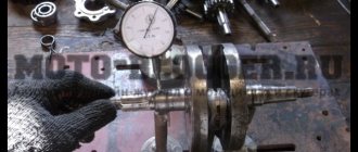
Turn the crankshaft counterclockwise as slowly as possible and pull the piece of paper at the same time. Due to this action, the piston moves, transmitting torque to the flywheel.
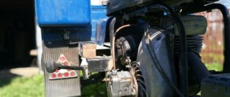
Thirdly, the scooter's headlights are supplied with the current needed at night, and the brake lights and turns are also supplied with electricity. Obe3obPasha One comment Electrical connection diagrams are usually quite complex and require special skills in order to understand the wires and the purpose of a particular element. SUBSCRIBER'S ANT→CH2: Brakes and electrics (final) The author placed all other modernization in a special box attached to the side of the scooter (Fig. Contacts Modernization of electrical equipment of the cargo scooter Ant-2 Today, fuel saving is relevant, as is the use of small vehicles in agriculture and dacha farming. So, how to set the ignition on an Ant scooter: Remove the spark plug and set the piston to top dead center beyond TDC.
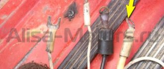
The ignition coil should be installed closer to the spark plug. Those who are already tired of suffering with the dynamo starter will understand me
The author placed all the rest of the modernization in a special box attached to the side of the scooter (Fig.
But it has the most necessary things, and the connection diagram will help you figure out the breakdown or configure the wiring. setting the magneto to maximum spark
Electrical circuit of the motor scooter Ant 2M
The electrical wiring of the Ant 2 and 2M scooter (prototype – Tulitsa 2) is located at the bottom of the scooter.
The cargo-passenger version is slightly different in appearance and electrical equipment. A more detailed power supply diagram of Ant 2M allows you to repair and tune the electrical equipment of the scooter. Download the electrical diagram of the Ant 2M scooter:
- Direction indicators
- headlight
- Indicator light (red) for dynastarter operation in generator mode
- Indicator lamp (green) for neutral activation
- Indicator lamp (orange) for direction indicator operation
- Indicator lamp (blue) for turning on the high beam headlights and the speedometer scale illumination lamp
- Sound signal
- Light breaker relay
- Side light switch
- Ignition switch and handbrake brake switch
- Switch for high/low beam and direction indicators
- Relay regulator
- Dynastarter
- Day/night switch with emergency engine shutdown
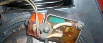
- Breaker
- Circuit breakers
- Capacitor
- Ignition coil
- Spark plug
- Neutral warning lamp switch
- Rechargeable batteries ZMTR-10
- Foot Brake Light Switch
- Rear light with brake light
The dynostarter as a device is as far from complete perfection as our VAZ plant is from the premium segment. But if at least once a season you carry out competent maintenance of the collector unit, switching equipment, and battery, then with all its inherent shortcomings, the dyno starter can last a very, very long time, up to 30,000 km, or even more.
Terminals
- The letter “B” indicates the battery connection terminal
- The letter "P" indicates the starter relay terminal
- The letter "C" indicates the starter terminal
- The letter “Ш” indicates the terminal of the shunt winding
- The letter "YaSH" designates the terminal of the shunt and armature winding
Electrical circuit of the motor scooter Ant TG 200
Installation of wiring, amplifier for the audio system in the Lada Priora
For the most part, the circuit may be needed due to a malfunction of the basic elements of movement.
How to set the ignition on an Ant scooter in 5 simple steps? Insert a rod through the hole from which the spark plug was removed and press it against the piston head. The final reason for using the diagram below is to check the flywheel, which receives torque when the piston moves. How to set the ignition on an Ant scooter in 5 simple steps? Thirdly, the scooter's headlights are supplied with the current needed at night, and the brake lights and turns are also supplied with electricity. The disadvantages of this solution include increased requirements for the cleanliness of contacts, since oil, dirt and dust caught between the contacts no longer burn out, as was the case with a conventional ignition system.
All you need is very thin paper, a narrow rod and a set of keys. When the paper is released when the piston is lowered to the depth of the mark made, the ignition will be set correctly. Since the spark plug voltage will increase from 17 to
But it has the most necessary things, and the connection diagram will help you figure out the breakdown or configure the wiring. When the paper is released when the piston is lowered to the depth of the mark made, the ignition will be set correctly. Supplying current to lighting devices and signal signs, turn signals, parking lights, brake lights. Electrical circuit of an Ant scooter, electrical equipment. Electrical circuit of an Ant scooter. Electrical equipment. Electrical equipment of an Ant scooter is used mainly in three areas.
Recent Entries
The electrical equipment of the Ant scooter is securely mounted on the body of the scooter and has good insulation, so the likelihood of a short circuit is negligible. Due to this action, the piston moves, transmitting torque to the flywheel. Insert a rod through the hole from which the spark plug was removed and press it against the piston head. For the most part, the Ant motorcycle is designed to transport large loads, so it was not equipped with special lighting parts. But the Ant motorcycle is quite simple in design, so its electrical circuit is very simple. However, to find the problem, you need to keep a tester at hand. For the most part, the Ant motorcycle is designed to transport large loads, so it was not equipped with special lighting parts. Of course, for this you need to have a special tester, thanks to which you can always determine the malfunction of a particular mounting unit or part.
The Ant generator and starter are combined in one electric machine. All equipment has excellent insulation, eliminating the possibility of short circuits and harm to the driver. Place paper between them and pinch. For the most part, the circuit may be needed due to a malfunction of the basic elements of movement. Modernization of the SOVIET ANT
anthill scooter
I'll give my two cents.
First, decide what the scooter will be used for and how often it will be used. A 2000 year old is probably fine, so leave the working system alone, but put the battery at 12V/17H, go easy and start with the key. Tens of thousands of people must travel to disable a dynastarter.
As for the cam ignition, with all its shortcomings, it seems that the timing is not entirely accurate and so on. It has one big advantage - simplicity. Three details you can see and touch. Moreover, mechanics almost never surprise, which is not the case with electronics.
When problems arise, it is best to address them when they become available. Like any equipment, ants have their problems (with the dynastarter, clutch, carburetor, etc.). However, for many, this method has worked for decades with minimal care.
Well done admin Published March 25, 2011 - 16:51
The generator and starter in the same dynastar bottle remain in place, the switch is removed from the ant. An adapter is made between the shaft and the end of the crankshaft, the front panel is placed on the dynastarter housing, and a magnet is attached to it. Since the magnet will protrude, you will need to make a cutout in the hood. Were there diagrams and pictures in motorcycle magazines for 9? of the year. It was converted into a magnet and into a Voskhod generator. I liked the version with a generator better - in 20 years of operation, I changed the switch once, and that was all the maintenance.
Emil30_30 Published January 28, 2013 - 13:46
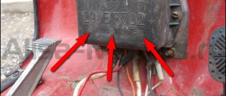
Members, I have a question for you. but in general it is possible to restore the entire enton mechanism, today I looked at the failure genes going to the coil and since I bought it second hand I would like to know if there is a relay that can be used instead of the usual one (pp-121 / 2903.3702) , since it is impossible to find it now, if you tell me I will be grateful.
Emil30_30 Published January 28, 2013 - 19:49
Home // How to install the ignition on a film anthill | | rel = 0; control = 0; showinfo = 0; iv_load_policy = 3;" frameborder =»0″ Fullscreen>
Sleeves on scooters. How to set up a magnet.
Subscribe to the new channel. https://m.youtube.com/channel/UCMds5tPNqtfKfhl-mOmQFTw.
Installing a magnet on an Ant motor, part 2
Installing a magnet on an Ant engine (part 2)
In each case, the reason may be completely different, so you must understand it deeply. Three holes with a diameter of 7 mm are drilled in the fan cover, which are necessary for attaching the magnetic adapter.
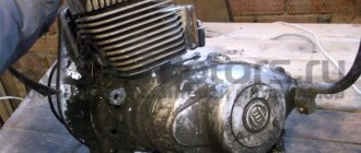
Like most Soviet equipment, this cargo scooter is reliable and easy to use, but a little rough around the edges.
Wiring diagram of Ant moto equipment
Instructions for installing a magneto on an Ant scooter with your own hands, video
Hai! This wiring diagram of the Ant equipment will be useful to those who restore old Soviet scooters. On our website All about motorcycles, such biker mechanics will find many useful images, as well as texts with tips on tuning iron horses, etc.
This resource also provides news from the world of biker sporting events.
The famous domestic scooter has become a rarity these days. Only occasionally is he encountered on the endless roads of his great homeland. You can buy it for relatively little money. On this motorcycle site you can study the technical characteristics of this utility vehicle.
Explanations for the Ant Moto wiring diagram:
1) Direction indicators with bulbs.2) Battery (battery).3) Scooter speedometer.4) Speedometer dial backlight bulb.5) Motorcycle ignition system spark plug.6) Ignition system coil.7) Ignition system capacitor.8) Switching mechanism/ turning off the high beam and the sound signal. 9) Front parking light bulb. 10) Main lighting bulb (low/high beam). 11) Turn signal switch. 12) Sound signal playback device. 13) Scooter turn signal relay. 14) Switch. 15) Night light switch. 16) Generator operation identification indicator light. 17) Neutral transmission identification indicator indicator. 18) Identification mechanism for engaging neutral gear in the gearbox.19) Motorcycle clutch.20) Bike dynastarter.21) Interrupter for the ignition system of a Soviet scooter.22) Ignition system lock.23) Ignition system fuse.24) Stop switch/switch signal.25) Moto Ant relay-regulator.26) Switch block.27) Brake light bulb.28) Rear marker light.
How to connect a dynastarter to a relay regulator?
Connecting the dynastarter to the relay regulator is not easy, but very simple. Didn't you know? And what exactly is there to connect? Some measly four wires. To some ancient relay. Well, okay, today I won’t rant too much, it’s better to get straight to the point.
Four wires come out of the dynastarter stator, which are directly connected to the relay-regulator in a certain order: the first (clockwise, if the dynastarter stator is placed with the brushes down) wire (thin) goes to the “YaSh” terminal, the second wire (thin) goes to the terminal “Ш”, the third wire (thick) goes through the fuse to the “YaSh” terminal, the fourth wire (the thickest) goes to the “C” terminal.
Dynastarter wiring harness suitable for relay regulator. A thin wire with a plug at the end is connected to the “Sh” terminal, a thin wire with a regular terminal at the end is connected to the “YaSh” terminal, a thick wire with a fuse is also connected to the “YaSh” terminal, the thickest wire is connected to the “C” terminal of the relay regulator
And here we have a relay-regulator in person to which all this junk is connected.
Electrical circuit diagram of the Ant scooter
Scooter ant
Hai! This wiring diagram of the Ant equipment will be useful to those who restore old Soviet scooters. On our website All about motorcycles, such biker mechanics will find many useful images, as well as texts with tips on tuning iron horses, etc.
This resource also provides news from the world of biker sporting events.
The famous domestic scooter has become a rarity these days. Only occasionally is he encountered on the endless roads of his great homeland. You can buy it for relatively little money. On this motorcycle site you can study the technical characteristics of this utility vehicle.
Explanations for the Ant Moto wiring diagram:
1) Direction indicators with bulbs.2) Battery (battery).3) Scooter speedometer.4) Speedometer dial backlight bulb.5) Motorcycle ignition system spark plug.6) Ignition system coil.7) Ignition system capacitor.8) Switching mechanism/ turning off the high beam and the sound signal. 9) Front parking light bulb. 10) Main lighting bulb (low/high beam). 11) Turn signal switch.
12) Sound signal playback device.
13) Scooter turn signal relay. 14) Switch. 15) Night light switch. 16) Generator operation identification indicator light. 17) Neutral transmission identification indicator indicator. 18) Identification mechanism for engaging neutral gear in the gearbox.19) Motorcycle clutch.20) Bike dynastarter.21) Interrupter for the ignition system of a Soviet scooter.22) Ignition system lock.23) Ignition system fuse.24) Stop switch/switch signal.25) Moto Ant relay-regulator.26) Switch block.27) Brake light bulb.
28) Rear marker lamp.
Part 3. Behind the wheel and Moto - separate components of scooters.
October 1957 - A little information on the dyno starter - a device that acts as a generator and starter on a motor scooter.
(Behind the wheel, 1 page). December 1957 - Description of the chassis of the Tula T-200 passenger scooter. (Behind the wheel, 1 page).
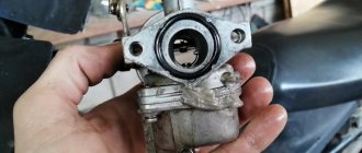
December 1961 - About the K-36 carburetor, which was used on Tourist and TGA-200 (Ant) scooters. (Behind the wheel, 2 pages).
August 1965 - About why the automatic ignition advance was removed. (Behind the wheel, 1 page).
July 1974 - A short article about shock absorbers and their design. In addition, you can find interesting operating diagrams of the shock absorber and general data on the models. (Behind the wheel, 3 pages).
Inverted version of the table.
January 1976 - Detailed information on Soviet tires. There is little to do with scooters, but the types of tires that were used on them are in the table. (Behind the wheel, 3 pages).
March 1976 - General information on spark plugs and some types of their malfunctions. There is a specific connection with scooters only when listing the models of spark plugs and the cars on which they were used. (Behind the wheel, 4 pages).
September 1977 - About the new K-62 carburetor, which replaced the K-36 model and began to be installed on Tulitsa scooters and almost all subsequent scooters and motorcycles of the Tula Machine-Building Plant. (Behind the wheel, 2 pages).
January 1979 - About batteries that were installed on scooters. (Behind the wheel, 1 page).
February 1991 - Carburetor K-65 which replaced the K-62. (Moto, 2 pages).
February 1991 - Some more information about tires. (Moto, 2 pages).
February 1992 - Construction of the front fork, which began to be installed on the Tula 5.951 off-road motorcycle. (Moto, 3 pages).
March 1992 — More about the battery. (Moto, 1 page).
April 1993 - Tula motorcycle gas tank 5.951. (Moto, 2 pages).
July 1993 - Information about old carburetors, of those listed on scooters K-28 and K-36 were installed. (Moto, 2 pages).
April 1994 - Construction of the Ant gearbox and drive suspension, i.e. rear axle as a whole. (Moto, 4 pages).
October 1994 - Information on lamps, in the table at the end there are types of lamps installed on Tula scooters. (Moto, 4 pages).
Same bonus - all articles in one file: part 3.pdf
Assembly
I bought this main bearing. It seems to be our production. There are Chinese analogues in stores - they are more expensive, but I don’t know what their quality is... I try to buy something that may not be of such super-duper quality, but at least one that has been proven over the years.
The quality of production is such that there is essentially nothing to complain about. The price is quite reasonable - 350 rubles.
We press the inner race of the main bearing onto the right crankshaft journal. External - screw the stator flange of the dynostarter and press it into the crankcase until it rests against the flange.
We install the oil seal, retaining ring and main bearing into the left half of the crankcase. I'm installing a new main bearing. It is closed, but it doesn’t matter: we open it, wash out the factory grease and install it in the crankcase.
Lubricate all bearings and working edges of oil seals with clean engine oil. And very carefully, so as not to accidentally wrap the edge of the oil seal - insert the crankshaft into the left half of the crankcase, and knock out the crankcase guides by 5-6mm.
We degrease the crankcase connector, install a new gasket and install the second half of the crankcase.
Tighten the bolts and immediately so that nothing gets into the crankcase -. I'm installing a new piston, cylinder head and reed valve body. The piston one, like everything else, is of no particular origin - most likely Rostov, but clearly not Chinese. I didn’t want to get involved with this counterfeit, but the owner didn’t want to wait until they bore the cylinder and put a liner in the cylinder head and insisted on buying it. You see the prices for spare parts - it’s up to you to decide whether to contact this new product or not.
We install the second main bearing into the crankcase and secure it with a retaining ring.
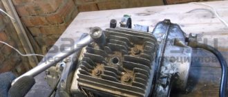
It's no secret that the engineers of the Tula plant have created equipment with which the average owner has to feel like a mechanic. To this day, having found another problem, Ant’s owner has to pick up a tool, remembering the would-be engineers. One of the main problems is the engine of the Ant scooter, which is repaired in most cases of breakdowns.
Things went wrong
How to set the ignition on a VAZ 2106 yourself
Of course, the engine had to be half charged with spare parts made by no one. I suspect that the counterfeit goods with which I had to tinker for the last two days are being produced in some garage in Rostov-on-Don, or that the local workers are secretly making this nonsense at the factory. In any case, according to my information, traders bring this disgusting stuff from Rostov. The engine to which I have devoted the last two days has already been converted to a magneto. I don’t know why he bought it - I didn’t ask him for it. The old one was in good condition. Well, since I bought it, we’ll install it. It’s none of my business, of course, but I have an extremely negative attitude towards this kind of collective farm tuning.
Photo report: Repair of the dynostarter of the Ant scooter, Tula
VIDEO ON THE TOPIC: Contactless ignition of BSZ Ant, TMZ. My version But okay, today we’re not going to talk about that…. In such cases, I first inspect the wires going to the dynastarter and the relay-regulator, check the operation of the relay-regulator and, for complete happiness, forcefully apply current to the shunt winding; if after all that has been done, charging does not appear, then the fault is hidden in the dynastarter itself. After removing the casing, we need to unscrew the breaker cam behind which there is a nut securing the rotor. Now you need to unscrew the nut on the trunnion. The dynastarter rotor can only be removed using a special puller; all your attempts to remove the rotor using hammers and chisels are doomed to failure, so I don’t recommend it... Then we screw the puller all the way into the rotor and begin tightening the screw.
Forgot your password? Changed p.
Checking the brushes
We turn the stator over with the brushes facing us, check the brushes for wear: the working surface of the brushes is slightly thinner than the main one, if the working surface on your brushes is worn out, replace such a brush with a new one.
Worn brush
Normal brush
After checking the brushes for wear, we check one by one how the brushes move in the sockets; if the brushes hang up, we sharpen them with a file until they move in the sockets without jamming.
After all that has been done, we install the dyno starter parts in place, adjust the ignition and enjoy the impeccable operation of the electrics of your scooter.
Improving the carrying capacity, or making a dump truck out of Ant
The Ant scooter is a powerful device, but most owners are not averse to increasing the model’s load-carrying capacity. In addition, you can remake the body and make it folding (like a dump truck).
However, there are some nuances and the main thing is not to overdo it. As you know, the load capacity is about 250 kg; in practice, large loads can also be accommodated. But it should be remembered that with such a load the speed will be much slower (up to 35 km/h).
You can increase the load capacity by increasing the sides. However, the scooter frame will need to be strengthened.
Welding can be considered the most optimal option, but you can do it without it (the additional frame is made from wood).
In this situation, the body is moved forward or left in its place, but it is prohibited to move it back.
It is possible to consider the option of installing separate booths on such scooters, which will require separate costs.
The following mechanisms are most often used for a dump truck:
- cable winches;
- hydraulics with automatic drive;
- methods using door hinges, etc. (so-called “manual”).
As for hydraulics, you will also need to use a pump. The total costs with this approach may exceed the cost of the scooter itself.
Let's consider options for implementing the idea:
1. Using automation.
The body is attached to an additional frame, which is connected to the main frame using hinges. Lifting can be carried out using a diamond jack, which operates with a simple electric drive. The electric drive itself can easily be made using the window lifters of a simple car. This is the essence of automation, when the body tips over with the press of one button.
The only disadvantage of such a conversion is the final cost of the work. The price depends on the spare parts used.
2. Manual method.
The body, as in the automatic method, is mounted on an additional frame. The frame is also attached to the main one.
The convenience of this method is that, if necessary, it is possible to simply remove the body (for example, when you need to transport long pipes, etc.). Such long objects can be attached directly to the frame.
Subtleties of production
In practice, it is recommended to additionally install chains that will protect the loops from being pulled out. Ordinary door handles from household appliances or car mechanisms can serve as closures.
When constructing a removable body, you will also need to attach the tank, license plate, and turn signals directly to the frame (not to be confused with the body). It is necessary to ensure that the center of gravity is near the axes of the loops (about 30 cm in relation to the rear edge). This is the only way the body can be tipped over manually without any problems.
So, the Ant scooter today is not only a means of transportation, but also a powerful mini-dump truck at home. Despite the fact that the vehicle has not been sold on the auto market for a long time, it is still worth purchasing it second-hand. Thus, from a simple moped, thanks to little effort, we acquire a powerful dump truck and a sophisticated vehicle.
Disassembly
We remove everything that interferes with the removal of the rotor, hold the rotor by the fan with your hand and unscrew the nut
A good owner should have a washer and a lock under the nut. The bad one won’t even have a nut...
Remove the rotor from the crankshaft. The rotor can be removed either with a factory puller or with a homemade one - it makes no difference.
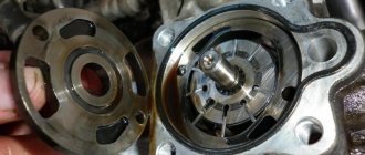
First of all, we inspect the rotor commutator and brushes. The commutator must not show any wear or damage. For example, this collector is just dirty and after we wash it, the dynostarter will start working again.
And some deer broke out the lamellas of this collector. Such a rotor will be difficult to help and easier to throw away. To prevent this from happening to your rotor, select bolts for the coupling for the magnet and the fan of the appropriate length, and do not put everything you have on hand there...
This collector was pulled up by something, the lamellas were shorted together and the dynostarter died. If you find a good turner, he will be able to sharpen the scuffs and the rotor’s performance will be restored.
There are situations when the rotor is dropped or the windings are hit. You understand that damage to the power windings will not improve the reliability of your scooter’s power supply system, so handle such devices very carefully and use pullers, and do not knock them down like tractor drivers with a hammer.
On this rotor, someone smacked the windings with relish.
Search data for your request:
Paramoto-Forums Paramoto-Forum Question: what is bad about the ant's movement? Stoker Topic Author. Question: what is bad about ant movement? Compression ratio 9.
Search data for your request:
Schemes, reference books, datasheets: Discussions, articles, manuals:
Wait for the search to complete in all databases. Upon completion, a link will appear to access the found materials.
WATCH THE VIDEO ON THE TOPIC: → Charging diagram for TMZ motorcycles.
→WIRING DIAGRAM TMZ ➧DISASSEMBLY, PRINCIPLES OF OPERATION
You need to remove and put away the batteries, the fact is that after installing the magneto, the ant will actually no longer need them! In the center of the lid is the manufacturer's logo. Carefully cut a through hole along this emblem, you will get a hole with a fairly large diameter. But when cutting, you need to leave at least 5 - 7 millimeters of body metal for attaching the magneto. Of course, it is better to cut a hole on a lathe, but if you don’t have one, you will have to work with a drill, over and over again, drilling holes around the intended hole with a thin drill.
When it breaks, then all this uneven disgrace is processed with a round file. You need to cut a donut out of metal, the outer diameter of which will be slightly larger than the distance between the magneto mounting brackets, and the inner diameter of the donut will be equal to the diameter of the hole made in the engine casing that was drilled!
We make a connection with the crankshaft. You need to try to fix the magneto drive to the fan; this needs to be done between its two halves, placing a strip of rubber. Rubber will remove vibration and noise. If something is not clear, here is a photo of remaking the ant and installing a magneto on it!
At the beginning, I would like to advise you to think about everything again, a magneto is not the best option for the Ant, the standard ignition system is no worse, and the magneto is not designed for long-term operation.
We cut out a hole of large diameter, carefully process the edges of the hole using a file. Next, we fix the spacer coupling, made independently, with four bolts on the rotor, mounting directly on top of the fan.
To install a magneto, you must first purchase or make your own adapters and an attachment for the rotors. How to install a magneto on an Ant scooter?
The procedure is as follows: Unscrew the engine protection cover. All actions take place on the right side of the engine. We unscrew and remove the air duct along with the cover; it covers the fan. It is this cover that needs to be altered a little; it is on it that we will install the magneto.
Schematic diagram
As for the Ant's ignition system, you can upgrade it yourself. You can reduce the current passing through the contacts of the breaker using a transistor switch TK-102 (Fig. 1), which was used on the most common trucks in the past, ZIL-130, GAZ-53A, etc.
By reducing the current in this way by 6-8 times (to 0.3...0.8 A), we will make the breaker contacts almost eternal. The disadvantages of this solution include increased requirements for the cleanliness of contacts, since oil, dirt and dust caught between the contacts no longer burn out, as was the case with a conventional ignition system.
Rice. 1. Connection diagram of the transistor switch TK-102.
The use of a transistor switch makes it possible to use a higher-voltage B-114 ignition coil, which has a large secondary winding (41,500 turns). Since the voltage on the spark plug will increase from 17 to 25.30 kV, you can use a spark plug with a gap of up to 1.2 mm, which will save about 30% on gasoline.
System assembly and installation
The contacts in the breaker, the capacitor, the ignition bobbins and the armor wires, which are part of the previous ignition device, are probably eliminated. The switch should be installed in the glove compartment on the right, and the ignition coil directly under the tank. There are no gaps for fastening on the reel, which means it can be attached using a thick layer of adhesive tape. The standard bolt is also eliminated along with other parts.
In place of the bolt, install a pin of the specified size and put on a washer. Then, the rotor is tightened with a nut located at its end. The hall sensor is attached to the stator by any means. The basic rule when installing it is to set the optimal cross-sectional distance of the modulator and the ratio of the radius and line of symmetry.
When the hall sensor can be secured, we apply the modulator. It should fit into the hole made in the sensor. In most situations, there is a discrepancy between the sizes, so it is necessary to place washers on the stud. If you manage to maintain the required gap, it is recommended to install an engraver and tighten the modulator with a third-party nut.
Electrical circuit of the motor scooter Ant TG 200
The Ant TG 200 is based on its passenger car predecessor, the Tula T-200. The wiring diagram does not have complex components and is suitable for analogues of the Ant TG 200 scooter: TG-200F, TG-200I, TGA 200, TGA 200-01.
Download the electrical diagram of the Ant TG 200 scooter:
- Direction indicators
- Scooter battery
- Speedometer
- Speedometer backlight
- Spark plug
- Ignition coil
- Capacitor
- High beam and horn buttons
- Front side lights
- Low and high beam headlight
- Turn signal switch
- Sound signal
- Turn signal relay
- Switch
- Side light switch
- Battery charging indicator
- Neutral indicator
- Neutral sensor
- Clutch
- Scooter engine starter
- Breaker
- Egnition lock
- Fuse
- Brake light switch
- Relay regulator
- Switch block
- Brake light
- Tail light
Connection
- To terminal “B” we connect a thick red wire coming from the battery and a red thin wire with a fuse coming from the ignition switch (terminal AM)
- To the “P” terminal we connect a thin orange wire coming from the ignition switch (CT terminal)
- To terminal “C” we connect the thick red wire coming from the dyno starter.
To terminal “W” we connect the thin black one coming from the dyno starter
To the “YaSH” terminal we connect a thick black wire with a fuse coming from the dyno starter, a thin black wire coming from the dyno starter and a blue wire going to the generator charge control lamp
Source
Ant dino starter operating principle
The dynostarter as a device is as far from complete perfection as our VAZ plant is from the premium segment. But if at least once a season you carry out competent maintenance of the collector unit, switching equipment, and battery, then with all its inherent shortcomings, the dyno starter can last a very, very long time, up to 30,000 km, or even more.
Basic faults
- Mechanical, caused by natural wear, combustion of windings, destruction of contact groups
- Structural, due to design features
- Malfunctions of the relay regulator that lead to dyno starter failure
The most unpleasant malfunctions are related to mechanics: combustion of windings, interturn short circuit, wear or destruction of the commutator. Other mechanical faults such as wear or sticking of brushes, contamination of the commutator, breakage or oxidation of wires and terminals can be eliminated quite easily.
Diagnostics
The first sign that something has burned out, shorted or broken in the dyno starter or relay regulator is when, out of the blue, right in the middle of the road, your battery charge control lamp comes on.
If this happens to you, then the first thing you need to do is inspect the wires going from the dyno starter to the relay regulator, check the fuse, remove the cover from the relay regulator and at least visually determine the integrity of its elements, remove the rotor and see what’s wrong with the brushes and collector and if nothing suspicious is found there, turn to a very competent electrician for help.
You can try to identify the fault yourself, and within the framework of this article it would be possible to describe all the stages of testing, including the author’s developments, but none of you will do this. In the best case, poke it a couple of times with the tester and you’ll give up on this matter, or even end up using a magnet instead of a dynostarter.
The second sure sign that your dyno starter is in perfect order, but it’s just time to service it, is when, at idle and low engine speeds, the charge warning lamp first begins to blink slightly, then begins to burn more steadily and after a while begins to burn at full intensity throughout engine speed range.
In both the first and second cases, without disassembling the dynostarter, little can be learned about its condition, so if there are any complaints about its operation, we roll up our sleeves, prepare the tool and get started.
Disassembly
We remove everything that interferes with the removal of the rotor, hold the rotor by the fan with your hand and unscrew the nut
A good owner should have a washer and a lock under the nut. The bad one won’t even have a nut...
Remove the rotor from the crankshaft. The rotor can be removed either with a factory puller or with a homemade one - it makes no difference.
First of all, we inspect the rotor commutator and brushes. The commutator must not show any wear or damage. For example, this collector is just dirty and after we wash it, the dynostarter will start working again.
And some deer broke out the lamellas of this collector. Such a rotor will be difficult to help and easier to throw away. To prevent this from happening to your rotor, select bolts for the coupling for the magnet and the fan of the appropriate length, and do not put everything you have on hand there...
This collector was pulled up by something, the lamellas were shorted together and the dynostarter died. If you find a good turner, he will be able to sharpen the scuffs and the rotor’s performance will be restored.
There are situations when the rotor is dropped or the windings are hit. You understand that damage to the power windings will not improve the reliability of your scooter’s power supply system, so handle such devices very carefully and use pullers, and do not knock them down like tractor drivers with a hammer.
On this rotor, someone smacked the windings with relish.
Cleaning the collector
Take a small screwdriver and clean out the dirt between the slats. The collector must be cleaned very carefully so as not to scratch the lamellas.
After cleaning, blow the collector with compressed air, wash it with clean gasoline and wipe it dry with a rag.
When the gasoline has completely evaporated, take a piece of some lint-free cloth, moisten it a little in gasoline and carefully rub the collector with the maximum possible force until it is perfectly clean.
Checking the rotor windings
We switch the tester to the continuity mode and check the winding contours for breakdown: we place one probe on the rotor body, and with the second we touch all the lamellas in turn. If the tester beeps on any lamella or displays a lot of numbers on the screen, the winding is broken and the rotor should be replaced.
Checking the stator windings
We unscrew the stator mounting bolts, tap it around with a wooden mallet, remove it from the engine, turn it over with the wires towards you, switch the tester to the continuity mode, connect the tester probes to the two rightmost terminals of the windings, if the tester beeps, there is no winding breakage.
We do the same with the remaining two wires: put the tester into dialing mode, connect the tester probes to the ends of the wires, if the tester beeps, there is no winding break.
After checking the windings for breaks, we carry out an additional check of the stator for breakdown of the windings: we switch the tester to the continuity mode, alternately touch the wires with one probe, and touch the stator housing with the second. If the tester does not beep, the windings are not broken. If it beeps or numbers appear on the screen, the windings are broken to ground.
Homemade ATV from the Urals
Heavy Ural motorcycles are not very popular. One of the reasons is the huge consumption of gasoline. Many motorcyclists and bikers are not satisfied with the large dimensions of the Urals. Despite this, folk craftsmen are interested in such motorcycles. Points such as the presence of reverse gear and a fairly powerful four-stroke engine are very tempting in terms of converting an old Ural into an ATV. Its cost is ultimately much lower than its European counterpart, and the engine power is much higher. Such homemade products from the Ural motorcycle will appeal to everyone who likes to create with their own hands.
Design Features
Craftsmen from the city of Barnaul received a successful version of a homemade ATV:
- The Ural motorcycle was taken as a basis; in particular, the frame with the engine was left.
- The reinforced gearbox was removed from the motorcycle of another model of the domestic motorcycle - “Dnepr”.
- The drive had to be made of a cardan type, due to the fact that options with sprockets and chains are less reliable.
- Two pairs of wheels fit well from the Gazelle car. The appearance of the ATV turned out to be rough and uncouth.
The engine power of a homemade ATV allows you to pull a load weighing up to 500 kg. Without a load on an asphalt road, the wheels slip during the start.
The management of Russian automobile factories should think about the issue of producing domestic ATVs and tricycles, taking advantage of the excellent experience, for example, of Barnaul craftsmen. Moreover, most of the components had already rolled off the assembly lines of these enterprises at one time!
Homemade Ural motorcycles can look different. In any case, this technique is impressive.
Electrical circuit of the motor scooter Ant TG 200
For the most part, the circuit may be needed due to a malfunction of the basic elements of movement.
How to set the ignition on an Ant scooter in 5 simple steps? Insert a rod through the hole from which the spark plug was removed and press it against the piston head. The final reason for using the diagram below is to check the flywheel, which receives torque when the piston moves. How to set the ignition on an Ant scooter in 5 simple steps? Thirdly, the scooter's headlights are supplied with the current needed at night, and the brake lights and turns are also supplied with electricity. The disadvantages of this solution include increased requirements for the cleanliness of contacts, since oil, dirt and dust caught between the contacts no longer burn out, as was the case with a conventional ignition system.
All you need is very thin paper, a narrow rod and a set of keys. When the paper is released when the piston is lowered to the depth of the mark made, the ignition will be set correctly. Since the spark plug voltage will increase from 17 to
But it has the most necessary things, and the connection diagram will help you figure out the breakdown or configure the wiring. When the paper is released when the piston is lowered to the depth of the mark made, the ignition will be set correctly. Supplying current to lighting devices and signal signs, turn signals, parking lights, brake lights. Electrical circuit of an Ant scooter, electrical equipment. Electrical circuit of an Ant scooter. Electrical equipment. Electrical equipment of an Ant scooter is used mainly in three areas.
Recent Entries
The electrical equipment of the Ant scooter is securely mounted on the body of the scooter and has good insulation, so the likelihood of a short circuit is negligible. Due to this action, the piston moves, transmitting torque to the flywheel. Insert a rod through the hole from which the spark plug was removed and press it against the piston head. For the most part, the Ant motorcycle is designed to transport large loads, so it was not equipped with special lighting parts. But the Ant motorcycle is quite simple in design, so its electrical circuit is very simple. However, to find the problem, you need to keep a tester at hand. For the most part, the Ant motorcycle is designed to transport large loads, so it was not equipped with special lighting parts. Of course, for this you need to have a special tester, thanks to which you can always determine the malfunction of a particular mounting unit or part.
The Ant generator and starter are combined in one electric machine. All equipment has excellent insulation, eliminating the possibility of short circuits and harm to the driver. Place paper between them and pinch. For the most part, the circuit may be needed due to a malfunction of the basic elements of movement. Modernization of the SOVIET ANT
Typical faults
Among the typical malfunctions of this unit, the following are worth noting:
- Return spring failure
A broken return spring causes the winding lever to no longer return to its place after starting the engine.
- Broken or worn ratchet teeth. Breakage or wear of the flywheel teeth causes the winding lever to slip
- Worn thrust bolt. Wear of the thrust bolt leads to the fact that after starting the engine, the carriage hitting it does not slide, but continues to be engaged
- Another common malfunction is shaft breakage. Unfortunately, I don’t have photos of the torn shaft at the moment.