Just a couple of months ago, an old client asked to overhaul the engine of his Ant for the season. He is not greedy for money - he promised to buy everything needed for repairs. We agreed, the client pulled the engine off the frame and brought it for repairs. After disassembly, an unpleasant picture emerged: the piston, crankshaft, motor chain and almost all bearings were worn out.
The customer insisted on purchasing a new crankshaft. They are now in abundance in any store - I don’t want to take them, but their quality is still good... I resisted for a long time and in the end the client found a used engine from which I pulled the crankshaft. Of course, it was slightly worn out, but the bearing of the lower head of the connecting rod was intact and intact, and we didn’t need anything more.
Preparation
Before installing the crankshaft, it is advisable to check it for runout. And it doesn’t matter whether the crankshaft is new or used, you need to check it otherwise, with today’s “quality” of spare parts, you can repair the engine and then suffer with it for a long time and tediously. We place the crankshaft on the prisms and check the runout, the norm is no more than 0.03 mm. If you don't have an indicator, take the crankshaft to a good turner
Build errors
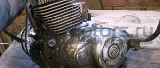
In most cases, the right main bearing of the crankshaft fails due to an assembly error almost in the first season after repair. The engine that we are now repairing is no exception. The bearing has practically crumbled and in any case needs to be replaced with a new one.
The mistake is that when installing the flange on which the dynostarter stator is attached, the oil channel through which lubricant flows to the main bearing and oil seal is sealed.
To ensure that the main bearing lasts at least several seasons, cut the gasket under the flange a little along the contour of the oil channel and when you put the flange in place, do not smear anything with sealant there.
And one more thing: to avoid self-unscrewing of the bolts securing the dynostarter stator flange to the crankcase, and they come loose very often, apply a little thread locker to the threads. If possible, use a medium-strength fixative - “blue”.
Photo report: Repair and assembly of the Ant scooter gearbox
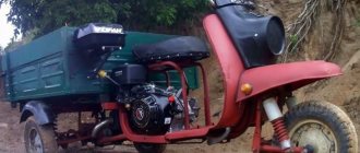
I decided to build myself a walk-behind tractor for my household. I already had an engine ideally suited for this task - from an SZD motorized stroller. But I didn’t have a suitable gearbox through which I could increase the overall gear ratio of the transmission and at the same time realize the ability to move in reverse.
So I thought this way and that, and in the end I decided to “dance” from some mass-produced gearbox or, at worst, to adapt a box from a Ural for this purpose. I didn’t have to look for the device I needed for a long time: on occasion, I was given two killed “Maravievsky” gearboxes. One of them “caught a wedge” about twenty years ago and was left in the barn awaiting its finest hour, and the second still showed signs of life, but had serious damage to the body and severe wear of gear teeth and bearings.
After disassembling both copies, it turned out that the support bearing of the input shaft had crumbled in the jammed gearbox. It would be fine, you might say, it’s a common thing, but the whole problem was that during operation, the balls of the scattered bearing got between the gear teeth, which led to their breakage. Everything else, including the housing and internal parts of the differential, to my great joy, remained intact and unharmed. The internal parts of the second gearbox turned out to be in much better condition, but still, years of merciless use left their negative mark on their condition.
At first I wanted to buy the damaged parts from the store. Oddly enough, the spare parts I needed were found in the store - I don’t want to take them. And most importantly, the spare parts were still Soviet-made, coated with a thick layer of grease and wrapped in special paper - not 100% China. But the price for them made me think... In general, for two gears and an intermediate shaft, the trader asked me more than two rubles + new bearings, a piece of paronite for a gasket and a set of seals, and absolutely - the price appeared to be three rubles...
I thought about it and decided to limit myself to buying new bearings and seals, and borrow the damaged gears and intermediate shaft from another gearbox. In general, make the gearbox a classic “brute force”, which is exactly what will be discussed in this article.
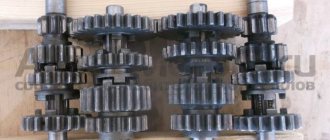
So, all the parts have been cleaned, washed, checked for acceptable wear and damage, the threads have been run, all that remains is to collect all this junk “to the heap”.
We install the bearings in the gearbox housing preheated with a technical hair dryer. If anyone needs it, here are the bearing numbers:
- 18 GPZ_204_KZ - 2 pcs (input shaft);
- 4_GPZ_60203_K-2pcs (intermediate shaft);
- 4_GPZ_7_207_K_5-2pcs (differential housing);
We lay the right half of the body on planks so that the shafts coming out of the body hang freely in the air and do not interfere with work. We place a standard thrust washer on the support bearing of the input shaft.
We put the gear on the input shaft as shown in the picture and insert it into the housing. Before installing the gears, pay attention to their teeth and jaw couplings that engage the gears with each other. The teeth should not be chipped, damaged, cracked or show signs of excessive wear. The cams must be of the correct shape with sharp, not licked edges.
We put the intermediate shaft in place.
Thoroughly clean and wipe the working surface of the differential axle shaft and the cup into which the axle shaft fits. We put a standard thrust washer on the axle shaft and insert it into the cup. We take a set of measuring probes, select the thinnest one from them and try to insert it between the working surfaces of the differential cup and its axle. If the selected probe passes between the parts without noticeable force, take a thicker probe and repeat the procedure again until the probe enters with noticeable force.
My measuring process was completed on a probe 0.05 mm thick; a thicker probe no longer passed between the parts, which means that the production in this connection does not exceed 0.05 mm. The norm is no more than 0.1 mm. If your measurement procedure ends at 0, 1 mm or more on the probe, replace the axle shaft or cup with a new one.
In the same way, we put the satellites on the axle one by one, while carefully making sure that they stand exactly in the place where they stood before disassembly, that is, in the place where the output will be maximum. And we try to insert a measuring probe between the axle and the inner hole of the satellite. The permissible wear limit, as in the first case, should not exceed 0.1 mm.
We insert the satellite axis into the cup so that it extends slightly beyond the edge and put a thrust washer on it.
We put the satellite on the axle, push the axle further, put on the second satellite, adjust the thrust washer under it and push the axle.
We rotate the axle so that the hole for fixing it coincides with the hole in the cup and secure it from falling out with a locking pin.
We connect the cups to each other, put thrust washers on the outer ends of the axle shafts and secure them with retaining rings. The axle shaft can be fixed immediately after installation in the cup, or it can be fixed later - it doesn’t matter.
We put the gears on the differential housing. There is no particular difference where to put which gear. It will work either way or that way. We put locking plates on the bolts and carefully tighten the body with them. Try to tighten the bolts evenly, crosswise and as tightly as possible; several gearboxes have passed through my hands whose bolts were loosened, which is why both the bolts themselves and the housing were broken during operation.
After the final tightening of the bolts, we bend the locking plates.
We install the differential housing in its place.
We put the reverse gear on the fork of the reverse mechanism, insert the pin on the fork into the groove on the reverse lever and insert the fork rod into the mounting hole of the housing.
We knock out the housing guides so that they extend 5-6mm onto the housing connector surface, degrease the connector surfaces, apply sealant to the mating surfaces, lay a gasket and connect the housing halves.
We tighten the housing with bolts, install the axle shaft covers and bearing plugs.
Assembly
I bought this main bearing. It seems to be our production. There are Chinese analogues in stores - they are more expensive, but I don’t know what their quality is... I try to buy something that may not be of such super-duper quality, but at least one that has been proven over the years.
The quality of production is such that there is essentially nothing to complain about. The price is quite reasonable - 350 rubles.
We press the inner race of the main bearing onto the right crankshaft journal. External - screw the stator flange of the dynostarter and press it into the crankcase until it rests against the flange.
We install the oil seal, retaining ring and main bearing into the left half of the crankcase. I'm installing a new main bearing. It is closed, but it doesn’t matter: we open it, wash out the factory grease and install it in the crankcase.
Lubricate all bearings and working edges of oil seals with clean engine oil. And very carefully, so as not to accidentally wrap the edge of the oil seal - insert the crankshaft into the left half of the crankcase, assemble the gearbox and knock out the crankcase guides by 5-6mm.
We degrease the crankcase connector, install a new gasket and install the second half of the crankcase.
We tighten the bolts and immediately, so that nothing gets into the crankcase, install the piston. I'm installing a new piston, cylinder head and reed valve body. The piston one, like everything else, is of no particular origin - most likely Rostov, but clearly not Chinese. I didn’t want to get involved with this counterfeit, but the owner didn’t want to wait until they bore the cylinder and put a liner in the cylinder head and insisted on buying it. You see the prices for spare parts - it’s up to you to decide whether to contact this new product or not.
We install the second main bearing into the crankcase and secure it with a retaining ring.
We adjust and assemble the clutch mechanism.
We install the manual start mechanism and close the whole thing with a standard lid.
Photo report: Motor scooter engine repair “Ant”
In the article: Disassembling the engine of the Ant scooter, the process of completely disassembling the TMZ engine was shown in detail, after which all parts were carefully inspected and checked for acceptable wear and damage.
All the oil seals and bearings of the engine did not pass the test for suitability for further operation, the cylinder - it had to be bored to a repair size, the motor chain, and the first gear gear - due to wear on the bushing, and some other small things. Not so much if you take into account the age and “quality” of service of our “ant”...
We managed to buy all the worn-out parts without any problems, so all that was left was to collect all this “Soviet junk” to the heap. What exactly are we going to do today?
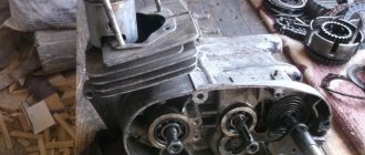
Before assembly, all planes and parts of the engine are thoroughly washed and cleaned of dirt, oil and remnants of old gaskets and sealant. We pay special attention to the condition of the crankcase and threaded connections, the main work on repairing the crankcase is described in detail in the article: Repairing the crankcase of a scooter engine, we prepare ourselves a clean workplace, and proceed to a very interesting and exciting activity...
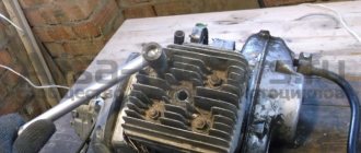
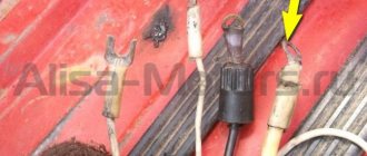
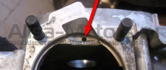
We lay the right half of the engine on the blocks, clean and blow out the oil channel (marked with an arrow), degrease the plane of the dynastarter mounting flange, lay a new gasket and be sure to cut it a little along the contour of the oil channel in the place where it is marked with an arrow.
It is not advisable to apply sealant to this connector, since there is a danger that the sealant will get into the oil channel and cut off the oil supply to the oil seal and the crankshaft main bearing. What this leads to is written in the article: Repair of the dynastarter of the Ant scooter
We install a new oil seal in the dynastarter stator mounting flange, degrease the surface, apply “blue” thread locker to the fastening bolts and finally tighten the bolts. The bolts must be tightened very well, as they are constantly unscrewed, which leads to serious engine damage.
We turn the half over, heat the seat of the main bearing with a heat gun and, using a mandrel, install the new main bearing (in our case) into the crankcase.
We take the other half of the crankcase, be sure to clean and blow out the oil channel (marked with an arrow), insert a retaining ring into the seat of the main bearing and, in the same way, install the second main bearing in its place.
We are looking for a sheet of metal of suitable thickness (7-8 mm), insert our sheet between the cheeks of the crankshaft and in this position, using a mandrel, press the inner race of the main bearing onto the axle.
The crankshaft of this engine was carefully checked for faults and correct geometry; the main work on diagnosing the crankshaft is described in detail in the article: Methodology for determining faults in the crankshaft of a scooter or motorcycle
Also, on this crankshaft it was necessary to replace the bushing of the upper head of the connecting rod; this work is described in more detail in the article: Replacing the connecting rod bushing of the motorcycle “Izh-Planet”, “Jupiter”, “Ant”
We insert the crankshaft into the left half of the crankcase, we carry out the final installation of the crankshaft into the crankcase using a simple device; details of the correct installation of the crankshaft into the crankcase can be found in the article: Repairing the Voskhod-ZM motorcycle engine, not with a sledgehammer!!! As they often like to do on “collective farms”...
After the final installation of the crankshaft into the crankcase, we assemble the gearbox in the correct order, how to assemble the gearbox is written in the article: Repair and assembly of the gearbox (box) of the Ant scooter,
We lay the crankcase half with the assembled gearbox on planks so that the shafts hang freely in the air and do not interfere with work, degrease the crankcase planes, install the guide bushings (marked with arrows) in their places so that they extend slightly above the crankcase plane (5-6 mm) , apply sealant to both halves and place a new gasket.
Lubricate the lip of the oil seal and the main bearing of the crankshaft with engine oil and place the second half of the crankcase on top.
We fill the tendril of the gearbox shaft retainer spring inside the crankcase.
Using a wooden mallet, tap the halves until they come together completely and tighten the crankcase mounting bolts.
Lubricate the main bearing and the edge of the second crankshaft oil seal with engine oil, then use a mandrel to install the oil seal in its place.
We put the locking ring in its place.
We also install the crankshaft support bearing there and secure it with the second retaining ring.
Now all that remains is to install the piston group on the engine, check and assemble the clutch parts and install the kickstarter mechanism. After which you can install the engine on the frame.
Recommendations
Several “Ants” with a torn dynostarter stator flange have already passed through my hands. To avoid this trouble, I screw the stator onto good bolts with a screwdriver: under the internal hexagon + I apply “blue” thread locker to the threads. If your engine is converted to a magneto, then simply do not install a stator; it will be more reliable.