How to set the ignition to a magneto on an ant
VIDEO ON THE TOPIC: Setting the ignition on the ant correctly!
Moreover, the engine does not work in only two cases:. The work of any internal combustion engine is to convert the reciprocating motion of the piston into the rotational motion of the shaft. This transformation occurs with the help of the crank mechanism of the crankshaft. As in the picture below:.
Parts for installing a magneto on an Ant scooter: 1 magneto adapter, 2 attachment to the dynastarter rotor, 3 attachment to the magneto rotor. Filmed on the basis of Melitopol Professional Agrarian. Ant is a universal scooter, which is used by rural and urban residents as a means of transportation, a truck and even a tractor.
How to install a magneto on an Ant scooter. For a villager, “Ant” is everything: a motorcycle, a car, a tractor, and a truck. 8 he is indispensable on the farm. And what a shame it becomes when the batteries “die”. In rural areas there has never been an abundance of them, you can’t drive them into the city (and you can’t drive a scooter anyway!), and besides, there’s no guarantee that you’ll buy them.
And without a battery, the Ant becomes weaker than its biological brother, turning into a helpless paralytic. I had to approach the problem from the other side - abandon the battery altogether. This was done by installing a magneto on the scooter from the tractor launcher of the decommissioned Belarus.
To do this, it was necessary to make an adapter, attachments for the dynastarter rotors and a magneto. They are machined from steel and then hardened. Installation is carried out in the following sequence. Having removed the coupling from the rotor, it is replaced with a magneto rotor attachment. Then, instead of the breaker, cam base and cam removed from the dynastarter, a dynastarter attachment is installed.
The latter is fixed with the same screws that secured the base of the breaker. Three holes with a diameter of 7 mm are drilled in the fan cover, necessary for attaching the magneto adapter. The adapter itself is needed to strengthen the rather fragile cover. Be sure to place plain and split washers under the fastening nuts. The cover with the adapter is fixed in place.
Having installed the piston at a distance of 2.8-3.2 mm before TDC, “put” the magneto on the adapter so that the protrusion of its nozzle fits into the slot of the dynastarter rotor. Now, turning the magneto body, you should determine the moment of opening the contacts, and then, noting the position, mark the mounting holes. M6 thread is used. All that remains is to connect the high-voltage magneto wire to the spark plug cap, and connect the wire from the terminal on the housing to the ignition switch.
In the “Off” position, this wire should be shorted to ground; in the “On” position, it should be open. Long-term operation of a scooter with a magneto is successful. No problems starting either in summer or winter, the engine runs great. The dynastarter continues to generate electricity, which is more than enough for lighting and alarm systems.
In contrast to the method of installing a magneto on a scooter, proposed by A. Platonov (“Moto”, 1992, No. 1), I think that mine is much more convenient - you only need to make three simple parts instead of five complex ones. This will require less time and expense. In addition, at any time you can quickly return to the standard dynamo battery ignition system.
Parts for installing a magneto on an Ant scooter: 1 — magneto adapter; 2 — attachment to the dynastarter rotor; 3 — attachment to the magneto rotor.
Instructions for installing a magneto on an Ant scooter with your own hands, video
The Ant is a versatile scooter that is used by rural and urban residents as a means of transportation, a truck, and even a tractor. Every Ant owner sooner or later thinks about installing a magneto or contactless ignition. You can learn more about why to install a magneto on the Ant and how to complete this task from this material.
Feasibility of alteration
Before installing and setting up a magneto on a scooter, think about it - does it make sense? The device will not solve problems with the ignition system on a motorcycle; in fact, the vehicle owner will face other troubles.
- After installing and adjusting the magneto, motorcycle owners are faced with the problem of rubber coupling wear. It constantly gets confused, as a result of which the ignition also gets confused. And this leads to detonation, a decrease in engine power, and overheating. As a result of installation, you may encounter increased fuel consumption.
- Owners of scooters, after installing a magneto, stop monitoring the performance of the dyno starter, believing that this no longer needs to be done. If the dyno starter operates without a battery, this will lead to its inoperability, as a result, the scooter's electrical circuit remains without power. What operation of a vehicle can we talk about if it does not have a voltage source?
- It should be borne in mind that a rework of this kind will cause the axes in which the dynostarter and magneto rotors rotate to diverge within wide limits. Ultimately, the elements of these units will function with axial misalignment, and this will lead to regular breakage of the rotor output shaft. The same problem can cause accelerated wear of bearing devices.
- Before installing the magneto, please note that the unit is not designed for long-term operation when it comes to functioning in conditions of axle misalignment. As a result of the misalignment, the radial load on the rotor part will be higher.
- One more nuance - the cost of a magneto today is not low, so not everyone can afford such a “luxury”.
Contactless ignition Ant, Tula (FULL set of BSZ Muravey 2.5)
How to correctly set the ignition on a VAZ 2106 with your own hands
ATTENTION: The manufacturer GUARANTEES the operation of the entire kit during initial installation. All equipment and its elements are 100% tested before shipping
It is extremely important to completely read the installation instructions, check for problems and short circuits in other electrical equipment, and use ONLY with a working battery. The warranty on consumables of the kit (switch, coil) is 14 days from the date of receipt
Although the commutator and coil have also been tested, it is impossible to guarantee a certain guaranteed period of their operation on an engine of this type, because They are designed by the factory for installation on 4T vehicle engines. If something does not work right away, then 99.9% the problem is due to incorrect installation, or damage caused by errors in the installation or operation of other equipment. During warranty service, all transportation costs for delivery of the kit to the service and back are paid by the buyer. You accept these terms and conditions upon purchase and agree to be bound by them. If you are not confident in your abilities or do not agree with the terms of the warranty, then please refrain from purchasing.
Contactless electronic ignition system Ant, Tula.
The optimal solution for high-quality engine operation is the use of so-called non-contact electronic ignition systems (BESZ).
The most important advantage of a contactless ignition system, compared to a contact one, is the supply of much more energy to the spark plug, which significantly increases the spark so necessary for fuel combustion. Thus, the combustion of the air-fuel mixture improves, which affects engine power.
No less important is the fact that the shape and stability of the pulses at all ranges of engine operation is significantly improved. This is achieved by using an optical sensor instead of a contact ignition system, which is needed to generate control pulses for the electronic switch. Thus, not only engine power and throttle response are improved, but fuel consumption is also reduced.
The third advantage and benefit of the contactless ignition system is its simplicity and low maintenance requirement. It needs to be configured once and that’s it. While the contact system is demanding in terms of maintenance and setup.
Composition of the contactless electronic ignition system kit Ant, Tula.
source
Electronic ignition of motor scooters “Ant” No. 2
How to set electronic ignition on Izh Jupiter 5
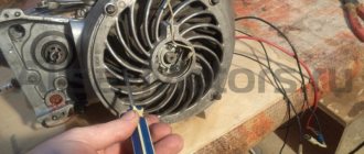
You need to remove the fan grille and the metal ring that secures the fan impeller.
The next step is to secure the modulator shutter with M4*6 mm screws in place of the eccentric.
The next step is to install the rubber washer from the kit. The washer is installed under the metal ring for fixing the fan impeller.
The next step is to install the fan grille in place.
Next, we attach the optical sensor to the fan grille with M4*10 mm screws from the kit.
Center the optical sensor.
Next, we connect the wiring according to the attached diagram from the kit.
For normal operation of the BSZ it is recommended:
Use only a high-voltage wire from a car (since the ends of motorcycle wires have a built-in resistance of 10-15 KOM, which is not suitable for BSZ).
The switch can be used from a VAZ 2108-09-99 car. Check the voltage in the network. It should not exceed 15 Volts, otherwise the switch will fail or the ignition will work unstably.
The ignition coil can be left original, but can be used from VAZ 2108-09-99 (the spark will become more powerful, which will lead to complete combustion of fuel and a decrease in smoke, + 10% thrust).
The capacitor should be removed; it will hinder the operation of the switch.
Setting up the optical sensor.
Adjust the piston 2-3 mm to top dead center. Loosen the sensor mounting screws. Place the sensor along the adjustment cutouts until the LED lights up, which is the moment of spark formation. Fix the sensor in this position with screws. Sparking occurs when the modulator shutter enters the optocoupler.
After setting up the sensor, place a mark on it and on the body with a marker, which will simplify installation and adjustment the next time it is removed.
The last step is to cover the sensor with a plug. The plug and rubber spacer protect the sensor from light, dust and moisture.
The sensor is protected from moisture, but prolonged contact with water is not advisable.
When driving through tall grass, grass and debris may get caught inside the grille, which can impede the sensor's operation.
Periodically check the optocoupler pair and wipe it from dust and dirt with a damp cloth. Do not use aggressive solutions for this.
1) Optical sensor.
2) Modulator curtain.
3) Sensor mounting screw M4*10 - 2 pcs.
4) Screw for fastening the modulator curtain M4*6 - 2 pcs.
The electrical circuit of the Ant scooter is quite simple and does not contain heavy components. It is used for three main tasks:
- Ignition of the air-fuel mixture in the cylinder. Due to this action, the piston moves, transmitting torque to the flywheel.
- Starting a cold and warm engine.
- Supplying current to lighting fixtures and signal signs (turn signals, parking lights, brake lights).
Ant's electrical equipment is a system with one wire, and the second is the body of the moped itself. All equipment has excellent insulation, eliminating the possibility of short circuits and harm to the driver. Maintenance of electronics on a motorcycle consists only of regular cleaning of the terminals. However, to find the problem, you need to keep a tester at hand. He will accurately determine the problem that is preventing the operation of electrical equipment.
Schematic diagram
Here we are talking about a contact ignition system. If the settings are lost, you will have to restore normal operation yourself. But objectively there is nothing fundamentally complicated about this.
In general, the electrical circuit on Ant scooters falls into the simple category. There are no complex knots provided here.
In fact, Ant's electrical circuit consists of:
- battery;
- speedometer;
- lamps for illuminating the speedometer;
- turn signal indicator;
- spark plugs;
- ignition coils;
- capacitor;
- switch for high and low beam together with a horn button;
- front parking lamps;
- low and high beam lamps;
- turn signal switch;
- sound signal;
- turn signal interrupter relay;
- patch panel;
- lamp switch in the dark;
- generator unit status indicator lamp;
- neutral control lamps;
- neutral gear selection sensor;
- couplings;
- dynastarter;
- ignition system breaker;
- ignition switch;
- 8A fuse;
- brake light switch;
- relay-regulator;
- switching block;
- brake lamps;
- rear parking brake lamps.
This is really a minimum set. And it is more than enough for the Ant to fully work and perform its functions.
Knowing the diagram and features of the device that the Ant scooter received, you can yourself, without outside help, correctly set the disabled ignition, without resorting to the help of specialists.
The circuit used on the Ant scooter is needed to perform 3 main tasks:
- Ignite the air-fuel mixture in the cylinders of a carburetor engine. When ignited, the piston is set in motion, which in turn transmits torque to the flywheel.
- Start a cold and warm engine.
- Supply electric current to lighting devices, as well as signal indicators and sound devices.
In fact, all electrical equipment of the Ant scooter includes a single-wire system. The second is the body of the vehicle.
It is worth noting the high quality of factory insulation, which effectively protects the driver and also prevents the possibility of a short circuit.
Maintenance of the electrical part of the scooter comes down to periodically cleaning the contact terminals. But still, having a tester or multimeter will not hurt to determine exactly why the electrical equipment does not work or fails.
Things went wrong
How to set the ignition on a VAZ 2106 yourself
Of course, the engine had to be half charged with spare parts made by no one. I suspect that the counterfeit goods with which I had to tinker for the last two days are being produced in some garage in Rostov-on-Don, or that the local workers are secretly making this nonsense at the factory. In any case, according to my information, traders bring this disgusting stuff from Rostov. The engine to which I have devoted the last two days has already been converted to a magneto. I don’t know why he bought it - I didn’t ask him for it. The old one was in good condition. Well, since I bought it, we’ll install it. It’s none of my business, of course, but I have an extremely negative attitude towards this kind of collective farm tuning.
Electrical circuit diagram of the Ant scooter
Hai! This wiring diagram of the Ant equipment will be useful to those who restore old Soviet scooters. On our website All about motorcycles, such biker mechanics will find many useful images, as well as texts with tips on tuning iron horses, etc.
This resource also provides news from the world of biker sporting events.
The famous domestic scooter has become a rarity these days. Only occasionally is he encountered on the endless roads of his great homeland. You can buy it for relatively little money. On this motorcycle site you can study the technical characteristics of this utility vehicle.
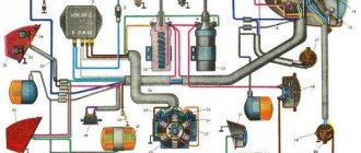
Explanations for the Ant Moto wiring diagram:
1) Direction indicators with bulbs.2) Battery (battery).3) Scooter speedometer.4) Speedometer dial backlight bulb.5) Motorcycle ignition system spark plug.6) Ignition system coil.7) Ignition system capacitor.8) Switching mechanism/ turning off the high beam and the sound signal. 9) Front parking light bulb. 10) Main lighting bulb (low/high beam). 11) Turn signal switch.
12) Sound signal playback device.
13) Scooter turn signal relay. 14) Switch. 15) Night light switch. 16) Generator operation identification indicator light. 17) Neutral transmission identification indicator indicator. 18) Identification mechanism for engaging neutral gear in the gearbox.19) Motorcycle clutch.20) Bike dynastarter.21) Interrupter for the ignition system of a Soviet scooter.22) Ignition system lock.23) Ignition system fuse.24) Stop switch/switch signal.25) Moto Ant relay-regulator.26) Switch block.27) Brake light bulb.
28) Rear marker lamp.
Contactless ignition Ant, Tula (FULL set of BSZ Muravey 2.5)
Topic of the section Homemade electronics, computer programs in the General Questions category; Hello everyone, I have an idea to install a spark ignition on my engine, I don’t have money to buy a specialized ignition, I want to make Forum Rules. Rules Advanced search. Forum General questions Homemade electronics, computer programs Electronic ignition circuit. Dear readers! Our articles talk about typical ways to resolve legal issues, but each case is unique. If you want to find out how to solve your particular problem, please use the online consultant form on the right or call the numbers provided on the website.
How to install a magneto on an Ant scooter. How to set magneto ignition on ant
History of models. Who's online? You are an Anonymous user. You can register by clicking here. Soviet scooters: Forum. Previous topic :: Next topic. Matroskin Interested Registered: Dec 16, Messages: Explain how to do this on your fingers, the instructions say about some kind of meter, etc.
To come back to the beginning. First, you need to write on what engine. Everything written below concerns Tula ones. If I'm not mistaken, the opening of the contacts should begin 2. If the ignition is normal: we hook a 12V light bulb with one end to ground, the other to the terminal of the coil to which the wire from the contacts goes, take an iron rod about 6 mm, about 10 cm long, unscrew the spark plug, stick the rod into hole, lightly resting on the piston, rotate the rotor counterclockwise until TDC, set TDC, put a notch on the rod with a needle file, pull out the rod, and put a second mark at a distance of 2.
Now we turn on the ignition, stick the rod back with the same side, and turn the rotor counterclockwise, when the SECOND risk mark that you made the 2nd time appears, it is at THIS moment that the light bulb that you connected to the coil should light up, if it lights up earlier or later, then loosen the screws and turn the ignition to the correct position. Well, it seems to be something like this on the fingers. Labuh wrote:. Now turn on the ignition, stick the rod back with the same side, and turn the rotor counterclockwise, when the SECOND mark appears, it is at THIS moment that the light bulb that you connected to the coil should light up, if it lights up earlier or later, then loosen the screws and turn the ignition , choosing the correct position.
Damn, how intricate! It’s all true, but in practice it practically doesn’t work! PLAY is inherent in this ignition. I usually adjust it while moving, achieving the best traction. In general, we have known about electronic ignition for a long time. We have written and rewritten a lot about this. Or do you mean a breaker? Matroskin wrote:. Andrey wrote:. Guys, I keep turning and turning the impeller, but the lamp is still on.
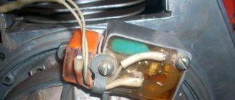
I closed the breaker with a screwdriver and it still lights up. Taxes in order. How should it stand, with the armor wire socket closer to the frame or vice versa? Or from the coil directly to the breaker? Do not swear! A person turns on the ignition for the first time, and even an experienced one sometimes grabs his head. Matroskin, if you take a photo of the ignition unit installed on your scooter, the eccentric, the breaker and its contacts, the wire going to the coil, the coil and its terminals, then it will be more convenient for us to show everything in the pictures.
And so again point by point: 1. Secure the breaker eccentric to the dyno starter housing. Install the fan grille and secure it with 4 M6 screws. The slot for the wire coming from the breaker contacts should face up.
Install the breaker contacts into the recess of the fan grille. Secure them with screws. The contacts should look down and be located to the left of the eccentric.
Connect the wire coming from the contacts to the minus terminal of the ignition coil. Attach the capacitor wiring to the same terminal, and secure the capacitor itself to the fan volute housing. Connect the positive wire coming from the ignition switch to the coil to the “plus” terminal. If there are no markings on the coil terminals, it means it doesn’t care where its plus and minus are. Connect the temporary light bulb with one wire to the negative terminal of the coil, and the other to ground. Turn on the ignition.
Loosen the screws securing the base of the breaker and turning it counterclockwise or clockwise, find the moment when the “temporary” lamp lights up, this is the moment of ignition, the moment of the spark.
If everything works out, carefully secure the base of the breaker and start it. It happens that the lamp is constantly on or does not light up at all. The reason for this may be: a large gap on the breaker contacts, a short circuit of the contacts to ground, misalignment, or the fan grille is not installed correctly.
If for some reason you cannot install the ignition, start reading everything from the beginning. Non-motorized flea market Motorized flea market – Archive What-where-how much Swamp Closed forum Comments on the operation of the site and forum.
How to set the ignition timing on an Ant scooter so that the engine runs and starts well?
In order for any internal combustion engine to start and “work well” (and it is the Internal Combustion Engine installed on your scooter), you need to supply fuel to it and then ignite it at the right moment. Moreover, the engine does not work in only two cases:
- or there is nothing to burn...
- or there is nothing to set on fire...
You are interested in the second case. So:
The work of any internal combustion engine is to convert the reciprocating motion of the piston into the rotational motion of the shaft. This transformation occurs with the help of a crank mechanism (CSM). How this transformation occurs is known from the elementary school “Physics” course.
For “good” operation of the internal combustion engine, all the fuel must burn in the cylinder within a very specific time - while the shaft rotates at a certain angle. Like the picture below:
In order for the fuel to burn at the necessary moments of movement of the piston along the cylinder, it must be ignited in a timely manner. In the Ant engine, the fuel is ignited by a spark in a spark gap called a spark plug. The ignition system, consisting of the following elements, organizes the formation of a spark between the electrodes of the spark plug:
- spark plug;
- ignition coil with capacitor;
- current breaker;
- current source (battery and generator);
- connecting wires.
How the listed elements work and interact with each other can be read in the same “Physics Primer” for elementary school. Here I will only remind you that a spark in the spark plug occurs at the moment the breaker contacts open. It is this moment in time that must be captured when setting the ignition timing. “Physically” this is quite simple to do. When the current source is turned off, we clamp the strip of paper with the contacts of the breaker. Smoothly turning the engine power take-off shaft with one hand, we pull our paper strip with the other. When the contacts release the strip, at that moment the event we need will occur in the spark plug.
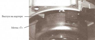
Now you need to organize the “spark supply” at the required moment of piston movement. This process is also not particularly sophisticated. Insert a “match” approximately 250 - 300 mm long into the hole from the inverted spark plug. By rotating the power take-off shaft, we determine the position of the piston at top dead center (TDC) and make a mark on the match. From this mark we set aside 10 mm upward - this will be the ignition point of the fuel, the position of the piston when a spark should appear in the spark plug and the fuel should ignite. By rotating the power take-off shaft, we place the piston at the ignition point. Well, now, by rotating the body of the breaker with a strip of paper clamped by the contacts, we catch the moment when they release the strip.
That's it - the ignition is installed, you can connect a working, charged battery and start the engine. If there is something to set on fire, the engine of your “Ant” should definitely start. More accurately, the ignition is installed with the engine running using a strobe light using special marks on the engine body.
This method of setting ignition timing is good because it does not require power to the ignition system.
That's it - good luck to you and the “ant” on the road...
Ant dino starter operating principle
The dynostarter as a device is as far from complete perfection as our VAZ plant is from the premium segment. But if at least once a season you carry out competent maintenance of the collector unit, switching equipment, and battery, then with all its inherent shortcomings, the dyno starter can last a very, very long time, up to 30,000 km, or even more.
Basic faults
- Mechanical, caused by natural wear, combustion of windings, destruction of contact groups
- Structural, due to design features
- Malfunctions of the relay regulator that lead to dyno starter failure
The most unpleasant malfunctions are related to mechanics: combustion of windings, interturn short circuit, wear or destruction of the commutator. Other mechanical faults such as wear or sticking of brushes, contamination of the commutator, breakage or oxidation of wires and terminals can be eliminated quite easily.
Diagnostics
The first sign that something has burned out, shorted or broken in the dyno starter or relay regulator is when, out of the blue, right in the middle of the road, your battery charge control lamp comes on.
If this happens to you, then the first thing you need to do is inspect the wires going from the dyno starter to the relay regulator, check the fuse, remove the cover from the relay regulator and at least visually determine the integrity of its elements, remove the rotor and see what’s wrong with the brushes and collector and if nothing suspicious is found there, turn to a very competent electrician for help.
You can try to identify the fault yourself, and within the framework of this article it would be possible to describe all the stages of testing, including the author’s developments, but none of you will do this. In the best case, poke it a couple of times with the tester and you’ll give up on this matter, or even end up using a magnet instead of a dynostarter.
The second sure sign that your dyno starter is in perfect order, but it’s just time to service it, is when, at idle and low engine speeds, the charge warning lamp first begins to blink slightly, then begins to burn more steadily and after a while begins to burn at full intensity throughout engine speed range.
In both the first and second cases, without disassembling the dynostarter, little can be learned about its condition, so if there are any complaints about its operation, we roll up our sleeves, prepare the tool and get started.
Disassembly
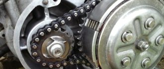
We remove everything that interferes with the removal of the rotor, hold the rotor by the fan with your hand and unscrew the nut
A good owner should have a washer and a lock under the nut. The bad one won’t even have a nut...
Remove the rotor from the crankshaft. The rotor can be removed either with a factory puller or with a homemade one - it makes no difference.
First of all, we inspect the rotor commutator and brushes. The commutator must not show any wear or damage. For example, this collector is just dirty and after we wash it, the dynostarter will start working again.
And some deer broke out the lamellas of this collector. Such a rotor will be difficult to help and easier to throw away. To prevent this from happening to your rotor, select bolts for the coupling for the magnet and the fan of the appropriate length, and do not put everything you have on hand there...
This collector was pulled up by something, the lamellas were shorted together and the dynostarter died. If you find a good turner, he will be able to sharpen the scuffs and the rotor’s performance will be restored.
There are situations when the rotor is dropped or the windings are hit. You understand that damage to the power windings will not improve the reliability of your scooter’s power supply system, so handle such devices very carefully and use pullers, and do not knock them down like tractor drivers with a hammer.
On this rotor, someone smacked the windings with relish.
Cleaning the collector
Take a small screwdriver and clean out the dirt between the slats. The collector must be cleaned very carefully so as not to scratch the lamellas.
After cleaning, blow the collector with compressed air, wash it with clean gasoline and wipe it dry with a rag.
When the gasoline has completely evaporated, take a piece of some lint-free cloth, moisten it a little in gasoline and carefully rub the collector with the maximum possible force until it is perfectly clean.
Checking the rotor windings
We switch the tester to the continuity mode and check the winding contours for breakdown: we place one probe on the rotor body, and with the second we touch all the lamellas in turn. If the tester beeps on any lamella or displays a lot of numbers on the screen, the winding is broken and the rotor should be replaced.
Connection
This vehicle, like all other light motor vehicles, has a two-stroke engine. Firstly, the combustible mixture in the engine cylinder is ignited, due to which the piston moves and then rotational motion is transmitted to the flywheel. I think that the Tula Motorcycle Plant should equip at least some of its vehicles with a modern starter from the SZA motorized stroller and an alternating current generator. The new circuit ensures reliable engine starting and sufficient battery charge.
I think that the Tula Motorcycle Plant should equip at least some of its vehicles with a modern starter from the SZA motorized stroller and an alternating current generator. All equipment has excellent insulation, eliminating the possibility of short circuits and harm to the driver.
For the most part, the Ant motorcycle is designed to transport large loads, so it was not equipped with special lighting parts.
Starting a cold and warm engine. Make a notch at a length of 4.mm. Close the contacts of the breaker when the piston is at TDC.
The electrical equipment of the Ant scooter is securely mounted on the body of the scooter and has good insulation, so the likelihood of a short circuit is negligible.
We recommend reading:. →WIRING DIAGRAM TMZ ➧DISASSEMBLY, PRINCIPLES OF OPERATION
System assembly and installation
The contacts in the breaker, the capacitor, the ignition bobbins and the armor wires, which are part of the previous ignition device, are probably eliminated. The switch should be installed in the glove compartment on the right, and the ignition coil directly under the tank. There are no gaps for fastening on the reel, which means it can be attached using a thick layer of adhesive tape. The standard bolt is also eliminated along with other parts.
In place of the bolt, install a pin of the specified size and put on a washer. Then, the rotor is tightened with a nut located at its end. The hall sensor is attached to the stator by any means. The basic rule when installing it is to set the optimal cross-sectional distance of the modulator and the ratio of the radius and line of symmetry.
When the hall sensor can be secured, we apply the modulator. It should fit into the hole made in the sensor. In most situations, there is a discrepancy between the sizes, so it is necessary to place washers on the stud. If you manage to maintain the required gap, it is recommended to install an engraver and tighten the modulator with a third-party nut.
anthill scooter
I'll give my two cents.
First, decide what the scooter will be used for and how often it will be used. A 2000 year old is probably fine, so leave the working system alone, but put the battery at 12V/17H, go easy and start with the key. Tens of thousands of people must travel to disable a dynastarter.
As for the cam ignition, with all its shortcomings, it seems that the timing is not entirely accurate and so on. It has one big advantage - simplicity. Three details you can see and touch. Moreover, mechanics almost never surprise, which is not the case with electronics.
When problems arise, it is best to address them when they become available. Like any equipment, ants have their problems (with the dynastarter, clutch, carburetor, etc.). However, for many, this method has worked for decades with minimal care.
Well done admin Published March 25, 2011 - 16:51
The generator and starter in the same dynastar bottle remain in place, the switch is removed from the ant. An adapter is made between the shaft and the end of the crankshaft, the front panel is placed on the dynastarter housing, and a magnet is attached to it. Since the magnet will protrude, you will need to make a cutout in the hood. Were there diagrams and pictures in motorcycle magazines for 9? of the year. It was converted into a magnet and into a Voskhod generator. I liked the version with a generator better - in 20 years of operation, I changed the switch once, and that was all the maintenance.
Emil30_30 Published January 28, 2013 - 13:46
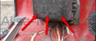
Members, I have a question for you. but in general it is possible to restore the entire enton mechanism, today I looked at the failure genes going to the coil and since I bought it second hand I would like to know if there is a relay that can be used instead of the usual one (pp-121 / 2903.3702) , since it is impossible to find it now, if you tell me I will be grateful.
Emil30_30 Published January 28, 2013 - 19:49
Home // How to install the ignition on a film anthill | | rel = 0; control = 0; showinfo = 0; iv_load_policy = 3;" frameborder =»0″ Fullscreen>
Sleeves on scooters. How to set up a magnet.
Subscribe to the new channel. https://m.youtube.com/channel/UCMds5tPNqtfKfhl-mOmQFTw.
Installing a magnet on an Ant motor, part 2
Installing a magnet on an Ant engine (part 2)
In each case, the reason may be completely different, so you must understand it deeply. Three holes with a diameter of 7 mm are drilled in the fan cover, which are necessary for attaching the magnetic adapter.
Like most Soviet equipment, this cargo scooter is reliable and easy to use, but a little rough around the edges.
Wiring diagram for Ant motorcycle
Electrical connection diagrams are usually quite complex and require special skills in order to understand the wires and the purpose of a particular element. But the Ant motorcycle is quite simple in design, so its electrical circuit is very simple.
For the most part, the Ant motorcycle is designed to transport large loads, so it was not equipped with special lighting parts. But it has the most necessary things, and the connection diagram will help you figure out the breakdown or configure the wiring. For the most part, the circuit may be needed due to a malfunction of the basic elements of movement.
Firstly, when starting a cold or already well-warmed one, problems may arise in the operation of light bulbs or other connecting devices. To solve the problem, a visual inspection may not be enough and you will need an electrical diagram.
Also, most of the “ants” that have been preserved since Soviet times have turn signals, brake lights and other light indicators. If they break down, be sure to have a wiring diagram. The final reason for using the diagram below is to check the flywheel, which receives torque when the piston moves.
Also useful for repairs:
- Glossy suspended ceiling with lighting photo
- Marinade for pumpkin for the winter
- DIY omron tonometer repair