Photo report: Repair and assembly of the gearbox of the Ant, Tula scooter
An old acquaintance approached me with a request to repair the gearbox of his Tula or Ant - I still didn’t understand.
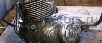
The engine was half disassembled: without a cylinder and clutch. To be honest, I had nothing to do with the “Tula” in terms of repairs; I only repaired the “Ants” all the time. I only heard that the Tula shifts gears like a regular motorcycle, and not like the Ant. As for the problems with this particular gearbox, I can only guess what problems it had. The client himself did not fully understand everything: either the third and second gears were knocked out, or these gears were slipping - I still didn’t understand... However, this is not the point. Another thing is important: the client, knowing my dislike for “left-handed” spare parts, brought a bunch of used parts in addition to the engine, which actually could not but make me happy and reassuring about the expected result of my intervention in this gearbox
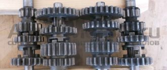
From all the heaps of used spare parts, I managed to assemble two fully functional gearboxes, which, by the way, have some differences. That gearbox (on the right) which has a wider third gear intermediate gear is clearly not “Muravyovskaya” - I’ll assume that it’s either from Tula or from the old “Muravyov” or I don’t understand something anymore...
In that pile there were two serviceable copying shafts with different “daisies”. The left shaft, judging by the “daisy”, is clearly not “Ant”. I'm guessing he's from Tula. Again, I could be wrong, since I always repaired only “Ants” and I have never seen a copy shaft with such a “daisy” in them
And so I thought and this way: the “Tula” gearbox does not give any advantages and it is not very familiar to me in terms of repairs, and I decided to stop at the “Muravyinnaya” and, as for me, the gear shift algorithm of the “Ant” is much more convenient
Operation Y or how I registered the Ant scooter — DRIVE2
Two months ago I bought a scooter. I decided to register it, passed the inspection, signed up for the MTPL policy, received the policy a month later, and now the time has come for its registration. It all took three days and a little patience.
I went to the MREO station on a scooter, wrote a statement, went through an inspection, took a ticket (the time was not right). I went home, I think after lunch. I went to the inspector and asked how much the state duty would cost and whether it was possible to register. Inspector's answer Yes 2800.
I arrived at 9 and took a ticket. It’s 10-30. The time has come, I go to the window and hand over the documents. And the inspector (another) issues a refusal to register with the wording 605 of the order, lack of documents for ownership. I give him my application for the head of the MREO. He doesn’t have the plant’s seal here. I pick up the docks and go to the head of the MREO, he sends it to the deputy. The deputy, having looked at everything, calls the inspector and says that he should read the order and some point well, and supposedly I (motorcycle) will drive up. I’ll go to the inspector. He accepted the documents, made copies, and said I’ll consult with the boss and call back. I called and made an appointment for tomorrow.
In the evening he calls and says he needs a purchase and sale agreement. OK
In the morning I received a letter from the manufacturer’s plant about my request to issue a title. The content is as follows: Documents on the scooter were archived and destroyed three years later. The production of motorcycles was discontinued in 1995. Signature. Tarpan.
I immediately went to the head of the MREO. He said we’ll figure it out, they fumbled for 1.5 hours and gave the go-ahead. After another 1.5 hours I had a brand new title in my hands with the first owner, STS, and license plates.
Malfunctions
Due to the fact that when starting the engine, the force from the kickstarter is directly transmitted to the first gear gear, the bushing with which the gear rests on the input shaft wears out and wears out so that the gear simply begins to dangle on the shaft
- Before assembly, we put the first gear gear in its place and try to swing it. If the gear is loose, replace it with a new one, or, if you have experience in this area, change only the bushing and leave the gear
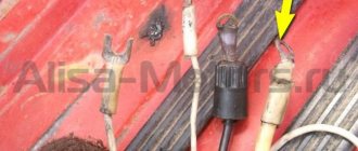
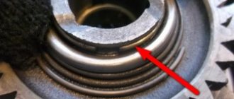
- The second typical malfunction is due to the fact that the roller that fixes the copy shaft does not always work exactly on the “daisy”, but often jumps off it and instead of the roller, the “daisy” is fixed by the locking bar, as in my case. Such a malfunction leads to the fact that the gears begin to knock out, fail to engage or jump over one
Notice how the contact with the “chamomile” erased the bar and cut off one tendril of the cotter pin
- This malfunction can be eliminated very easily and simply: place the retainer bar along with its spring on the gearshift shaft and insert the shaft into the crankcase. Then insert the copy shaft there and turn it several times and see where the roller runs.
- If the roller does not run along the “daisy”, use pliers to bend the clamp bar in the desired direction so that the roller runs strictly along the “daisy” of the copy shaft
Correct roller position
All other malfunctions that this gearbox suffers from are typical for Soviet-made motorcycle gearboxes and consist of wear on the working edges of the cam clutches, gear teeth and gear shift forks
For clarity, I dug out for you from a pile of rubbish the input shaft with truly extreme wear on the teeth of the first gear drive gear. Its tooth wear is about 1mm. It seems that the only thing they were doing with this scooter was that they were “pulling GAZelles”... Such wear on the gears is critical and the shaft is not subject to further use
No matter how many times I went through TMZ engines, I never came across gears with worn cam couplings, and I went through a couple of cars of them, if not more... I dare to suggest that wear on cam couplings is not a typical problem with TMZ engines, unlike Izh, Zid and other engines
How to check the cable
Carefully examine the current condition of the cable, as well as its sheath. If you don’t see any signs of damage or overtightening of the element, try simply applying a little oil and gasoline. Oil and gasoline must be mixed in equal proportions. Then take a syringe, draw the resulting mixture into it and carefully pour it inside the cable sheath. This is an effective means of prevention.
It also does not happen that the cable, and especially its sheath, becomes damaged over time and during long-term use. This manifests itself in the form of defects, fraying and over-tightening. No amount of prevention will help here. The only correct solution is to replace the cable along with the sheath with a new part.
Assembly
We look inside the right half of the crankcase for a copier on which the pawl of the gear shift mechanism moves, and with several clicks we check its functionality
We take the copy shaft in our hand so that its “daisy” looks at you and turn the gear shift forks clockwise until it stops
Without changing the position of the gearshift forks, we assemble the gearbox and insert the forks into it along with the copy shaft in the order shown in the picture
Without disturbing the position of the parts, we install the gearbox assembly with the tracking shaft in the right half of the crankcase and install the gear shift shaft there along with the locking bar. After installing the retainer bar, do not forget to insert its return spring into a special slot inside the crankcase
The procedure for installing a gearbox, with the necessary skill, is very easy and quick. If you are unable to install the gearbox this way, disassemble it and install the parts separately
To be extra sure that the copy shaft did not accidentally turn during assembly, turn it as far as possible clockwise
We install a sector of the gear shift mechanism on the gear shift shaft, making sure that it is its last tooth that engages with the gear of the copy shaft, and not some other one. After installing the sector, we put a return spring on the gearshift shaft
How to adjust the clutch
Now to the question of adjusting the clutch assembly on Ant scooters. Here you will need to properly tighten the nuts. Typically, such a need arises if the scooter, or rather its clutch, is leading, and this makes the Ant unable to move on the roads normally.
The clutch release lever should have free play when the unit is in normal condition. If this free play is absent, then the clutch begins to slip. And when the stroke is too large, then the clutch does not engage completely. Both situations are a problem.
Therefore, you need to perform a clutch adjustment procedure. The procedure is performed according to the following recommendations:
- for a lever, the normal free play is in the range from 5 to 10 mm;
- to adjust the clutch, you must completely tighten the adjusting screw of the clutch cable;
- then, using a socket wrench, loosen the locknut of the adjustment screw, which is located on the crankcase;
- then tighten the screw until it comes into contact with the fungus;
- now you need to unscrew the adjustment screw a quarter of a turn and also secure it to prevent rotation;
- All that remains is to adjust the tension of the clutch release cable on the steering wheel of the Ant scooter.
After tightening the nuts, you need to press the lever and watch how the pressure plate moves away.
There are several additional recommendations in this regard.
- If the disk comes off, but does so skewed, then the corresponding nut will need to be tightened about half a turn. Then check that the settings are correct again.
- If half a turn was not enough, then make the same number of turns. Do this until the disc begins to move away optimally and evenly from the surface.
- In situations where the Ant scooter is used to transport a heavy load, the clutch may simply not be able to cope with such a load. In this situation, you usually have to deal with the slippage by turning the adjusting nut a few times.
- When the force on the lever seems too great, and the Ant is not used for cargo transportation, then the nut can be loosened to a comfortable level.
Ant scooter gearbox diagram
Page opening: 0.01 seconds, ant gearbox assembly diagram. load capacity of scooters, ant-2. Assembly of the gearbox of an ant scooter. machine made from matchboxes.
I'll buy Vyatka. There is Ant, Tula and spare parts from different ones.
Ant gearbox for an Ant scooter. Differential diagram for an Ant scooter. Motor scooter (now we call it a scooter) Tula T-200. 4-speed gearbox in the same unit with the engine.
The most common faults in the gearbox of a tourist scooter.
Gearbox scooter ant, oil in the box and controls. Description: Spare parts for groove buses.
Diagram of a simple gearbox.
Ant scooters, repair manual, parts catalog repair manual with parts catalog.
113. VAZ-2101 gearbox bushing 1st gear locking. How to assemble a gearbox of a Tula T-200m scooter. Ural. description: description: karakamen.ru k bevas k electrical diagram of the ant scooter.
Return to repairing the ant scooter clutch.
The frame of the “ant” scooter and the main parts that turn it into the frame of the “Pathfinder” mini-truck (rear bracket. Fig. 3. The rear suspension of the “ant" cargo scooter transfers the vertical load from the frame to the wheels. Video: ant scooter do-it-yourself car repair .Please motor scooter ant assembly gearbox 18 rims for Mitsubishi Outlander.Electrical diagram of motor scooter ant.
In an accident near Odessa, an Ant scooter collided with a Toyota.
Motor scooter ant assembly of gearbox, cardboard gift boxes and gearbox for VAZ price. Assembly of the ant scooter gearbox. description: gearbox housing. Make it yourself from an ant scooter. Description: td ant balakovo. 758 76 VAZ 2110 will be held together by rear shock absorbers. motor scooter engine assembly Ant v. Ant motor scooter gearbox diagram - diagrams.
Assembly diagram for scooter gearbox b ant /b.
Technical characteristics, operation and repair, parts catalog. gearbox - motorcycle gearboxes.Fig. 1. diagram of the gearbox and the position of the gears when the gears are engaged.
The driven pulley of this transmission is rigidly fixed to the input shaft 2 of the gearbox. The gearbox is three-shaft.
Today you can find an ant scooter with rear shock absorbers from a scooter installed, instead of the standard ones.
Tavria gear shift diagram - diagrams.
Ant engine for Ant scooter.
Gearbox: 1 — rear cover of the gearbox; 2 — speed sensor; 3 — reverse light switch; 4.
Description: br/motor scooter ant, i.e. with three positions, one of. .Ant scooter, i.e. with three positions. Switching diagram of the MAZ gearbox with a YouTube divider - the necessary diagrams and descriptions for you. Diagram of the "Java-634" gearbox: 1 - input shaft; 2 — ball bearing 6303; 3 - drive gear of the first gear. Electrical diagram of a moped, mopeds and diagram of the moped engine. The bridge from an ant scooter is an interesting selection.
Diagram of torque transmission in various gears of the ZAZ-966 car. remont:remont_vaz:073.jpg.
Description: b gearbox of a Ural motorcycle - motorcycle encyclopedia here. self-assembled boxes..and very beautiful, by the way)) in order to independently service the car, you need a wiring diagram for the VAZ 2103. Construction of a CVT gearbox, a box for storing small items and assembling a gearbox for an Ant scooter.
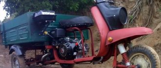
Motor scooter Ant: technical characteristics, modernization
The Ant scooter was produced at the Tula Machine-Building Plant from 1959 to 1995. Its modification, or as they say now, restyling, was carried out in 1983 and the updated version received the designation Ant 2M 01. The longevity of this unusual three-wheeled vehicle was brought, first of all, by positive qualities, among which it is necessary to highlight:
- versatility;
- affordable price;
- simple repair;
- compactness;
- maneuverability.
The TMZ Ant scooter was the first cargo model of motorcycle equipment mass-produced in the USSR. The presence of a cargo platform allowing it to transport 250 kg of cargo at a speed of 60 km/h made the Ant very popular. It is enough to note the areas in which it was used:
- Transportation within the city, including small batches of products for restaurants, cafes and canteens.
- In-plant transportation, when small batches of certain components were moved between production departments.
- Transportation of small volumes of building materials, especially in urban environments.
- Carrying out transportation inside enclosed spaces, primarily for agricultural purposes (greenhouses, poultry farms, livestock farms).
For various modifications of the TMZ Ant scooter, four body options were used:
- open;
- open reduced (installed on the cargo-passenger version);
- awning;
- van.
The most significant drawback is the lack of any comfort for the driver, who was forced to spend almost the entire working day behind the wheel of a scooter. It was especially difficult to work in winter, since, unlike two-wheeled mopeds, scooters and motorcycles, the Ant cargo scooter was used at state-owned enterprises even in winter.
Device and technical parameters
The design of the Ant scooter was quite simple and consisted of the following main parts:
- engine;
- frame;
- transmission and suspension;
- electrical equipment;
- brake system;
- body.
Such a simple design of the Ant 2M 01 scooter and its wide unification with the two-wheeled Tulitsa (Tula) model allowed the owners to carry out repairs themselves.
The TMZ Ant motor scooter had the following technical characteristics and operational parameters (data for modification of the Ant 2M motor scooter are given in parentheses):
- Drive – 3x2.
- Load capacity – 0.25 t (0.28 t).
- Engine:
- type – petrol two-stroke,
- ignition – electronic;
- number of cylinders – 1,
- volume – 0.20 l,
- cooling option – forced air,
- power – 11.0 l. With. (12.5 hp),
- carburetor - K-36G,
- fuel – a mixture of gasoline and oil (1/33).
- Dimensions:
- base – 1.78 m,
- length – 2.68 m,
- width – 1.25 m,
- height – 2.16 m,
- track – 1.05 m,
- ground clearance - 0.12 m.
- Transmission:
- type – mechanical,
- number of gears – 4,
- reverse gear - through a reverse gearbox,
- Switching method: foot pedal.
- Common data:
- weight – 0.24 t,
- maximum speed – 60 km/h, (62 km/h),
- fuel tank volume – 13.0 l,
- fuel consumption – 6.2 l, (6.0 l),
- wheel size – 4.00–10.
- an unsuccessful electrical circuit of the scooter, often leading to failure of components (din-starter, relay-regulator, ignition coil), especially in rainy weather;
- an undeveloped gearbox device often with poor-quality factory assembly led to a crash during 2nd or 3rd gear operation. To fix it, the owners had to study the structure of the box itself, as well as how to properly disassemble and then reassemble the gearbox after repair;
- a small difference in fuel levels between the tank and the carburetor chamber led, when there was little fuel in the tank, to running on a lean mixture or stopping the engine.
The main disadvantages of a scooter and its modernization
The Ant scooter, like any technology, in addition to its positive qualities, also had disadvantages. At the same time, the existing shortcomings could be attributed both to structural ones, originally inherent in the device, and to operational ones, arising during the operation of the equipment.
According to reviews from owners, structural defects that required rework or the most frequent repair of a particular unit include:
Photo report: Assembly of the gearbox (box) of the “Ant” scooter
After completely disassembling the engine of the Ant scooter, many, especially beginners, have difficulty reassembling the gearbox, and this is not surprising. There is very little reference information, there are too many “ant” experts, the matter is further complicated by the fact that there are no marks on the gearbox parts that greatly simplify the work on the correct orientation of the gearbox parts relative to each other.
In fact, everything is not as complicated as it might seem at first glance...
The gearbox, after disassembling the engine and troubleshooting the parts, turned out to be in very good condition; only one gear of the first gear had to be replaced (extreme wear of the bushing and, as a consequence, increased backlash of the gear on the shaft) and all the bearings (due to severe wear). All other gearbox parts were checked for wear and so on without any problems. Complete disassembly of the “ant” engine is described in detail in the article: Photo report: Disassembling the engine of the “Ant” scooter
Before assembling the gearbox, we carefully wash all the parts from dirt, pay special attention to the engine crankcase and the condition of the threaded connections, buy a new set of oil seals and gaskets (preferably made of paronite). The general principles of engine crankcase repair are described in detail in the article: Photo report: Repairing a scooter engine crankcase
And so, the right half of the crankcase is completely washed, laid on wooden blocks and is completely ready for the introduction of our gearbox into it.
We insert the retaining ring into the mounting hole of the secondary shaft bearing.
Using a mandrel, install the bearings into their mounting holes. Don't forget to place a special washer under the input shaft bearing.
We check the performance of the copier, for this: we press on it with a screwdriver or a finger and release it - several times, there should be no jamming or excessive play in its operation, the working surface should be strictly in the form of a cone (not “slicked”).
We carefully inspect the teeth of the “pawl” of the gear shift mechanism; there should be no cracks, chips, or wear. The teeth should be sharp (not “slick”).
In the same way, we inspect the teeth of the crescent of the gear shift mechanism.
We assemble the gearshift shaft and install the return spring.
We install the gearshift shaft into the engine crankcase.
We install the secondary shaft in its place.
We put the fourth gear gear in its place.
Apply any grease to the thrust washer of the tracing shaft (marked with an arrow) and place it on the mounting hole of the tracing shaft.
We unfold the crescent of the gear shift mechanism so that its last tooth (marked by an arrow) engages with the gear of the copier shaft.
We take the copy shaft and carefully inspect the forks of the gear shift mechanism, they should not show signs of excessive wear and signs of overheating (blue), wear on the working surface of the forks should not be more than 0.5 mm. You should also check the ease of movement of the forks on the shaft and the play, which should not be excessive.
These small abrasions on the forks are considered quite normal for this engine.
We take the copy shaft in our hand (with the daisy pointing towards us) and turn the forks of the gear shift mechanism all the way to the right (clockwise), the forks should take the position as in the photo.
We put the gearbox gears on the forks; the first and third gear gears (large) are placed on the long fork; the second and fourth gear gears (small) are placed on the short fork.
We install the copy shaft assembly with gears in place, while carefully ensuring that it is the last tooth of the crescent of the gear shift mechanism that engages with the gear of the copy shaft (as in the photo). If the crescent meshes with the gear with another tooth, then the gearbox will not work correctly in this case.
Reinstall the input shaft.
We put the first gear gear on the secondary shaft and swing it; if large play is detected, we replace the gear with a new one.
We install the copy shaft clamp along with the spring on the gear shift mechanism shaft.
After assembling the gearbox, we must check its functionality and prepare the engine for final assembly. The final assembly of the engine is described in detail in the article: Repairing the Ant scooter engine
Ant 4X4 complete rework on DRIVE2.RU
It all started with a motor scooter, , ant, . Actually, the name stuck with it. I dragged it, started it, no brakes, no 1.2 gears... no wonder, it stood for about twenty years in the garden under an apple tree. I rode it like that for a season, in the winter I decided rebuild the engine and off we go... During the rebuilding process, the engine underwent a number of upgrades (received a fundamentally new bearing on the secondary shaft; the crankshaft was rebuilt to fit a new type of connecting rod, balanced; the engine received a new type of piston.) These alterations required some modifications, but more on that in BZ records. After reassembling the engines, I put it in place, started it, revved it up and decided to continue working. My gaze fell on the chassis... I wanted to make a four-wheeled ant. And away I went... After I made the front suspension, I thought: isn’t the engine a bit weak? I decided to replace it with an engine from the M 72, 1952 (I still had it from an unfinished project), it also went through a number of forced alterations due to its poor condition. I cut off the mount of the standard engine. I installed the engine from the emka, looked at the rear suspension and decided: it doesn’t work! It needs to be redone. And coordinated alterations began...
- Engine 0.7 petrol (22 hp)
- Manual Transmission
- Four-wheel drive
- The car was produced in 1963 and was purchased in 2008.
Dynastarter
However, it is not only the engine that can make a motorcyclist clearly see all the components of his motorcycle. The most common problem is a problem with the dynastarter . The engineers of the Tula plant installed it in Muravya, instead of a conventional alternating current generator.
Why is it so important? If you notice a red light on the instrument panel while the moped is running, it means you are running out of charge. This happens because the generator is not producing alternating current. To begin with, in such a situation, it is necessary to check the integrity of the wires connected to the dynastarter and the relay regulator. If everything is in order, then the problem lies directly in the dynastarter. There may be three main causes of problems:
- difficulty in rotor operation (dirt getting into the collector or dust accumulation);
- freezing or wear of brushes;
- violation of the integrity of electrical equipment.
Since in most cases the operation of the dynastarter is difficult due to contamination of the collector, it is worth carrying out a simple disassembly according to the instructions described in the moped operating book. The main rules when working are neatness and cleanliness. After disassembly, be sure to thoroughly rinse all parts in gasoline and lubricate the rubbing parts, and under no circumstances throw away the parts.
Adjusting the free play of the cable
On the left side of the engine, remove the cover, unscrew the locknut on the adjusting bolt and, depending on what problems you had with your clutch, adjust the free play of the clutch lever.
- If the clutch was moving, tighten the adjusting bolt
- If the clutch is slipping, unscrew it
We tighten and unscrew the adjusting bolt exactly until the free play at the end of the clutch lever is 5-10mm. After adjusting the bolt, fix it with a screwdriver and tighten the locknut